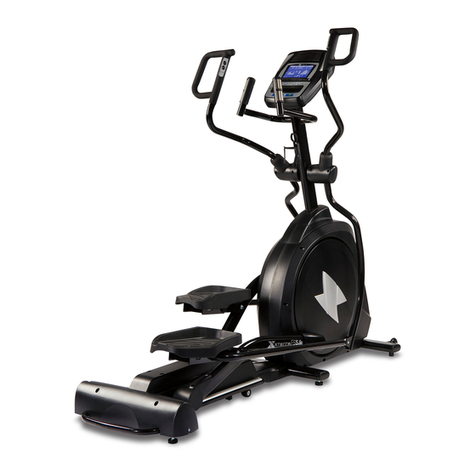
Fuel Fitness XE322 User manual

Service Manual
Elliptical XE322

1
Plastic Parts
Pedal (L) Front Handle Bar Cover (L) Console Assembly
Rear Handle Bar Cover (L) Drink Bottle Holder Console Mast Cover
Side Case (L) Rear Handle Bar Cover (R)
Slide Wheel Cover Front Handle Bar Cover (R)
Rear Stabilizer Cover (B))
Pedal (R) Rear Stabilizer Cover (B)) Round Disk Cover
Rear Stabilizer Cover (A) Connecting Arm Cover (L)
Side Case (R) Pedal Arm Cover (R)
Round Disk Connecting Arm Cover (R)
Transportation Wheel

2
Skeleton
Lower Handle Bar (L) Swing Arm (R) Cross Bar
Connecting Arm (L) Lower Handle Bar (R)
Swing Arm (L) Console Mast
Bushing Housing
Rear Rail Assembly Pedal Arm (L) Main Frame
Pedal Arm (R) Idler Wheel Assembly
Drive Pulley
Connecting Arm (R)
Flywheel

3
Table of Contents
I. Replacing Parts
1 The Console
2 Side Cases
3 Idler Wheel Assembly
4 The Flywheel
5 The Steel Cable
6 The Cross Bar
7 The Belt
8 The Drive Pulley
9 Connecting Arms
10 Pedal Arms and the Bushing Housing
11 Slide Wheels
II. Troubleshooting
1 The Console
2 The Gear Motor
3 Side Cases and the Round Disk
4 The Belt
5 The Flywheel
6 Lower Handle Bars
7 Bushing Housing
8 Pedal Arms, Connecting arms and Slide Wheels
Q & A
1 Noises
2 Slippage
3 Play
4 Smoothness and other problems

4
Model XE322 Work Replacing Parts
The Part 1. The Console Rev.
Procedures:
1. Use Phillips head screw driver to
release four M5x10mm Phillips head
screws, disconnect the computer
cable and hand-pulse cable
to take the
console apart, as shown in figure 1.
2. Reverse above procedure to resume
the console.
2
3
4
1

5
Model XE322 Work Replacing Parts
The Part 2. Side Cases – the right side Rev.
Procedures:
1.
Take the pedal arm apart as shown in
figure 5.
2.
Slap the console mast cover backward
to separate it from side covers, as
shown in figure 6.
3.
Use Phillips head screw driver to
release nine 3.5x12mm self tapping
screws and three 5x16mm tapping
screws which secure the right side
case, as shown in figure 7 & 8.
4.
Reverse above steps to resume the
right side case.
5
6
7
8

6
Model XE322 Work Replacing Parts
The Part 2. Side Cases – the left side Rev.
Procedures:
1. Follow the procedures to take the
right side case apart.
2. Use Phillips head screw driver to
release 4x16mm self tapping screw
and 1/4”x19 flat washer on the
console mast, as shown in figure 1.
3. Release three 5x16mm tapping
screws, as shown in figure 2.
4. Release the nut which secure the DC
cable and pull it out to take apart the
left side case, as shown in figures 3 &
4.
5. Reverse above procedures to resume
the left side case.
1
2
3
4

7
Model XE322 Work Replacing Parts
The Part 3 Idler Wheel Assembly Rev.
Procedures:
1.
Follow the procedures to take apart the
right side case and use 13mm wrench
to loosen M8x7T nut on the J-bolt and
use 13mm wrench to release
M8x20mm carriage bolt, 5/16”
x23x1.5
flat washer and M8x7T nut in order to
take the idler wheel assembly apart, as
shown in figures 1 & 2.
2. Reverse above procedure to resume
the idler wheel assembly.
3. Tighten M8x7T nut on the J-bolt and
use sound wave belt tension gauge to
make sure belt tension is equivalent to
170 +/- 10 Hz.
1
2
3
4

8
Model XE322 Work Replacing Parts
The Part 4 The Flywheel Rev.
Procedures:
1. Follow the procedure 2 to take apart
side cases and procedure 3 to take
apart idler wheel assembly.
2. Plug in and turn on the power. Adjust
the resistance on the console to the
maximum level (XE330=16 while
XE320 and XE420=20), as shown in
figures 1 & 2.
3. Use 15mm wrench to release both
3/8" -UNF26 x 9T nuts which secure
the flywheel on the main frame, as
shown in figure 3.
4. Take the steel cable apart from the
flywheel, as shown in figures 4 & 5.
5. Take apart the flywheel from the
mainframe. Separate the belt from the
flywheel.
2
3
4
1

9
Model XE322 Work Replacing Parts
The Part 4 The Flywheel Rev.
Procedures:
6. To resume the flywheel, return the
belt onto the flywheel notches and
install the flywheel on the mainframe.
7. Tighten the flywheel the both 3/8"
-UNF26 x 9T nuts.
8. Return both the steel cable onto the
flywheel and idler wheel assembly.
9. Turn the drive pulley and check if the
belt runs well. Adjust both 3/8"
-UNF26 x 4T nuts to make sure the
belt locate in the center on the drive
pulley. Make sure the belt is with
proper tension, as shown in figures 6
& 7.
10. Resume all parts.
5
6
7
8

10
Model XE322 Work Replacing Parts
The Part 5 The Steel cable Rev.
Procedures:
1. Follow procedure 4 to take apart
flywheel.
2. Use 10mm wrench release the nut on
the steel cable and take it apart, as
shown in figures 1 & 2.
3. Reverse above steps to resume the
steel cable.
1
2
3
4

11
Model XE322 Work Replacing Parts
The Part 6 The Cross Bar Rev.
Procedures:
1. Follow procedure 2 to take apart side
cases.
2. Tip the round disk cover to take it
apart, as shown in figure 1.
3. Use 12mm wrench to release 5/16”
x3/4” hex head screw and
5/16”x35x1.5 flat washer, which
secure the cross bar, use
Allen wrench
to loosen Socket Head Cap Bolt and
take the cross bar apart, as shown in
figures 2 &3.
4. Return 7×7×25L Woodruff Key onto
the drive pulley axle and resume the
drive pulley, or resume the drive
pulley first and match the Woodruff
Key, then tighten the screws, as
shown in figure 4.
5. Tighten M8x30mm Socket Head Cap
Bolt with 600KGF . CM of torque.
6. Resume all parts.
1
2
3
4

12
Model XE322 Work Replacing Parts
The Part 7 The Belt Rev.
Procedures:
1. Follow the procedures 2, 4 and 6 to
take apart side cases, flywheel and the
cross bar respectively, as shown in
figure 1.
2. Reverse above procedures to resume
parts.
1
2
3
4

13
Model XE322 Work Replacing Parts
The Parts 8 The Drive Pulley Rev.
Procedures:
1. Follow procedures 2, 4, 6 and 7 to
take apart side cases, the flywheel, the
cross bar and the belt in order,
respectively.
2. Take apart the
Woodruff Key and use
C-ring pliers to release Ø 25 C-ring
which secure the drive pulley axle, as
shown in figure 1 & 2.
3. Pull out the drive pulley and the axle
or use the rubber hammer to hit the
axle to take it apart, as shown in
figure 3.
4. To separate the axle from the drive
pulley, use two 11mm wrenches to
release four 1/4” x3/4” hex head
screws together with four 1/4” nuts,
as shown in figure 4.
5. Reverse above procedures to resume
all parts. Be sure to return Ø35x Ø
25.5 x5T plastic washer on the axle.
2
3
4
1

14
Model XE322 Work Replacing Parts
The Parts 9 Connecting Arms Rev.
Procedures:
1. Take apart the connecting arm covers
as shown in figure 1.
2. Use 12mm and 13mm wrenches to
release 5/16” x 1-1/4” hex head
screw, 5/16” x20x1.5T flat washer
and 5/16” x7T nut, which secure the
rod end bearing, as show in figure 2.
3. Use 12mm wrench to release 5/16”
x3/4” hex head screw and 5/16”
x23x1.5T flat washer which secure
the connecting arms and pull out the
pedal axle to separate the connecting
arm from the pedal arm, as shown in
figure 3.
4. Release four M5x10mm Phillips head
screws to further disassemble the
connecting arm, as shown in figure 4.
1
2
3
4

15
Model XE322 Work Replacing Parts
The Parts 9 Connecting Arms Rev.
Procedures:
5. To resume the connecting arm, align
the screw holes on the connecting arm
and the pedal arm and insert the pedal
axle then tighten the hex head screw,
as shown in figure 5 & 6.
6. Secure the connecting arm with the
lower handle bar.
5
6
3
4

16
Model XE322 Work Replacing Parts
The part 10 Pedal Arm and Bushing Housing Rev.
Procedures:
1. Follow procedures 9 to take apart the
connecting arm.
2. Use M6 wrench and 13mm wrench to
release
M8 x 50 Socket Head Cap
Bolt, 5/16” x23x1.5T flat washer and
M8 x 7T nut, which secure the pedal
arm and the bushing housing, to take
the pedal arm apart, as shown in
figure 1.
3. Use 12mm wrench to release 5/16”
x3/4” hex head screw and 5/16”
x23x1.5T flat washer, which secure
the bushing housing to take it apart,
as shown in figures 2 & 3.
4. To resume parts, remember to return
Ø17 wave washer.
1
2
3
4

17
Model XE322 Work Replacing Parts
The Part 11 Slide Wheels Rev.
Procedures:
1. Use Phillips head screw driver to
release two M5x15mm Phillips head
screws and take the slide wheel cover
apart, as shown in figure 1.
2. Use 12,, wrench to release 5/16”
x3/4” hex head screw and 5/16”
x20x1.5T flat washer in order to take
the slide wheel apart, as shown in
figure 2.
3. To resume the slide wheel, first return
the wave washer on the slide wheel
and insert it onto the shaft and tighten
with 5/16” x3/4 hex head screw and
5/16” x20x1.5T flat washer, as shown
in figures 3 & 4.
1
2
3
4

18
Model XE322 Work Troubleshooting
The Part 1 The Console Rec.
Procedures:
1. If the console does not come on,
check with following procedure.
2. Check and make sure that power
adaptor is plug in and the other end is
insert to the unit.
3. Make sure all harnesses are properly
connected including the console and
computer cable, computer cable and
DC cables, which can be done by
disassembling the console, as shown
in figures 1 & 2.
4. If harnesses are properly connected,
check for the damage of harness or
console malfunction.
5.
To test the power adaptor, switch the
multi-meter to DC voltage and take
the voltage with the probe. If there is
no voltage reading, replace the power
adaptor.
2
3
4
1

19
Model XE322 Work Troubleshooting
The Part 2 The Gear Motor Rev.
Procedures:
1. If there is no resistance, Adjust the
resistance with the console to the
maximum level and verify if there are
click sounds which is the sign of
motor running. If click sound is
heard, the steel cable should be fallen
off. Refer to the section of replacing
the steel cable to take it apart, as
shown in figure 1.
2. If no click sound is heard, open both
side cases and check if harnesses are
properly connected. Use multi-meter
to take current between black and red
terminals. If there is reading, the gear
motor is defective, otherwise, the
cable is damaged and will be
replaced, as shown in figure 2.
3. If there is no problem, verify if the
magnets inside the flywheel move
properly. If the magnets is hard to
move, the flywheel will be replaced.
1
2
3
4
Table of contents
Other Fuel Fitness Elliptical Trainer manuals
Popular Elliptical Trainer manuals by other brands

Horizon Fitness
Horizon Fitness e1100GS owner's manual

NordicTrack
NordicTrack NTCCEL16909.0 user manual

Weslo
Weslo Momentum 605 Elliptical Bedienungsanleitung

NordicTrack
NordicTrack E 8.5 Elliptical Manuale d'istruzioni

HMS
HMS H5813 user manual

Christopeit Sport
Christopeit Sport WP1000 Assembly and exercise instructions