5.Preparing for Use
5.Preparing for Use5.Preparing for Use
5.Preparing for Use
5-1.How to install
5-1.How to install5-1.How to install
5-1.How to install
① Install at a position 200 to 250 mm higter than
the location where the screw are supplied and be
careful not to twist or forcibly bend the feed hose.
② Instll the MK-3110V,MK-3159V on the tabel, while being
careful not to twist or excessively bend the screw feed
hose at this time.
5-2.Installing the wiring and piping
5-2.Installing the wiring and piping5-2.Installing the wiring and piping
5-2.Installing the wiring and piping
5-3.Setup prior to installation work
5-3.Setup prior to installation work5-3.Setup prior to installation work
5-3.Setup prior to installation work
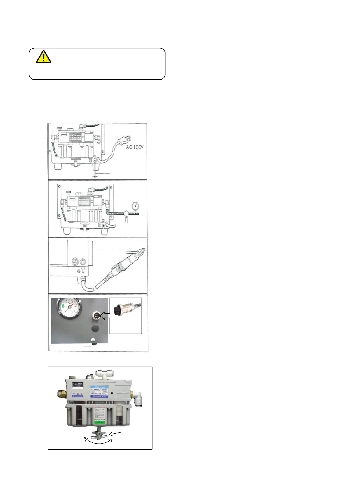
① Setting the screw feed air pressure
① Setting the screw feed air pressure① Setting the screw feed air pressure
① Setting the screw feed air pressure
Open the factory air source (or air compressor)knob
and sue the pressure-relief valve on the air unit to
adjust the pressure as needed while checking the pressure
gauge on the front panel.
Raising the air pressure higher than necessary will damage
the screw feed hose, or the solenoid valve.
Setting the pressure too low ont the other hand will
cause poor screw feed.Normally use a pressure within
0.15 to 0.25 Mpa.
CAUTION
Using an air pressure of 0.35 M a or higher may damage
the solenoid valve, so use a pressure within 0.25 MPa.
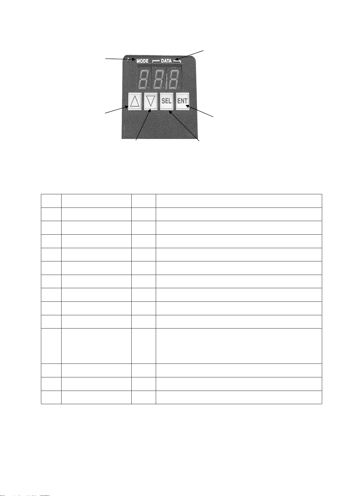
LOW Hig
h
Adjuste
r handle
CAUTI N
Always connect to ground line. Failure to connect
to ground may cause electrical shocks.
1) Connect the ground terminal on the rear panel to
ground by using a ground wire.
2) then connect power supply cord to a power supply.
3) Connect the air hose to the factory air source (or air
compressor). The air hose fitting is the KQ2E08-00.
The source air pressure cannot be adjusted on this
unit, so adjust the factory source air pressure to a
range within 0.4 to 0.5 M a.
4) If using the air screwdriver, connect the air
screwdriver hose to the KQ2E08-00 fitting on the front
panel of the feeder.
5) Connect the screw feed signal plug (from external
section) to the receptacle (3 ) on the front panel of
the feeder.
Ground
Air valve
When useing
Factory air
0.4~0.5M a
みみぞを合わ
せる
I put detches
together
- 9 -