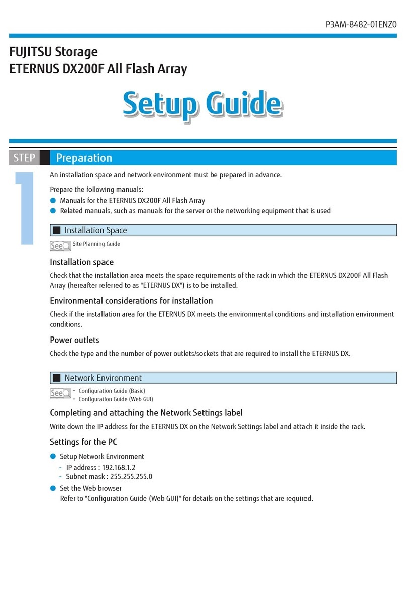
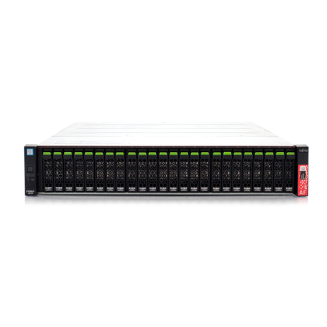
Fujitsu Eternus DX200F User manual

FUJITSU Storage
ETERNUS DX200F All Flash Array
Configuration Guide (Basic)
P3AM-8462-01ENZ0

This page is intentionally left blank.

Preface
Fujitsu would like to thank you for purchasing our FUJITSU Storage ETERNUS DX200F All Flash Array (herein-
after referred to as ETERNUS DX).
The ETERNUS DX is designed to be connected to Fujitsu servers (Fujitsu M10, PRIMEQUEST, or PRIMERGY) or
non-Fujitsu servers.
This manual describes all the procedures that are required to start operation of the ETERNUS DX.
This manual is intended for use of the ETERNUS DX in regions other than Japan.
Please carefully review the information outlined in this manual.
First Edition
May 2014
About This Manual
Organization
This manual is composed of the following eleven chapters:
•"Chapter 1 Component Names" (page 14)
This chapter provides components names of the ETERNUS DX.
•"Chapter 2 Rack Installation" (page 16)
This chapter describes the procedure for installing the ETERNUS DX in a rack.
•"Chapter 3 Checking the Configuration Environment" (page 21)
This chapter describes the environment required for system configuration.
•"Chapter 4 Connecting Cables" (page 31)
This chapter explains how to connect various cables to the ETERNUS DX.
•"Chapter 5 General Settings" (page 34)
This chapter describes the basic settings for the ETERNUS DX.
•"Chapter 6 Monitoring Settings" (page 59)
This chapter describes the settings required to monitor the ETERNUS DX.
•"Chapter 7 Power Control Setup" (page 79)
This chapter describes the settings required for power control of the ETERNUS DX.
•"Chapter 8 SAN Connection Settings" (page 83)
This chapter describes the settings required to use the ETERNUS DX with a SAN connection.
•"Chapter 9 Advanced Copy Settings" (page 115)
This chapter describes the settings required to operate Advanced Copy.
•"Chapter 10 System Status Check" (page 126)
This chapter describes the status check for the ETERNUS DX after system configuration.
•"Chapter 11 Solution Configuration" (page 133)
This chapter describes storage solutions using the ETERNUS DX.
3
FUJITSU Storage ETERNUS DX200F All Flash Array Configuration Guide (Basic)
Copyright 2014 FUJITSU LIMITED
P3AM-8462-01ENZ0
Registered Trademarks and Trademarks
•All SPARC trademarks are used under license from SPARC International, Inc. and are trademarks or regis-
tered trademarks of that company in the United States and other countries.
•UNIX is a registered trademark of The Open Group in the United States and other countries.
•Microsoft, Windows, Windows Server, and Internet Explorer are either registered trademarks or trademarks
of Microsoft Corporation in the United States and/or other countries.
•Oracle and Java are registered trademarks of Oracle and/or its affiliates.
•HP-UX is a trademark of Hewlett-Packard Company in the U.S. and other countries.
•Mozilla, Firefox, and the Mozilla and Firefox logos are trademarks or registered trademarks of the Mozilla
Foundation in the United States and other countries.
•Red Hat is a registered trademark of Red Hat, Inc. in the U.S. and other countries.
•Linux is a registered trademark of Linus Torvalds.
•SUSE is a registered trademark of Novell, Inc. in the United States and other countries.
•IBM, AIX, and Tivoli are trademarks of International Business Machines Corporation, registered in many ju-
risdictions worldwide.
•VMware, VMware logos, Virtual SMP, and vMotion are either registered trademarks or trademarks of
VMware, Inc. in the U.S. and/or other countries.
•The company names, product names and service names mentioned in this document are registered trade-
marks or trademarks of their respective companies.
•Microsoft product screen shot(s) reprinted with permission from Microsoft Corporation.
Naming Conventions
■Product Names
•The following abbreviations are used for Microsoft® Windows Server®.
Product name Abbreviation
Microsoft® Windows Server® 2008 Datacenter
Microsoft® Windows Server® 2008 R2 Datacenter
Windows Server 2008
Microsoft® Windows Server® 2008 Enterprise
Microsoft® Windows Server® 2008 R2 Enterprise
Microsoft® Windows Server® 2008 Standard
Microsoft® Windows Server® 2008 R2 Standard
Microsoft® Windows Server® 2008 for Itanium-Based Systems
Microsoft® Windows Server® 2008 R2 for Itanium-Based Systems
Microsoft® Windows Server® 2008 HPC Edition
Microsoft® Windows Server® 2008 R2 HPC Edition
Microsoft® Windows Server® 2012 Datacenter Windows Server 2012
Microsoft® Windows Server® 2012 Standard
Microsoft® Windows Server® 2012 Essentials
Preface
4
FUJITSU Storage ETERNUS DX200F All Flash Array Configuration Guide (Basic)
Copyright 2014 FUJITSU LIMITED
P3AM-8462-01ENZ0

•The following abbreviations are used for Red Hat Linux.
Product name Abbreviation
Red Hat Enterprise Linux 5 (for x86)
Red Hat Enterprise Linux 5 (for Intel64)
Red Hat Enterprise Linux 5 (for Intel Itanium)
Red Hat Enterprise Linux 5
Red Hat Enterprise Linux 6 (for x86)
Red Hat Enterprise Linux 6 (for Intel64)
Red Hat Enterprise Linux 6
■Symbols Used in This Manual
The following symbol is used throughout this manual:
This indicates information for the user to note when using the ETERNUS DX. Please be
sure to read this information.
This indicates supplementary and reference information.
■Abbreviations Used in This Manual
•"ETERNUS DX200F" or "ETERNUS DX" refers to the FUJITSU Storage ETERNUS DX200F All Flash Array.
•"CA" refers to a host interface module that is used in an ETERNUS DX to connect to a server.
•"Host Bus Adapter (HBA)" refers to the interface module that is normally used by the server to connect to
ETERNUS DX storage systems.
•Trademark symbols such as ™ and ® are omitted in this document.
Preface
5
FUJITSU Storage ETERNUS DX200F All Flash Array Configuration Guide (Basic)
Copyright 2014 FUJITSU LIMITED
P3AM-8462-01ENZ0
Warning Signs
Warning signs are shown throughout this manual in order to prevent injury to the user and/or material dam-
age. These signs are composed of a symbol and a message describing the recommended level of caution.
The following explains the symbol, its level of caution, and its meaning as used in this manual.
This symbol indicates the possibility of serious or fatal injury if the ETERNUS DX is not
used properly.
This symbol indicates the possibility of minor or moderate personal injury, as well as
damage to the ETERNUS DX and/or to other users and their property, if the ETERNUS DX
is not used properly.
This symbol indicates IMPORTANT information for the user to note when using the ETER-
NUS DX.
The following symbols are used to indicate the type of warnings or cautions being described.
Electric Shock
The triangle emphasizes the urgency of the WARNING and CAUTION contents. Inside
the triangle and above it are details concerning the symbol (e.g. Electrical Shock).
No Disassembly
The barred "Do Not..." circle warns against certain actions. The action which must be
avoided is both illustrated inside the barred circle and written above it (e.g. No Disas-
sembly).
Unplug
The black "Must Do..." circle indicates actions that must be taken. The required ac-
tion is both illustrated inside the black disk and written above it (e.g. Unplug).
Preface
6
FUJITSU Storage ETERNUS DX200F All Flash Array Configuration Guide (Basic)
Copyright 2014 FUJITSU LIMITED
P3AM-8462-01ENZ0
How Warnings are Presented in This Manual
A message is written beside the symbol indicating the caution level. This message is marked with a vertical
ribbon in the left margin, to distinguish this warning from ordinary descriptions.
A display example is shown here.
Warning level indicator
Warning type indicator
Warning details
•To avoid damaging the ETERNUS DX, pay attention to the following points
when cleaning the ETERNUS DX:
- Make sure to disconnect the power when cleaning.
- Be careful that no liquid seeps into the ETERNUS DX when using
cleaners, etc.
- Do not use alcohol or other solvents to clean the ETERNUS DX.
Warning layout ribbon
Example warning
CAUTION Do
Preface
7
FUJITSU Storage ETERNUS DX200F All Flash Array Configuration Guide (Basic)
Copyright 2014 FUJITSU LIMITED
P3AM-8462-01ENZ0
Warning Labels and Manufacturer's Labels
Warning labels, manufacturer's labels, and a device ID label are found in the ETERNUS DX, as shown in the
example below.
Never remove these labels from the equipment or allow them to become dirty.
ETERNUS DX200F
Manufacturer’s label
The model name and
the serial number are
listed.
Device ID label
The model name and the serial number
are listed.
Preface
8
FUJITSU Storage ETERNUS DX200F All Flash Array Configuration Guide (Basic)
Copyright 2014 FUJITSU LIMITED
P3AM-8462-01ENZ0
Table of Contents
Chapter 1 Component Names 14
1.1 Front ............................................................................................................................................ 14
1.2 Rear.............................................................................................................................................. 15
Chapter 2 Rack Installation 16
2.1 Controller Enclosure Installation (for Regions Other than EMEA&I).............................................. 18
Chapter 3 Checking the Configuration Environment 21
3.1 System Configuration Example..................................................................................................... 21
3.2 Server Connection Preparation ..................................................................................................... 22
3.2.1 Driver Preparation ..............................................................................................................................................22
3.2.2 Driver Installation ...............................................................................................................................................23
3.2.3 iSCSI Initiator Parameter Settings .......................................................................................................................24
3.3 Preparing the PC Terminal for Setup............................................................................................. 27
3.4 LAN Connection Preparation for Operation Management............................................................. 28
3.4.1 Completing and Attaching the Network Settings Label.......................................................................................28
3.4.2 LAN Related Specifications..................................................................................................................................29
Chapter 4 Connecting Cables 31
4.1 Host Interface Cable Connection................................................................................................... 31
4.2 Power Synchronized Unit Connection ........................................................................................... 32
4.3 Power Cord Connection................................................................................................................. 32
Chapter 5 General Settings 34
5.1 PC Terminal Connection................................................................................................................ 36
5.2 Powering On................................................................................................................................. 37
5.2.1 Switching On and Off the PSU Switch on the Power Supply Unit .........................................................................37
5.2.2 Powering On .......................................................................................................................................................38
5.3 ETERNUS Web GUI Startup ............................................................................................................ 39
5.4 Storage Management (Initial Setup 1)......................................................................................... 40
9
FUJITSU Storage ETERNUS DX200F All Flash Array Configuration Guide (Basic)
Copyright 2014 FUJITSU LIMITED
P3AM-8462-01ENZ0
5.5 LAN Cable Connection (for Operation Management).................................................................... 45
5.6 Firewall Settings........................................................................................................................... 46
5.7 RAID Configuration Settings ......................................................................................................... 48
5.7.1 RAID Group Creation ...........................................................................................................................................49
5.7.2 Operation Volume Creation.................................................................................................................................51
5.7.3 Generation Management Volume (SDV) Creation...............................................................................................53
5.7.4 Temporary Work Volume (SDPV) Creation...........................................................................................................54
5.7.5 Hot Spare Registration........................................................................................................................................56
Chapter 6 Monitoring Settings 59
6.1 Event Notification Setup............................................................................................................... 59
6.2 Various Notification Settings ........................................................................................................ 60
6.2.1 SNMP Trap Setup ................................................................................................................................................60
6.2.2 E-mail Setup .......................................................................................................................................................67
6.2.3 Syslog Setup .......................................................................................................................................................69
6.3 Remote Support Setup.................................................................................................................. 70
6.3.1 Remote Support (by AIS Connect) Setup .............................................................................................................71
6.3.2 Remote Support (by REMCS) Setup .....................................................................................................................72
6.4 Audit Log Setup............................................................................................................................ 74
6.5 Monitoring Server (SNMP Manager) Settings ............................................................................... 75
6.6 Transmission Test Execution......................................................................................................... 76
6.6.1 SNMP Trap Test ...................................................................................................................................................76
6.6.2 Send Test Mail ....................................................................................................................................................77
Chapter 7 Power Control Setup 79
7.1 Setup of the Auto Power Function and/or the Power Resume Function ........................................ 79
7.2 Connection Setup for Power Synchronized Unit ............................................................................ 80
7.3 Wake On LAN Settings.................................................................................................................. 81
Chapter 8 SAN Connection Settings 83
8.1 Connection Settings for the ETERNUS DX...................................................................................... 83
8.1.1 Host Response Settings.......................................................................................................................................83
8.1.2 Host Affinity Settings ..........................................................................................................................................84
8.1.3 CA Reset Group Settings......................................................................................................................................92
Table of Contents
10
FUJITSU Storage ETERNUS DX200F All Flash Array Configuration Guide (Basic)
Copyright 2014 FUJITSU LIMITED
P3AM-8462-01ENZ0
8.2 Server Connection Setup............................................................................................................... 93
8.2.1 iSCSI Initiator Parameter Settings (Connection Information Settings).................................................................93
8.2.2 LUN Recognition Check.....................................................................................................................................102
8.2.3 Disk Partition Settings ......................................................................................................................................104
Chapter 9 Advanced Copy Settings 115
9.1 Advanced Copy Basic Settings .................................................................................................... 115
9.1.1 Copy Priority Settings........................................................................................................................................115
9.1.2 Copy Table Size Settings....................................................................................................................................117
9.1.3 Copy Parameter Settings...................................................................................................................................119
9.2 Performing a Copy (SnapOPC+) .................................................................................................. 120
Chapter 10 System Status Check 126
10.1 Component Status Check.......................................................................................................... 126
10.2 RAID Group Check..................................................................................................................... 127
10.3 Volume Check........................................................................................................................... 128
10.4 Checking Copy Sessions............................................................................................................ 129
10.5 Checking LUNs.......................................................................................................................... 130
10.6 Powering Off ............................................................................................................................ 131
Chapter 11 Solution Configuration 133
11.1 Continuous Business ................................................................................................................ 133
11.2 Performance/Tuning................................................................................................................. 135
11.3 Cloud Platform ......................................................................................................................... 137
11.3.1 Oracle VM Linkage ..........................................................................................................................................137
11.3.2 VMware Linkage .............................................................................................................................................138
11.3.3 Microsoft Linkage ...........................................................................................................................................139
Table of Contents
11
FUJITSU Storage ETERNUS DX200F All Flash Array Configuration Guide (Basic)
Copyright 2014 FUJITSU LIMITED
P3AM-8462-01ENZ0
List of Figures
Figure 1.1 Front View of a Controller Enclosure.........................................................................................................14
Figure 1.2 Rear View of a Controller Enclosure ..........................................................................................................15
Figure 3.1 System Configuration Example.................................................................................................................21
Figure 3.2 Network Setting Label..............................................................................................................................28
Figure 5.1 Example of Differential Backup Settings with SnapOPC+..........................................................................35
Figure 5.2 Example of Creating Operation Volume and Backup Volume ...................................................................36
Figure 5.3 PC Terminal Connection for Initial Setup ..................................................................................................37
Figure 5.4 ON Position (Marked "|") of the PSU Switch on a Power Supply Unit ........................................................37
Figure 5.5 RAID Group Creation.................................................................................................................................49
Figure 5.6 Operation Volume Creation ......................................................................................................................51
Figure 5.7 Generation Management Volume (SDV) Creation ....................................................................................53
Figure 5.8 Temporary Work Volume (SDPV) Creation ................................................................................................54
Figure 8.1 Connection Configuration with Servers.....................................................................................................93
Figure 11.1 Solution — Continuous Business..............................................................................................................133
Figure 11.2 Solution — Performance/Tuning ..............................................................................................................135
Figure 11.3 Solution — Cloud Platform (Oracle VM Linkage)......................................................................................137
Figure 11.4 Solution — Cloud Platform (VMware Linkage).........................................................................................138
Figure 11.5 Solution — Cloud Platform (Microsoft Linkage) .......................................................................................139
12
FUJITSU Storage ETERNUS DX200F All Flash Array Configuration Guide (Basic)
Copyright 2014 FUJITSU LIMITED
P3AM-8462-01ENZ0
List of Tables
Table 3.1 Server (Host) Environment.......................................................................................................................22
Table 3.2 LAN Port Availability.................................................................................................................................29
Table 5.1 RAID Group Creation.................................................................................................................................49
Table 5.2 Operation Volume Creation ......................................................................................................................51
Table 7.1 ETERNUS DX Operation According to the Settings of the Auto Power Function and the Power Resume
Function ..................................................................................................................................................79
13
FUJITSU Storage ETERNUS DX200F All Flash Array Configuration Guide (Basic)
Copyright 2014 FUJITSU LIMITED
P3AM-8462-01ENZ0
Chapter 1
Component Names
This chapter provides component names of the ETERNUS DX.
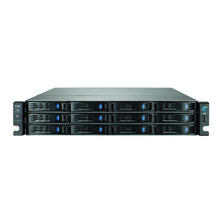
An operation panel and drives are installed in the front of the ETERNUS DX (controller enclosure). Controllers
and power supply units are installed in the rear.
1.1 Front
This section provides the names of the components in the front of a controller enclosure.
Figure 1.1 Front View of a Controller Enclosure
1
3 3
2
1. Operation panel
2. SSD
3. Flange cover
14
FUJITSU Storage ETERNUS DX200F All Flash Array Configuration Guide (Basic)
Copyright 2014 FUJITSU LIMITED
P3AM-8462-01ENZ0
1.2 Rear
This section provides the names of the components in the rear of a controller enclosure.
Figure 1.2 Rear View of a Controller Enclosure
12
34 5 6 7 6 734 5
89
1. Controller (CM#0)
2. Controller (CM#1)
3. PWC port
4. Host interface (CA#0)
5. LAN (RMT) port
6. Host interface (CA#1)
7. LAN (MNT) port
8. Power supply unit (PSU#0)
9. Power supply unit (PSU#1)
Chapter 1 Component Names
1.2 Rear
15
FUJITSU Storage ETERNUS DX200F All Flash Array Configuration Guide (Basic)
Copyright 2014 FUJITSU LIMITED
P3AM-8462-01ENZ0

Chapter 2
Rack Installation
This chapter describes the procedure for installing the ETERNUS DX (controller enclosure) in a rack.
Make sure to check "Safety Precautions" before starting the installation. Also refer to the rack manual.
Do
•Wear a wrist strap or touch a metal part to discharge the human body's natural
static electricity before starting each operation. Failure to discharge static electrici-
ty may cause failure in the ETERNUS DX.
•If components are installed in a way other as described in this section, damage
and/or device failure or electrical shock may occur.
•Do not install the ETERNUS DX in the rack with cables, such as power cords, connec-
ted.
•The ETERNUS DX contains delicate components, and should be handled gently. Do
not drop or knock the ETERNUS DX against the rack when installing it. Also, do not
knock the other devices installed in the rack.
•The center of gravity must be taken into consideration to prevent a rack from top-
pling over. Enclosures should generally be installed from bottom to top to lower
the center of gravity and to ensure the safe use of racks.
Do Not
•Do not uninstall the drives that are installed by default or move them to any other
slot.
Contact your sales representative or maintenance engineer if drives that are instal-
led by default need to be uninstalled or moved to another slot.
16
FUJITSU Storage ETERNUS DX200F All Flash Array Configuration Guide (Basic)
Copyright 2014 FUJITSU LIMITED
P3AM-8462-01ENZ0
•If the storage system is installed at the bottom of a rack, a space for the surplus of cables may not be
available in some racks, preventing the storage system from being pulled out when maintenance work
is required. In this case, secure a space of 1U or more at the bottom when installing the storage system.
•To install an enclosure, power synchronized units, and UPS units in a single rack, mount the devices in
the following order (from bottom to top).
Rack
Controller enclosure
Power synchronized unit
UPS
1
2
3
Installation
order
Chapter 2 Rack Installation
17
FUJITSU Storage ETERNUS DX200F All Flash Array Configuration Guide (Basic)
Copyright 2014 FUJITSU LIMITED
P3AM-8462-01ENZ0
2.1 Controller Enclosure Installation (for Regions Other than
EMEA&I)
This section describes how to install the controller enclosure in a rack.
1Adjust the sizes of the rack rail (for left side) and the rack rail (for right side) to fit the rack.
Loosen the M4 screws to adjust the length of the rack rails to match the distance between the front and
rear rack pillars. Leave the M4 screws slightly unscrewed, as the rack rails must be attached to the rack
before they can be completely tightened.
Loosen the M4 screws to
adjust the length of the
rack rails to match the
distance between the
front and rear rack pillars.
(Rack pillar: front)
(Rack pillar: rear)
Rack rail (right)
An "R" mark is on the inner side.
[Left]
[Right]
Rack rail (left)
An "L" mark is on the
inner side.
2Attach the rack rails to the rack.
Use the two plates to fasten the rack rails to the front rack pillars. Use the four washers to fasten the
rack rails to the rear rack pillars.
Chapter 2 Rack Installation
2.1 Controller Enclosure Installation (for Regions Other than EMEA&I)
18
FUJITSU Storage ETERNUS DX200F All Flash Array Configuration Guide (Basic)
Copyright 2014 FUJITSU LIMITED
P3AM-8462-01ENZ0
Make sure to attach the rack rails to rack pillars so that they fit exactly together without any space
between them.
(Rack pillar: front)
(Rack pillar: rear)
Washer
M5 screw
M5 screw
Washer
M5 screw
Plate
M5 screw
Plate
Rack rail (right)
Rack rail (left)
The M5 screw positions for the rack rails are determined by the controller enclosure base line.
Insert the M5 screws in the 1st and 6th holes on the front rack pillars above the base line and in the
2nd and 5th holes on the rear rack pillars above the base line to fasten the rack rails.
Controller enclosure: front
Controller enclosure: rear
2U
Rack rail
Controller
enclosure base line
Rack rail
Controller
enclosure base line
[Right]
[Left]
6th hole
(M5 screw)
1st hole
(M5 screw)
6th hole
(M5 screw)
1st hole
(M5 screw)
2U
[Right][Left]
5th hole
(M5 screw)
2nd hole
(M5 screw)
5th hole
(M5 screw)
2nd hole
(M5 screw)
3Tighten the M4 screws of the rack rails that were slightly unscrewed in Step 1.
Chapter 2 Rack Installation
2.1 Controller Enclosure Installation (for Regions Other than EMEA&I)
19
FUJITSU Storage ETERNUS DX200F All Flash Array Configuration Guide (Basic)
Copyright 2014 FUJITSU LIMITED
P3AM-8462-01ENZ0
4Install the controller enclosure in the rack.
Do
•When installing or removing the controller enclosure to or from the rack,
make sure that the sides and the bottom of the controller enclosure are held
by two or more people. Failure to do so may cause injury.
5Fasten the controller enclosure in the rack.
Use three M5 screws to fasten it in the rack pillar.
M5 screw
M5 screws
6Attach the flange cover.
Chapter 2 Rack Installation
2.1 Controller Enclosure Installation (for Regions Other than EMEA&I)
20
FUJITSU Storage ETERNUS DX200F All Flash Array Configuration Guide (Basic)
Copyright 2014 FUJITSU LIMITED
P3AM-8462-01ENZ0
Other manuals for Eternus DX200F
2
Table of contents
Other Fujitsu Disk Array System manuals
Popular Disk Array System manuals by other brands

HP
HP 353803-B22 - StorageWorks Modular Smart Array 1000 SAN... installation guide

HP
HP StorageWorks XP128 user guide

HP
HP XP20000/XP24000 Configuration guide

easyRAID
easyRAID Q08QA-2GR2 Hardware manual

easyRAID
easyRAID Q16PS-S3R3 Hardware user manual

VERITAS
VERITAS NetBackup 5330 Hardware Service Procedure

D-Link
D-Link DSN-3200-20 - Xstack 8X1GBE Iscsi San Array 15 Bays... Quick installation guide

EqualLogic
EqualLogic PS3000 Series quick start

easyRAID
easyRAID ERP12R-8FR2 Quick installation guide

Tandberg Data
Tandberg Data RDX QuikStation 4 product manual

easyRAID
easyRAID Q16QS-4GR3 Hardware user manual

Promise
Promise UltraTrak100 TX4 user manual