Functional Devices RIBTWXV-WI Series User manual

Functional Devices, Inc. • p: 800.888.5538 • f: 765.883.7505 • www.functionaldevices.com • [email protected]om
# Relays & Contact Type:
Expected Relay Life:
Operating Temperature:
Operate Time:
Green LED:
Green LED:
Yellow LED:
Pink LED:
Red LED:
Dimensions:
Wires:
Approvals:
Housing Rating:
Gold Flash:
Relay Override Switch:
Current Sensor Range:
Wi:
One (1) SPDT Continuous Duty Coil
10 million cycles minimum mechanical
-30 to 140° F
18mS
Device Status
Wifi Ad-Hoc Status
Wifi Infrastructure Status
Digital Input Status
Relay Status
4.00˝ x 4.00˝ x 1.80˝ with .50˝ NPT Nipple
16˝, 600V Rated
UL Listed, UL916, C-UL
FCC, Wifi Certified ASD Device
UL Accepted for Use in Plenum, NEMA 1 No
DIP Switch Control
0.50 Amp - 20 Amps, in 0.25 Amp increments
IEEE 802.11 b/g/n Compatible
2 Mbps Data Rate
-91 dBm Min. Sensitivity
+102 Bm Max Output Power
Currently Unsecured Connection
(WPA-PSK or WPA-2-PSK Available)
Supports PING and ARP
DSSS Modulation
RIBTWXV-WI Series
Wi IEEE 802.11 Network Enclosed I/O Device: One Discrete Output (20 Amp Relay SPDT +
Override), One Discrete Input (Dry Contact, Class 2); Analog and Digital Current and Relative
Power*Indication; 24 Vac/dc; 120 Vac, 208 Vac, 240 Vac, or 277 Vac Power
Class 2
Dry Contact
Digital Input
2 1
OPEN
DIP Switch
CLOSED
24 Vac
24 Vdc
Common
DIP Switch Relay Control
DIP Switch** Relay State
1 2
0 1 Auto
1 X Override ON
0 0 Override OFF
** 0 = Open ; 1 = Closed
J1 - Not Used
RESET to Factory
Defaults Pushbutton
(Activate with
insulated tool.)
Code
Version
3.1
Power Input:
24 Vac = Terminal Strip
24 Vdc = Terminal Strip (24 Vdc + 25% – 6%)
120 Vac = Wht/Blk Wire
208 Vac, 240 Vac, 277 Vac = Wht/Brn Wire
Neutral or Other Phase = Wht/Yel Wire
Device Settings by Network:
• Power up default relay state
• Host name and location labels
• Relay bound to digital input
• Current threshold for go/no-go status
• Load voltage entry for power conversion
Device Settings:
•Local Override
•Reset to Network Defaults Pushbutton
Specications
Network Compatible Relay / Current Sensor Combos
Notes:
• This device is not intended for revenue
grade power measurement. However, in
addition to Wi load control, this device is
useful for building audits or LEED programs
requiring relative readings to inexpensively
pinpoint high power usage equipment or
to identify energy waste due to equipment
maintenance requirements or
malfunction. *
Power Input Ratings:
125 mA Max @ 24 Vac
88 mA Max @ 24 Vdc
120 mA Max @ 120 Vac (RIBTWXV2401B-WI)
120 mA Max @ 208 Vac (RIBTWXV24208B-WI)
120 mA Max @ 240 Vac (RIBTWXV24240B-WI)
120 mA Max @ 277 Vac (RIBTWXV24277B-WI)
Available TCP/IP Settings:
• IP Address (Static)
• Port Number
•Subnet Mask
•Gateway
• Ad-Hoc mode
• Infrastructure mode
• Scan for wireless networks
Contact Ratings:
20 Amp Resistive @ 277 Vac
20 Amp Ballast @ 120/277 Vac (N/O)
10 Amp Ballast @ 120/277 Vac (N/C)
Not rated for Electronic Ballast
10 Amp Tungsten @ 120 Vac (N/O)
2 HP @ 277 Vac
1 HP @ 120 Vac
RIBTWXV-WI Series Selection Guide
Model# 24 Vac/dc 120 Vac 208 Vac 240 Vac 277 Vac
RIBTWXV2401B-WI • •
RIBTWXV24208B-WI • •
RIBTWXV24240B-WI • •
RIBTWXV24277B-WI • •
•Setup Instructions available on website.
http://www.functionaldevices.com/pdf/bulletins/B1598_393186.pdf
Or scan QR code with your smart phone.
Wi
Made in USA
Meets
“Buy American”
of ARRA 2009
RED LED = Relay Status
PINK LED = Digital Input Status
YELLOW LED = Wi Infrastructure Status
GREEN LED = Wi Ad-Hoc Status GREEN LED =
Device Status LED
Wht/Yel Wht/Blk
or
Wht/Brn
Blu
N/C
Yel
COM
Org
N/O
Power
Sensing

Note: Ad-Hoc Mode is typically used for set-up, but may be used for permanent use.
1. Make note of current computer IP settings and restore settings when nished. If you are unsure of settings, contact your network administrator.
2. Change TCP/IP settings of the computer to connect to the Wi-RIB® as follows:
IP Address: 192.168.100.2 Subnet mask: 255.255.255.224 Default Gateway: 192.168.100.1
3. Connect and apply power to the Wi-RIB® (24Vac or 24Vdc recommended for setup to avoid Line Voltage wiring; all settings will be maintained when power is removed).
The green Device Status LED will ash at a rate of once per second and the green Ad-Hoc Status LED will stay lit while in Ad-Hoc Mode, yellow Infrastructure Status LED will
remain o while in Ad-Hoc Mode (see Device LEDs for other LED indications).
4. View wireless connections on the computer. Look for the network called “WRIBXV” and connect. This establishes a connection between the Wi-RIB® and the computer in
an Ad-Hoc network.
5. In any Internet web browser such as Safari®, Firefox®, or Internet Explorer®, type in the default factory address of 192.168.100.10 and press enter.
Wi RIB®– Getting Started
In the web browser window, you should see the Wi-RIB® main web page. You will be able to control the relay and read status. To change the state of the relay, click the “on”
or “o” button and click “Set Relay”. At the bottom of the page you can see: status of relay, last command, digital Input, load current value, load current threshold setting, load
current above/below threshold status, load voltage setting, and estimated power consumed by load.
Main Page – (Click “Main” link at top of page to return to this page)
Note: Settings can be viewed on Main Page status or in the xml status read outside the web page.
1. Change the RIB default IP address, port number, subnet mask, or gateway if desired – click save after each setting.
Note: The Wi-RIB® ships from the factory with a default IP address of 192.168.100.10, default gateway of 192.168.100.1, and default subnet mask of 255.255.255.224, and
has a unique MAC address for use on the internet or on an internal intranet or network. If at anytime an incorrect address is used or address is forgotten, the Wi-RIB® may be
returned to factory defaults by pressing the RESET pushbutton on the Wi-RIB® until the Device Status LED ashes fast (approx. 5 seconds).
2. Set “Device Name” and click save. Set “Device Location” and click save. (Up to 16 characters.)
3. “Current Threshold” is set to determine at what load amperage the “Load Current Status” changes between “On” and “O”. (Status useful as independent load verication or
logic control in automation systems.)
4. “Load Voltage” is used in calculating the power reading. Determine the load voltage by reading actual voltage or by estimating, 120, 208, 240, or 277 for example. If
the Power Factor is known and is less than 1, it may be calculated into the voltage if desired. For example, a PF of .7 to .8 is common for motors. 120V x .8 = 96, use 96 as
the voltage.
5. “Default Relay Setting” determines the state to which the relay will default upon return from deliberate power-cycle or due to power loss. Make selection for relay to come
on, stay o, or return to last commanded state. After power-up, the relay will follow commanded states if communications are restored.
6. “Digital Input/Relay Binding” allows the relay to be controlled from the Dry-Contact Digital Input if desired. If bound, the relay will follow the state of the Digital Input
(a typical application is a motion-detector controlling the relay that controls room occupancy, status is monitored by Wi). If unbound, the Digital Input may be used as a
general-purpose status input or otherwise (independent of relay).
Setup Page – Network and operational settings (Click “Setup” link at top of page.)
Functional Devices, Inc. • p: 800.888.5538 • f: 765.883.7505 • www.functionaldevices.com • [email protected]

The relay may be controlled over the Wi network by the web page or HTTP commands, by the Digital Input (if binding is set to Bound on the setup page), or manually by the
override DIP switches on the Wi-RIB®. The Digital Input (if binding activated) takes precedence over Wi network commands, the DIP switches take precedence over both the
Digital Input (if binding activated) and the Wi network commands.
Sources of Relay Control and Order of Precedence
HTTP Get commands to control relay and get status bypassing Wi RIB® webpage. Status returned in XML format.
To turn relay on and o:
http://192.168.100.10/index.htm?relay=on
http://192.168.100.10/index.htm?relay=o
To congure relay power up state:
http://192.168.100.10/cong.htm?pwr=on
http://192.168.100.10/cong.htm?pwr=o
http://192.168.100.10/cong.htm?pwr=last
To congure whether relay is bound or unbound to digital input:
http://192.168.100.10/cong.htm?dry=on
http://192.168.100.10/cong.htm?dry=o
To set name, location, digital load status, current threshold and load voltage:
http://192.168.100.10/cong.htm?host=user dened text*
http://192.168.100.10/cong.htm?loc=user dened text*
http://192.168.100.10/cong.htm?threshold=user dened numeric value from 0.5 to 19.75 are valid, values are rounded to the nearest hundreth
http://192.168.100.10/cong.htm?voltage=user dened numeric value 0 or higher. Maximum rating of relay is 277 Vac, but entries over 277 are valid.
It is recommended to enter the actual reading at the load, somewhat lower depending on Power Factor (PF).
* Follow standard URL encoding. Avoid non-alphanumeric characters as they may be interpreted as Escape Codes and may cause errors.
To reset device:
http://192.168.100.10/reset.htm
Wi RIB®– Control and Status by HTTP Commands and XML
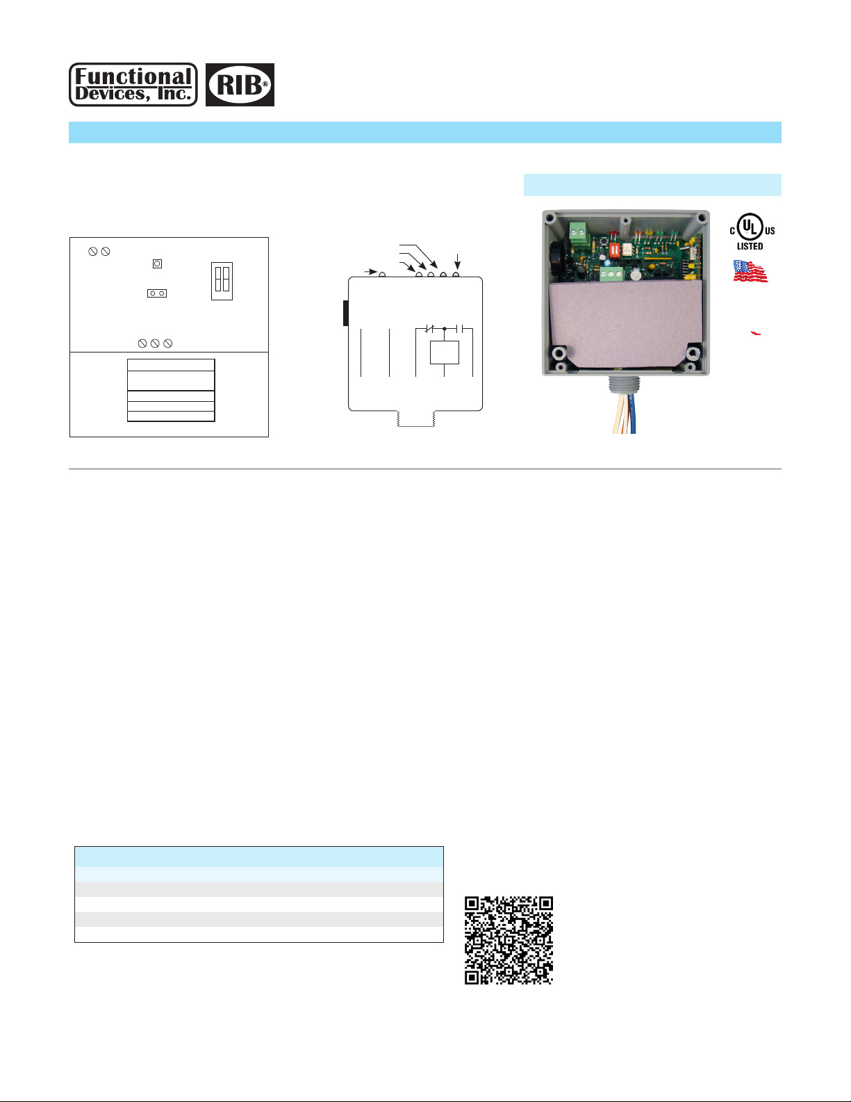
• Green Device Status LED: Flashes at rate of once per second (LED will be on 1/2 second and o 1/2 second). Hesitation in LED may be seen when the Wi-RIB® is answering
HTTP commands.
• Green Ad-Hoc Status LED: On continuously except when HTTP commands are answered at which time the LED will wink o at various rates. LED will be o when in Infra-
structure Mode.
• Yellow Infrastructure Status LED: Flashes at rate of once per second (LED will be on 1/2 second and o 1/2 second) when Wi-RIB® is searching for router either during
original connection, after power cycle of router or Wi-RIB®, or network activity intended to disconnect Wi-RIB®. When HTTP commands are answered the LED will wink o
at various rates. LED will be o when in Ad-Hoc Mode.
• Pink Digital Input Status LED: On if Digital Input is closed, o if open.
• Red Relay Status LED: On if relay is activated (N/O closed, N/C open), o if deactivated (N/O open, N/C closed).
Device LEDs – A description of all LED indications
Note 1: If Wi connection cannot be established to the Wi-RIB®, it may be necessary to manually return to Ad-Hoc Mode. Pressing RESET pushbutton (about 5 seconds) on the
Wi-RIB® will return it to factory default settings, including returning it to Ad-Hoc Mode.
Note 2: You may scan for the desired router if in range, or enter the name and security type of the router – the Wi-RIB® will retain the router information if power is removed
from the Wi-RIB® and will nd the router once power is restored to the Wi-RIB® if the router is in range.
1. To scan for routers in range, click “Scan For Wireless Networks” to nd search list of Wi routers of desired infrastructure network and select router.
2. To enter the name and security type of the router, click “Other Network...”. The green Ad-Hoc Status LED will extinguish and the yellow Infrastructure Status LED will begin
ashing at a rate of once per second until the Wi-RIB® establishes connection to router and then stay lit (see Device LEDs for other LED indications).
The Wi-RIB® will be entered into the infrastructure network on the router. You must now go back to view wireless networks on the computer to connect to the same network
to nd the Wi-RIB®.
Wi Page – To enter the Wi-RIB® into Infrastructure Mode or to return to Ad-Hoc Mode. (Click “Wi” link on top of page)
Functional Devices, Inc. • p: 800.888.5538 • f: 765.883.7505 • www.functionaldevices.com • [email protected]

Other relay states: OFF, OVERRIDDEN ON, ON, BOUND ON, BOUND OFF
Other network command: ON
Other digital in state: OPEN
Load current in 0.25 Amp resolution
User dened threshold for generating digital load status
Other digital load status: ON
User dened load voltage from 0 Vac to 300 Vac
Relative load power
Other default power on states: ON, LASTSTATE
Other binding state: BOUND
User dened label
User dened label
Factory rmware version
<relayState>OVERRIDDEN OFF</relayState>
<lastCommand>OFF</lastCommand>
<digitalInputState>CLOSED</digitalInputState>
<loadCurrent>0.00 Amps</loadCurrent>
<loadCurrentThreshold>1.00 Amps</loadCurrentThreshold>
<loadCurrentState>OFF</loadCurrentState>
<loadVoltage>120.00 Vac</loadVoltage>
<loadPower>0.00 Watts (VA)</loadPower>
<powerOnState>OFF</powerOnState>
<bindingState>UNBOUND</bindingState>
<deviceHostName>Device Name</deviceHostName>
<deviceLocation>Device Location</deviceLocation>
<deviceVersion>v3.0.9 WRIBXV</deviceVersion>
<bss>
<valid>0</valid>
<name>0</name>
<privacy>0</privacy>
<wlan>0</wlan>
<strength>0</strength>
</bss>
<scan>0</scan>
<ver>4615</ver>
<count>0</count>
<ssid>WRIB24XV</ssid>
</response>
Router information
}
Relay is commanded by webpage of device or by HTTP command. Local overrides are done manually by DIP switches and take precedence over webpage, HTTP commands,
or Digital Input if Binding is enabled. Digital Input may be used for general purpose inputs and may be bound to relay to allow direct control of the relay with Digital Input.
Use Default Relay Setting to determine power on state of relay after power cycle; On, O, or Last Commanded State.
For proper power reading, set voltage to which load will be applied.
For ON/OFF “Digital” Load Status, set Load Current Threshold – Load Current Status will indicate if load is ON (above threshold) or OFF (below threshold).
This equipment has been tested and found to comply with the limits for a Class B digital device, pursuant to part 15 of the FCC Rules. These limits are designed to provide
reasonable protection against harmful interference in a residential installation. This equipment generates, uses and can radiate radio frequency energy, and if not installed
and used in accordance with the instructions, may cause harmful interference to radio communications. However, there is no guarantee that interference will not occur in
a particular installation. If this equipment does cause harmful interference to radio or television reception, which can be determined by turning the equipment o and on,
the user is encouraged to try to correct the interference by one or more of the following measures:
• Reorient or relocate the receiving antenna.
• Increase the separation between the equipment and receiver.
• Connect the equipment into an outlet on a circuit dierent from that to which the receiver is connected.
• Consult the dealer or an experienced radio/TV technician for help.
To read status information:
http://192.168.100.10/status.xml
Response will be in the following format:
<?xml version=”1.0” encoding=”utf-8”?>
<response>
Functional Devices, Inc. • p: 800.888.5538 • f: 765.883.7505 • www.functionaldevices.com • [email protected]
071717
This manual suits for next models
4
Table of contents
Other Functional Devices Lighting Equipment manuals