- 2 - ft634aTRC-eng (06.02.2014)
Kompetent für Elektroniksysteme
- 3 - ft634aTRC-eng (06.02.2014)
Kompetent für Elektroniksysteme
Contents
Technical Data 2
General Features 3
Channel Remote Switching 3
Transmitter control 4
Functions of the LEDs 4
Examples 4
Jumper 6
Block diagram FT634a (C, CL, TRC) 7
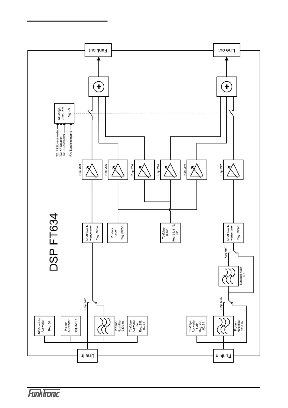
Block diagram DSP 8
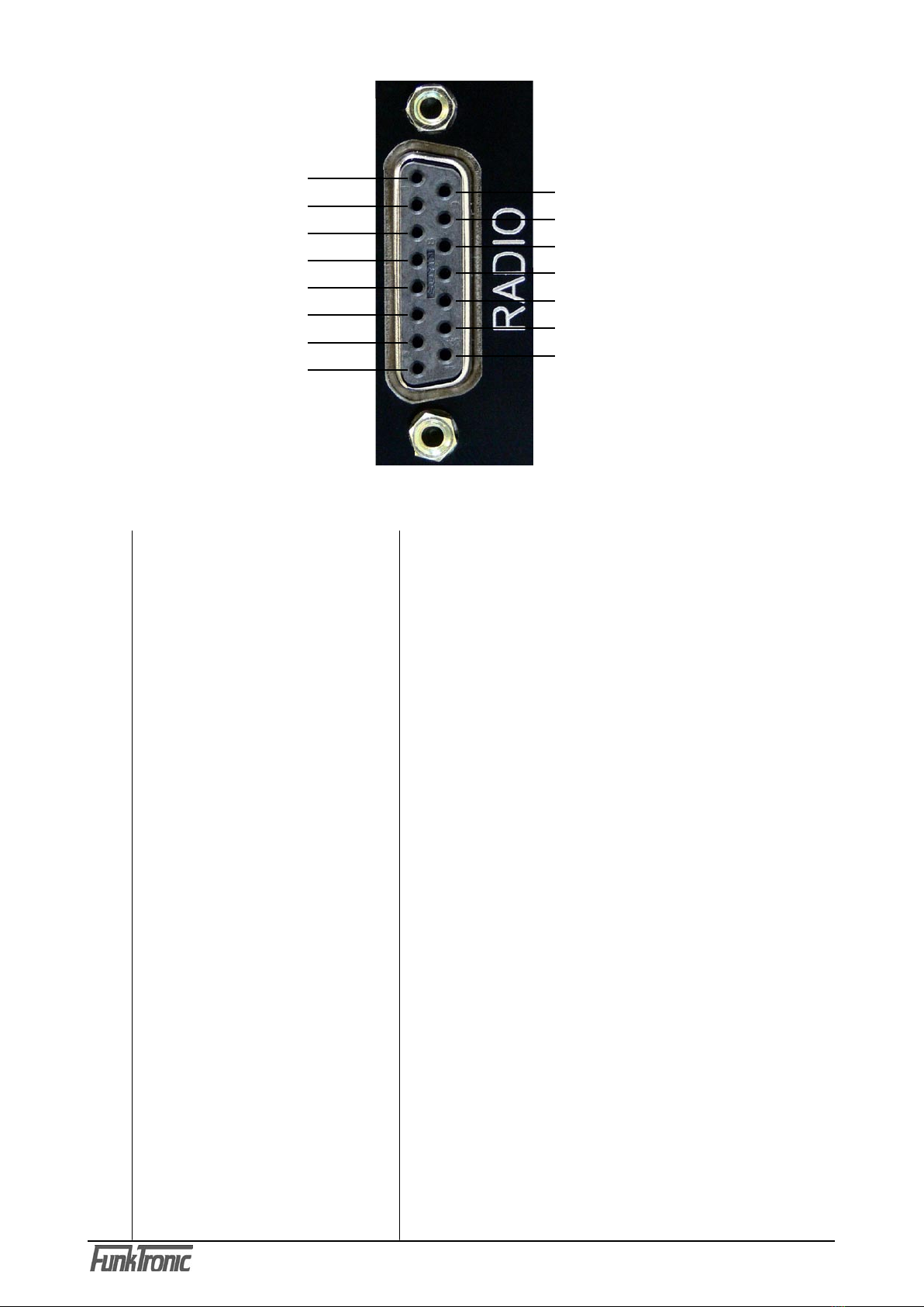
Pinout 9
RS232-connecting cable 11
Service program/Adjustment 11
Programming 13
Tone table 17
General Safety Instructions 18
Terms and abbreviations 19
Page
Technical Data
Voltage of operation +12V DC +/-30%
Current demand ca. 100 mA
Fuse 1 A, self-resetting
Weight ca. 525 g
Dimensions W x H x D 104 x 44 x 175 mm
Frequency of pilot tone ex factory setting: 3300 Hz
Pilot tone decoder +/- 0,8 % (+/- 26 Hz)
Response time < 20 ms
Release time < 40 ms
min. pilot tone level at measuring (monitor.)point 75 mV
Notchfilter pilot tone suppression > 50 dB
2- resp. 4-wire
Input level 2-wire -10 dBm nominally, 250 mV
Adjustment range 2-wire -41 dBm to -1 dBm, 7 mV to 700 mV
Input level 4-wire -9 dBm nominally, 275 mV
Adjustment range 4-wire -40 dBm to +1 dBm, 8 mV to 850 mV
Input impedance 2-wire Zr or 600 Ohm, 4-wire 600 Ohm
Output level 2-wire -10 dBm, 250 mV (or: -19 dBm, 190 mV)
Pilot tone 2-wire -12 dBm, 200 mV
Output level 4-wire -14 dBm, 150 mV (or: -5 dBm, 450 mV)
Pilot tone 4-wire -16 dBm, 125 mV
Output impedance 2-wire Zr or 600 Ohm
Output impedance 4-wire 600 Ohm
Interface radio device resp. desk top control
Input level + 3 dBm nominally, 1100 mV
Adjustment range - 24 to + 6 dBm, 50 mV to 1550 mV
Input impedance 600 Ohm
Output level - 17 dBm ex factory setting, 100 mV
Adjustment range - 30 to + 8 dBm, 25 mV to 2000 mV
Output impedance 600 Ohm