Before you get started:
• Make sure all optical ends
are clean to avoid poor in-
sertion loss readings and
prevent contamination of
the optical ports on the test
units.
• Annual calibration is
recommended.
CAUTION:
Never look directly into the
output ports of the light
source or the ends of a fiber
optic connector. he light may
not always be visible, but can
still cause damage to the eye.
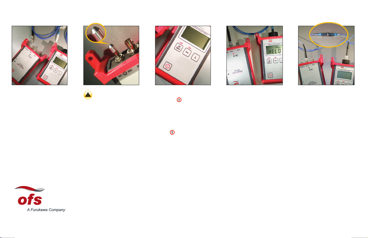
• urn on LIGHT SOURCE by
pulling up on the TOGGLE
SWITCH and moving it to
the left or the right, select-
ing appropriate wavelength.
NOTE:
o turn off light source, pull
up on toggle switch and move
to center position.
• Insert ST®CONNECTOR
end of LAUNCH JUMPER
into appropriate wavelength
port on Light Source.
• Insert other connector end of
Launch Jumper into Adapter
Cap on Power Meter.
• Zero the Power Meter by
pressing and holding down
the Ref button until HELD
and 0.0 dB is displayed.
NOTE:
It is recommended to re-zero
the Power Meter at least every
30 minutes.
• Disconnect connector end
of Launch Jumper from
adapter cap on Power
Meter and insert into
SPLICE BUSHING.
• Insert one connector end of
the DEVICE UNDER TEST
(DUT) into the Splice Bush-
ing.
• Insert the other connector
end of the DU into the
Adapter Cap on the Power
Meter.
• he number on the Power
Meter display represents the
insertion loss due to the
connector at the Splice
Bushing plus the attenuation
through the length of cable.
• urn on POWER METER by
pressing button.
NOTE:
o disable the 5-minute,
automatic-shutdown battery
saver feature, hold down the
button until Pis displayed.
• On the Power Meter press
the dB/dBm button until dB
is displayed.
• On Power Meter press “λ"
button until appropriate
wavelength is displayed.
• Install appropriate
ADAPTER CAP onto Power
Meter.
• Allow 2 minutes for test set
to stabilize.
echnical Support 888.438.9936 | www.ofsoptics.com
Test Kit Quick Start Guide (Procedure illustrates insertion loss by single-ended test method. efer to booklet for loss by substitution method.)
Before you get started:
• Make sure all optical ends
are clean to avoid poor in-
sertion loss readings and
prevent contamination of
the optical ports on the test
units.
• Annual calibration is
recommended.
CAUTION:
Never look directly into the
output ports of the light
source or the ends of a fiber
optic connector. he light may
not always be visible, but can
still cause damage to the eye.
• urn on LIGHT SOURCE by
pulling up on the TOGGLE
SWITCH and moving it to
the left or the right, select-
ing appropriate wavelength.
NOTE:
o turn off light source, pull
up on toggle switch and move
to center position.
• Insert ST®CONNECTOR
end of LAUNCH JUMPER
into appropriate wavelength
port on Light Source.
• Insert other connector end of
Launch Jumper into Adapter
Cap on Power Meter.
• Zero the Power Meter by
pressing and holding down
the Ref button until HELD
and 0.0 dB is displayed.
NOTE:
It is recommended to re-zero
the Power Meter at least every
30 minutes.
• Disconnect connector end
of Launch Jumper from
adapter cap on Power
Meter and insert into
SPLICE BUSHING.
• Insert one connector end of
the DEVICE UNDER TEST
(DUT) into the Splice Bush-
ing.
• Insert the other connector
end of the DU into the
Adapter Cap on the Power
Meter.
• he number on the Power
Meter display represents the
insertion loss due to the
connector at the Splice
Bushing plus the attenuation
through the length of cable.
• urn on POWER METER by
pressing button.
NOTE:
o disable the 5-minute,
automatic-shutdown battery
saver feature, hold down the
button until Pis displayed.
• On the Power Meter press
the dB/dBm button until dB
is displayed.
• On Power Meter press “λ"
button until appropriate
wavelength is displayed.
• Install appropriate
ADAPTER CAP onto Power
Meter.
• Allow 2 minutes for test set
to stabilize.
echnical Support 888.438.9936 | www.ofsoptics.com
Test Kit Quick Start Guide (Procedure illustrates insertion loss by single-ended test method. efer to booklet for loss by substitution method.)
Inse tion-Loss-Quick-Sta t-Guide_Layout 1 9/18/15 3:14 PM Page 1


