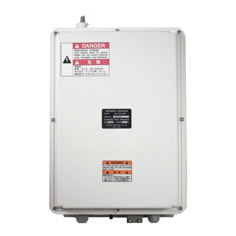
Furuno FV-110 User manual

KU-BAND ANTENNA
FV-110
OPERATOR'S MANUAL
www.furuno.com
Model

The paper used in this manual
is elemental chlorine free.
・FURUNO Authorized Distributor/Dealer
9 52 Ashihara cho,
Nishinomiya, 662 8580, JAPAN
A
:
SEP
2015
.
Printed in Japan
All rights reserved.
B
:
FEB
.
21, 2017
Pub. No.
OME-50990-B
(
YOTA
)
FV-110
0 0 0 1 9 1 0 1 1 1 1

KU-BAND ANTENNA FV-110
Quick guide
Introduction
This quick guide aims at experienced service personnel who have installed the FV-110 system and
connected power. It lists the minimum configuration tasks you have to make before the system. can be
used on-air on a satellite.
Prerequisites
1. Connect a PC to the front LAN connector or the LAN3 connector at the rear of the Antenna Control
Unit.
2. Open an Internet Browser and type the default IP address of the FV-110: http://192.168.0.1 to access
the web interface.
Configuration tasks (minimum)
You find a flow chart for the calibration procedure on page 5-13.
i
Configuration task What to do and where to find more information
Heading input Configure the heading input to External under SETTINGS >
Navigation. For more information see Table 5-1 on page 5-4.
Connect the ship’s heading (RS-422, NMEA0183) to the NMEA 0183
multi-connector. Pin 8 Ship Ground/Shield (connect only one end), Pin 9
Line B +, and Pin 10 Line A-. For more information see NMEA 0183
connector on page 3-3.
Azimuth calibration Make an azimuth calibration under SERVICE > Calibration to ensure
that the FV-110 can point and receive satellite signal. For more
information see Azimuth calibration on page 5-7.
TX cable calibration Make a Tx cable calibration under SERVICE > Calibration to ensure
that Tx power is calibrated at all frequencies. For more information see
Cable calibration on page 5-11.
See Appendix E or http://www.lyngsat.com for DVB-S transponder
information.
Modem connection Connect cables between the modem and the ACU. For more information
see VMU settings on page C-1.
Modem profile Configure the modem profile under SETTINGS > Modem profiles. For
more information see Modem profiles on page 5-22.
Network settings Configure the network settings under SETTINGS > Network if the
modem communicates with IP to the ACU. For more information see To
configure the LAN network on page 5-29.
Satellite profile Configure the satellite profile under SETTINGS > Satellite profiles and
then activate the satellite profile and wait for the system to acquire the
satellite and start tracking. For more information see Satellite profiles on
page 5-24.

Important notice
General
• This manual has been authored with simplified grammar, to meet the needs of international users.
• The operator of this equipment must read and follow the descriptions in this manual. Wrong
operation or maintenance can cancel the warranty or cause injury.
• Do not copy any part of this manual without written permission from FURUNO.
• If this manual is lost or worn, contact your dealer about replacement.
• The contents of this manual and equipment specifications can change without notice.
• The example screens (or illustrations) shown in this manual can be different from the screens you
see on your display. The screens you see depend on your system configuration and equipment
settings.
• Save this manual for future reference.
• Any modification of the equipment (including software) by persons not authorized by FURUNO
will cancel the warranty.
• The following concern acts as our importer in Europe, as defined in DECISION No 768/2008/EC.
- Name: FURUNO EUROPE B.V.
- Address: Ridderhaven 19B, 2984 BT Ridderkerk, The Netherlands
• All brand and product names are trademarks, registered trademarks or service marks of their
respective holders.
How to discard this product
Discard this product according to local regulations for the disposal of industrial waste. For disposal in
the USA, see the homepage of the Electronics Industries Alliance (http://www.eiae.org/) for the correct
method of disposal.
How to discard a used battery
Some FURUNO products have a battery(ies). To see if your product has a battery, see the chapter on
Maintenance. Follow the instructions below if a battery is used. Tape the + and - terminals of battery
before disposal to prevent fire, heat generation caused by short circuit.
In the European Union
The crossed-out trash can symbol indicates that all types of batteries
must not be discarded in standard trash, or at a trash site. Take the used
batteries to a battery collection site according to your national legislation
and the Batteries Directive 2006/66/EU.
In the USA
The Mobius loop symbol (three chasing arrows) indicates that Ni-Cd and
lead-acid rechargeable batteries must be recycled. Take the used
batteries to a battery collection site according to local laws.
In the other countries
There are no international standards for the battery recycle symbol. The number of symbols can
increase when the other countries make their own recycle symbols in the future.
ii
Cd
Ni-Cd Pb

iii
Safety instructions
Read these safety instructions before you operate the equipment.
WARNING
WARNING
Do not open the equipment.
The equipment uses high
voltage that can cause electri-
cal shock. Refer any repair
work to a qualified technician.
If water leaks into the equip-
ment or something is
dropped into the equipment,
immediately turn off the
power at the switchboard.
Fire or electrical shock can
result.
If the equipment is giving off
smoke or fire, immediately
turn off the power at the
switchboard.
Fire or electrical shock can
result.
Indicates a condition that can cause death or
serious injury if not avoided.
Indicates a condition that can cause minor or
moderate injury if not avoided.
WARNING
WARNING
If you feel the equipment is
acting abnormally or giving
off strange noises, immedi-
ately turn off the power at the
switchboard and contact a
FURUNO service technician.
Do not disassemble or modify
the equipment.
Fire, electrical shock or serious
injury can result.
Make sure no rain or water
splash leaks into the equip-
ment.
Fire or electrical shock can
result if water leaks into the
equipment.
Do not operate the equipment
in an explosive environment.
Fire or electrical shock can
result.
WARNING
CAUTION
Warning, Caution Prohibitive Action Mandatory Action

iv
WARNING WARNING
Distance
50W/m
2
30 m
Do not place liquid-filled
containers on or near the
equipment.
Fire or electrical shock can
result if a liquid spills into the
equipment.
Do not operate the equipment
with wet hands.
Electrical shock can result.
Use the proper fuse.
Use of the wrong fuse can
cause fire or electrical shock.
Turn off the power at the
mains switchboard before
beginning the installation.
Post a sign near the switch to
indicate it should not be
turned on while the equip-
ment is being installed.
Fire, electrical shock or serious
injury can result if the power is
left on or is applied while the
equipment is being installed.
Ensure the unit is properly
grounded.
Improper grounding can cause
electrical shock or interference
from/with other devices.
Use equipment with a suit-
able voltage rating for ship’s
mains.
Rated voltage is directed at
each unit, and out of range
voltage may cause damage to
the equipment.
Do not approach the FV-110
antenna unit when it is trans-
mitting.
The radome emits radio waves
that can be harmful to the human
body, particularly the eyes.
RF power density on
antenna aperture
100W/m
2
10W/m
2
Observe the compass safety
distances shown in the table
to prevent interference to a
magnetic compass.
CAUTIOCAUTION
Antenna Unit
Antenna
Control Unit
1.00 m
0.30 m
Unit Standard
Do not manually turn the
polarisation unit of the
antenna.
The antenna can be damaged.
VSAT restrictions
There are restrictions in use of the
frequency band 13.75 to 14 GHz in
the following countries:
Belgium, Hungary, Latvia, Malta,
Slovakia
Connect the VSAT modem provider
for local setups.
Steering
1.70 m
0.30 m

v
Table of Contents
Foreword................................................................................................................................xi
System configuration............................................................................................................xii
Equipment list......................................................................................................................xiii
Chapter 1 Introduction
1.1 FV-110 system ....................................................................................... 1-1
1.1.1 Above Deck Unit (ADU) ...................................................................... 1-2
1.1.2 Antenna Control Unit (ACU) ............................................................... 1-5
1.1.3 VSAT Modem Unit (VMU) ................................................................. 1-7
1.1.4 Satellite type approvals ......................................................................... 1-7
1.1.5 Service activation ................................................................................. 1-7
1.2 Part numbers and options .................................................................... 1-8
1.2.1 Applicable FURUNO model and part numbers ................................... 1-8
1.2.2 Options for FV-110 .............................................................................. 1-8
Chapter 2 Installation
2.1 Unpacking .............................................................................................. 2-1
2.1.1 What’s in the box .................................................................................. 2-1
2.1.2 Initial inspection ................................................................................... 2-2
2.1.3 Tools needed ......................................................................................... 2-2
2.1.4 Transport of the antenna ....................................................................... 2-2
2.2 Site preparation .................................................................................... 2-3
2.2.1 General site considerations ................................................................... 2-3
2.2.2 Obstructions (ADU shadowing) ........................................................... 2-4
2.2.3 Blocking zones – azimuth and elevation .............................................. 2-5
2.2.4 Safe access to the ADU: Radiation hazard ........................................... 2-6
2.2.5 Ship motion and offset from the ship’s motion centre ......................... 2-7
2.2.6 ADU mast design: Foundation and height ........................................... 2-8
2.2.7 Interference ......................................................................................... 2-13
2.2.8 Other precautions ................................................................................ 2-17
2.3 Installation of the ADU ...................................................................... 2-18
2.3.1 To install the ADU ............................................................................. 2-19
2.3.2 To open and remove the service hatch ............................................... 2-23
2.3.3 To ground the ADU ............................................................................ 2-24
2.3.4 Alternative ADU cable ....................................................................... 2-25

Table of Contents
vi
2.4 Installation of the ACU .......................................................................2-26
2.4.1 To install the ACU ..............................................................................2-26
2.4.2 To ground the ACU ............................................................................2-27
2.5 Installation of the VMU ......................................................................2-27
2.5.1 General mounting considerations — VMU ........................................2-27
2.6 To install the dual-antenna mode (optional) ....................................2-28
Chapter 3 Interfaces
3.1 Interfaces of the FV-110 ACU .............................................................3-1
3.1.1 LEDs, display and keypad ....................................................................3-1
3.1.2 ACU connector panel — overview .......................................................3-1
3.1.3 ADU connector .....................................................................................3-2
3.1.4 Rx/Tx connectors for VMU .............................................................3-2
3.1.5 NMEA 0183 connector .........................................................................3-3
3.1.6 RS-232 and RS-422 connectors ............................................................3-4
3.1.7 LAN1, LAN2, LAN3 and LAN4 connectors .......................................3-5
3.2 Interfaces of the VMU ..........................................................................3-5
Chapter 4 Connecting power
4.1 Power up ................................................................................................4-1
4.1.1 Procedure ..............................................................................................4-1
4.1.2 Initialisation steps in daily use ..............................................................4-2
4.1.3 FV-110 operational ...............................................................................4-2
Chapter 5 Configuration
5.1 Introduction to the built-in web interface ..........................................5-1
5.1.1 Overview ...............................................................................................5-1
5.1.2 Connecting to the web interface ...........................................................5-1
5.2 Calibration .............................................................................................5-3
5.2.1 Heading mode and position mode ........................................................5-3
5.2.2 Azimuth calibration ..............................................................................5-7
5.2.3 To set up a service profile for calibration .............................................5-9
5.2.4 Cable calibration .................................................................................5-11
5.2.5 Operation in gyro-free mode ...............................................................5-11
5.2.6 Flow chart for calibration (user controlled).........................................5-13
5.2.7 To make a line up procedure ...............................................................5-14
5.2.8 Fixed TX gain principle ......................................................................5-15

Table of Contents
vii
5.3 Configuration with the web interface ............................................... 5-16
5.3.1 Overview and dashboard .................................................................... 5-16
5.3.2 Modem profiles and satellite profiles ................................................. 5-22
5.3.3 To set up blocking zones (RX and TX) .............................................. 5-27
5.3.4 To configure the LAN network .......................................................... 5-29
5.3.5 E-mail setup ........................................................................................ 5-31
5.3.6 Reports, syslog and SNMP traps ........................................................ 5-32
5.3.7 Dual antenna mode (optional) ............................................................ 5-36
5.3.8 Upload of new software ...................................................................... 5-40
5.3.9 Administration .................................................................................... 5-40
5.4 Keypad and menus of the ACU ......................................................... 5-46
5.4.1 ACU display and keypad .................................................................... 5-46
5.4.2 Navigating the menus ......................................................................... 5-47
5.4.3 The menu tree ..................................................................................... 5-48
5.4.4 Adjusting brightness of the display .................................................... 5-51
5.4.5 Power cycle of the ACU and ADU .................................................... 5-52
5.5 SNMP support ..................................................................................... 5-53
Chapter 6 Installation check
6.1 Installation check list: Antenna ........................................................... 6-1
6.2 Installation check list: ACU, connectors and wiring ......................... 6-3
6.3 Installation check list: Functional test in harbor ............................... 6-5
Chapter 7 Service
7.1 Getting support: Helpdesk ................................................................... 7-1
7.1.1 Help desk and diagnostic report ........................................................... 7-1
7.2 Software update .................................................................................... 7-4
7.2.1 Hardware and software requirements ................................................... 7-4
7.2.2 Software update (ADU and ACU) ........................................................ 7-4
7.2.3 To verify the software update ............................................................... 7-6
7.3 Status signalling with LEDs and status messages .............................. 7-7
7.3.1 LEDs of the ADU modules .................................................................. 7-7
7.3.2 LEDs in the ACU ................................................................................. 7-8
7.4 Removal and replacement of the ACU ............................................... 7-8
7.5 Removal and replacement of ADU modules ...................................... 7-9
7.6 Troubleshooting .................................................................................. 7-12
7.6.1 Overview ............................................................................................ 7-12
7.6.2 Event list for troubleshooting ............................................................. 7-12
7.6.3 Diagnostics report for troubleshooting ............................................... 7-12
7.7 Returning units for repair ................................................................. 7-12

Table of Contents
viii
Appendix A Data sheets
A.1 VSAT LNB Data Sheet (physical LNB) .............................................A-1
A.1.1 VSAT LNB user installation and configuration information ..............A-2
A.2 VSAT 8 W BUC Data Sheet (Extended) ..........................................A-3
Appendix B VMU cables
B.1 Modem Cable COMTECH Serial & RSSI TT7016A ....................... B-2
B.2 Modem Cable iNFINITI iDirect VSAT modem ................................ B-3
Appendix C VMU settings
C.1 Performance optimization for blockage ............................................. C-1
C.1.1 Performance of VSAT systems encountering blockage,
configured with multiple satellites. ...................................................... C-1
C.2 OpenAMIP setup for iDirect iNFINITI & Evolution ....................... C-3
C.2.1 Protocol and interfaces ......................................................................... C-3
C.2.2 Sample options file .............................................................................. C-6
C.2.3 Configuration example (OpenAMIP) .................................................. C-9
C.2.4 Troubleshooting ................................................................................. C-10
C.3 Serial setup for iDirect iNFINITI & Evolution ............................... C-13
C.3.1 Protocol and interfaces ....................................................................... C-13
C.3.2 Console port settings .......................................................................... C-13
C.3.3 Configuration example (Serial) ......................................................... C-15
C.4 COMTECH 570L and ROSS box ..................................................... C-17
C.4.1 Protocols and interfaces ..................................................................... C-17
C.4.2 Configuration example (COMTECH 570L and ROSS) .................... C-18
C.5 COMTECH 570L ............................................................................... C-19
C.5.1 Protocol and interfaces ....................................................................... C-19
C.5.2 Configuration example (COMTECH 570L) ...................................... C-21
C.6 STM SatLink 2900 VSAT modem .................................................... C-22
C.6.1 Interfaces and VSAT modem configuration ...................................... C-22
C.6.2 ACU configuration ............................................................................ C-24
C.6.3 Configuration example (STM Satlink 2900) ..................................... C-25
C.7 Gilat SkyEdge II VSAT modem ....................................................... C-26
C.7.1 Interfaces and VSAT modem configuration ...................................... C-26
C.7.2 ACU configuration ............................................................................ C-27
C.7.3 Configuration example (Gilat SkyEdge II) ........................................ C-28

Table of Contents
ix
C.8 Inmarsat G5 modem .......................................................................... C-29
C.8.1 Interfaces and VSAT modem configuration ...................................... C-29
C.8.2 Connecting a Inmarsat G5 modem .................................................... C-29
C.8.3 Inmarsat G5 Driver ............................................................................ C-29
C.8.4 ACU configuration ............................................................................ C-30
C.8.5 Configuration example (Inmarsat G5) ............................................... C-31
C.8.6 LAN setup requirements for G5 system ............................................ C-31
C.9 Linkway S2 modem ........................................................................... C-32
C.9.1 Protocols and interfaces ..................................................................... C-32
C.9.2 ACU configuration ............................................................................ C-34
C.9.3 Configuration example (Linkway S2) ............................................... C-35
Appendix D Command line interface
D.1 Introduction ......................................................................................... D-1
D.1.1 Telnet connection ................................................................................ D-1
D.1.2 Help ..................................................................................................... D-2
D.1.3 Conventions ......................................................................................... D-2
D.2 Supported commands ......................................................................... D-3
D.2.1 config ................................................................................................... D-3
D.2.2 demo .................................................................................................... D-3
D.2.3 dual_antenna ........................................................................................ D-4
D.2.4 exit ....................................................................................................... D-4
D.2.5 help ...................................................................................................... D-4
D.2.6 modem ................................................................................................. D-5
D.2.7 satellite ................................................................................................. D-5
D.2.8 status .................................................................................................... D-8
D.2.9 system .................................................................................................. D-9
D.2.10 track ..................................................................................................... D-9
D.2.11 zone .................................................................................................... D-10
Appendix E DVB-S satellites.......................................................................................E-1
Appendix F Grounding and RF protection
F.1 Why is grounding required? ................................................................ F-1
F.1.1 Reasons for grounding ..........................................................................F-1
F.1.2 Safety ....................................................................................................F-1
F.1.3 ESD Protection .....................................................................................F-1
F.2 Grounding Recommendations ............................................................. F-2
F.2.1 To ground the ACU .............................................................................. F-2
F.2.2 To ground the ADU .............................................................................. F-2
F.3 Alternative grounding for steel hulls ..................................................F-3
F.3.1 To ground the ACU ................................................................................F-3
F.3.2 To ground the ADU ................................................................................F-4

Table of Contents
x
F.4 Alternative grounding for aluminum hulls .........................................F-5
F.4.1 To ground the ACU ..............................................................................F-5
F.4.2 To ground the ADU ..............................................................................F-5
F.5 Alternative grounding for fibre glass hulls .........................................F-6
F.5.1 To ground the ACU ..............................................................................F-6
F.5.2 To ground the ADU ..............................................................................F-6
F.6 Separate ground cable ...........................................................................F-7
F.6.1 Ground cable - construction ..................................................................F-7
F.6.2 Ground cable - connection ....................................................................F-8
F.6.3 Isolation of the ADU from the mounting base ....................................F-8
F.7 Jumper cable for grounding ...............................................................F-10
F.8 RF interference.....................................................................................F-11
F.8.1 Recommendations ...............................................................................F-11
Appendix G System messages
G.1 Event messages – overview ..................................................................G-1
G.2 List of ADU events ............................................................................... G-2
G.3 List of ACU events ............................................................................... G-8
Appendix H Approvals
H.1 Overview ............................................................................................... H-1
H.2 OEM declaration .................................................................................. H-2
H.3 CE (R&TTE) ........................................................................................H-3
H.4 Eutelsat S.A – ESV Summary Sheet ..................................................H-4
H.5 Russian Maritime Register of Shipping .............................................H-5
H.6 ANATEL Certificado de Homologação .............................................H-8
Specifications.....................................................................................................................SP-1
Packing lists.......................................................................................................................PL-1
Outline drawings..............................................................................................................OD-1
Interconnection diagrams ................................................................................................ID-1
Index...............................................................................................................................Index-1

Foreword
A word to the owner of the FV-110
Congratulations on your choice of the FURUNO FV-110. We are confident you will see why the
FURUNO name has become synonymous with quality and reliability.
Since 1948, FURUNO Electric Company has enjoyed an enviable reputation for innovative and
dependable marine electronics equipment. This dedication to excellence is furthered by our extensive
global network of agents and dealers.
Your equipment is designed and constructed to meet the rigorous demands of the marine environment.
However, no machine can perform its intended function unless properly installed and maintained.
Please carefully read and follow the operation and maintenance procedures set forth in this manual.
We would appreciate feedback from you, the end-user, about where we are achieving our purposes.
Thank you for considering and purchasing FURUNO equipment.
Features
The main features of the FV-110 are as shown below.
• Single 50 Ohm coax cable for the ADU
• Support of several VSAT modems
• Gyro-free operation
• Dual antenna mode
• SNMP support
• Remote or local simultaneous software update of ADU and ACU via PC and Internet browser
• Global RF configuration
• Full remote control and troubleshooting with built-in test equipment (BITE)
• ACU with 4 x LAN, NMEA 0183, NMEA 2000, RS-232 and RS-422
• All interfaces at the ACU, no additional units required
• AC powered.
• No scheduled maintenance
Software version
This manual is intended for FV-110 with software version 1.57.
Software information
This product includes software to be licensed under the GNU General Public License (GPL),GNU
Lesser General Public License (LGPL), BSD, Apache, MIT and others.The program(s) is/are free
software(s), and you can copy it and/or redistribute it and/or modify it under the terms of the GPL or
LGPL as published by the Free Software Foundation. Please access to the following URL if you need
source codes.
https://www.furuno.co.jp/contact/cnt_oss.html
xi

xii
System configuration
The figure below shows an example system configuration.
: Standard supply
: Optional or local supply
Antenna Unit 407009B-FUR-01
Antenna Control Unit
407016C-F19
Satellite Router
iDirectX5
Switching HUB
SRW2008
VoIP Switch
AFG200/400/800
AC Adapter
AC Adapter
AC Adapter
UPS
E11A102B001UJ/
E11A102B002UJ
100-240V AC,
1ø, 50-60Hz
Analog Telephone
Network Equipment
Gyrocompass
19” Rack Console
Equipment category
Unit Category
Antenna
Other units
Exposed to the weather
Protected from the weather

xiii
Equipment list
Standard supply
Name Model Code No. Qty Remarks
Antenna Unit (ADU:
Above Deck Unit)
407009B-FUR-01 - 1 Installation materials
included (See PL-1.)
Antenna Control Unit
(ACU)
407016C-F19 - 1 Installation materials
included (See PL-2.)
Installation Materials CP16-04200 000-015-931 Select
one
30 m 8D-FB-CV cable,
single connector
CP16-04120 000-015-865 40 m 8D-FB-CV cable,
single connector
CP16-04210 000-015-932 50 m 8D-FB-CV cable,
single connector
CP16-04220 000-029-109 60 m 8D-FB-CV cable,
single connector
CP16-06100 000-029-111 Select
one
For 100 ACV (See PL-3.)
CP16-06110 000-029-197 For 200 ACV (See PL-4.)

xiv
Optional supply
Name Model Code No. Remarks
UPS E11A102B001UJ - For 100/110/115/120
VAC
E11A102B002UJ - For 200/220/230/240
VAC
Dual Antenna Mode Kit 407090-010 001-423-880
Jumper Cable 407090A-925 001-423-890

1-1
Chapter 1
Introduction 1
This chapter is organised in the following sections:
•FV-110 system
•Part numbers and options
1.1 FV-110 system
The FV-110 is a unique stabilized maritime VSAT antenna system operating in the Ku-
band (10.7 to 14.5 GHz). It provides bi-directional IP data connections both on regional
satellite beams and quasi-global Ku-band satellite networks. The system only requires a
single 50 Ohm cable to provide the Above Deck Unit with both DC power, data and
control information. The radome does not have to be removed neither before nor after the
installation. To protect the Above Deck Unit the built-in DC motors act as brakes during
transport and when the Above Deck Unit is not powered. The ADU system can be
accessed remotely and in-depth performance analysis can be done using the built-in web
interface.
The FV-110 system consists of the following units:
• Above Deck Unit (ADU)
• Antenna Control Unit (ACU)
The following figure shows the FV-110 system.
Figure 1-1: Above Deck Unit and Antenna Control Unit (ACU)
Above Deck Unit (ADU)
Antenna Control Unit (ACU)

FV-110 system
1-2
1.1.1 Above Deck Unit (ADU)
The FV-110 ADU is a 103 cm VSAT stabilised tracking antenna, consisting of a
suspended antenna with a standard global RF configuration. The ADU’s weight is
126,5 kg. It is stabilized by heavy duty vibration dampers in 3-axis (plus skew) and can be
used in environments with elevations of -25° to + 125°. The ADU is powered by the ACU
and protected by a radome.
Figure 1-2: Above Deck Unit (ADU)

FV-110 system
1-3
Modules in the FV-110 ADU
1. GNSS module.
2. VSAT Interface Module (VIM3).
3. Pedestal Control Module (PCM2).
4. Service switch.
5. Single Motor Driver Module for cross elevation (SMD (used “DDM” in log)).
6. Cross elevation motor and encoder.
7. Zero Reference Module (x4) (ZRM) (not visible on photo). (3 on this figure)
8. Single Motor Driver Module for elevation (on the bottom) (SMD (used “DDM” in
log)).
9. Elevation motor and encoder (not visible).
10.Polarisation Motor Module (PMM).
Figure 1-3: FV-110: Above Deck Unit modules 1/2

FV-110 system
1-4
11.Polarisation motor.
12.Polarisation encoder.
13.Block Up Converter (BUC).
14.Low Noise Block downconverter (x2), (LNB).
15.Ortho Mode Transducer (OMT) (not visible on photo).
16.Inertial Sensor Module (ISM).
17.Elevation locking pin to lock the antenna dish in a fixed position.
In switch-off position the Single Motor Driver modules (SMD (used “DDM” in log))
and the BUC are turned off for safe conditions during service and repair. The switch
must be in on position for normal ADU operation.
18.Single Motor Driver Module for Azimuth (SDM (used “DDM” in log)).
19.Azimuth motor.
20.Azimuth encoder.
21.Rotary joint.
22.Feed horn.
Figure 1-4: FV-110: Above Deck Unit modules 2/2
Table of contents
Other Furuno Antenna manuals