Furuno GP-90 User manual

GPS NAVIGATOR
GP-90

The paper used in this manual
is elemental chlorine free.
FURUNO Authorized Distributor/DealerFURUNO Authorized Distributor/Dealer
9-52 Ashihara-cho,9-52 Ashihara-cho,
Nishinomi
y
a 662-8580, JAPANNishinomi
y
a 662-8580, JAPAN
Tele
p
hone :Tele
p
hone : 0798-65-21110798-65-2111
FaxFax 0798-65-42000798-65-4200
::
FIRST EDITION :FIRST EDITION :AUG.AUG. 20032003
Printed in JapanPrinted in Japan
A
ll ri
g
hts reserved.
A
ll ri
g
hts reserved.
F3F3 :: NOV.NOV. 22, 200522, 2005
Pub. No.Pub. No. OME-44270OME-44270
*
00014746415
*
*
00014746415
*
*
00014746415
*
*
00014746415
*
(( HIMAHIMA )) GP-90GP-90 * 0 0 0 1 4 7 4 6 4 1 5 ** 0 0 0 1 4 7 4 6 4 1 5 *
*
OME
44270
F
30
*
*
OME
44270
F
30
*
*
OME
44270
F
30
*
*
OME
44270
F
30
*
* O M E 4 4 2 7 0 F 3 0 ** O M E 4 4 2 7 0 F 3 0 *

i
SAFETY INSTRUCTIONS
CAUTION
Do not place liquid-filled containers on
the top of the equipment.
Fire or electrical shock can result if a
liquid spills into the equipmtnt.
Do not place heater neat the equipment.
Heat can melt the power cord, which can
result in fire or electrical shock.
Do not operate the unit with wet
hands.
Electrical shock can result.
Use the correct fuse.
Use of the wrong fuse can cause fire or
equipment damage.
No single navigation aid (including this
unit) should ever be relied upon as the
exclusive means for navigating your
vessel.
The navigator is responsible for checking
all aids available to confirm his position.
Electronic aids are intended to assist, not
replace, the navigator.
Use of an autopilot with this unit, to
provide automatic steering to
destination, does not eliminate the
need to maintain a watch.
Always maintains a vigilant watch to
prevent collision or grounding.
Do not open the cover of the
equipment.
This equipment uses high
voltage electricity which can
shock, burn or cause death.
Only qualified person-
nel should work inside the
equipment.
WARNING
Do not dissasemble or modify the
equipment.
Fire, electrical shock or serious injury
can result.
Immediately turn off the power at the
ship’s mains switchboard if water or
foreign object falls into the equipment
or the equipment is emitting smoke or
fire.
Continued use of the equipment can
cause fire, electrical shock or serious
injury.
WARNING
WARNING
To avoid electrical shock, do not
remove cover. No user-serviceable
parts inside. - -
- - - - - - - - - - - - - - - - - - - - - - - - - - - - -
- - - - - - - - - - - - - - - - - - - - - - - - - - - - -
- - - - - - - - - - - - - - - - - - - - - - - - - - - - -
WARNING Label attached
Name: Warning Label (1)
Type: 86-003-1011-1
Code No.: 100-136-231

ii
TABLE OF
CONTENTS
FOREWORD............................................ iii
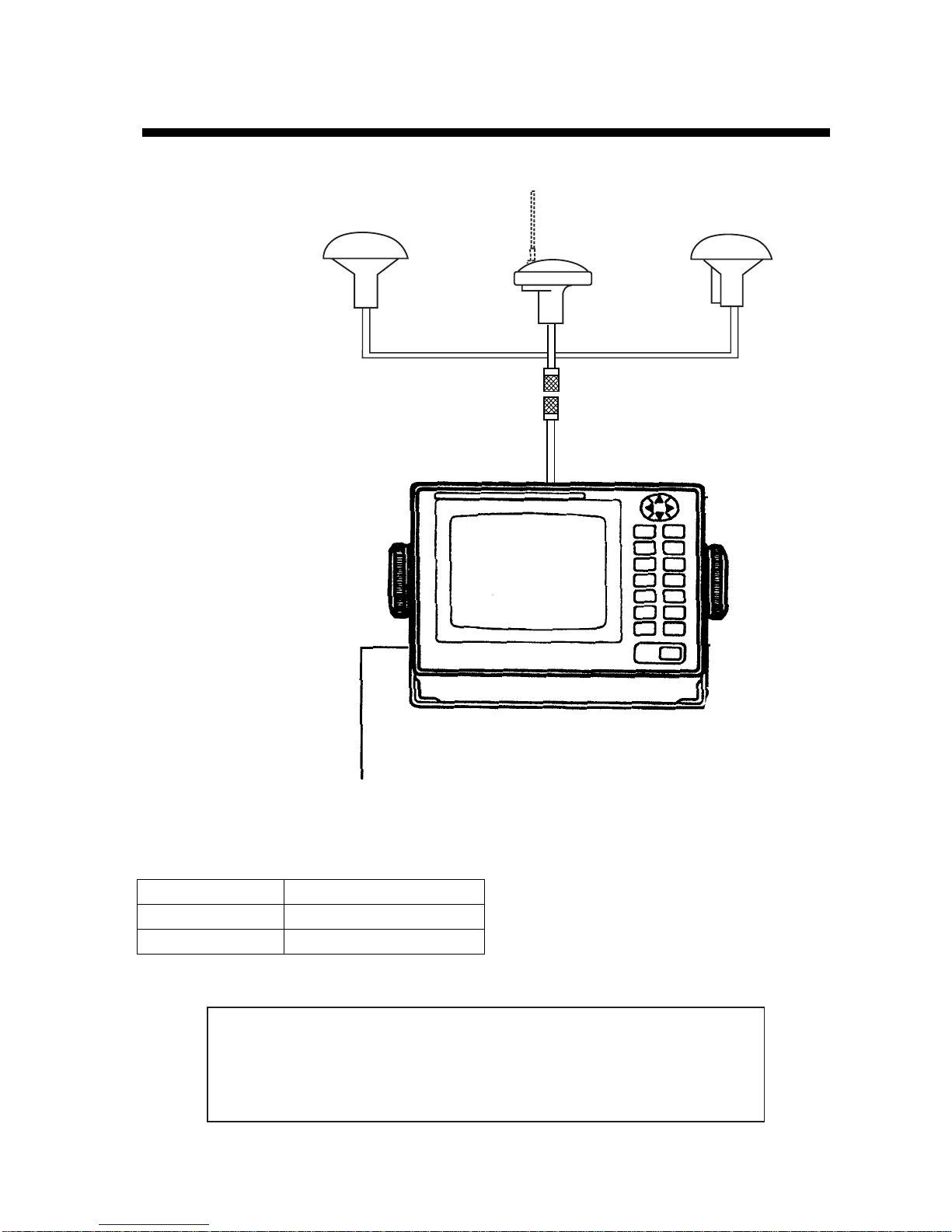
SYSTEM CONFIGURATION.................... iv
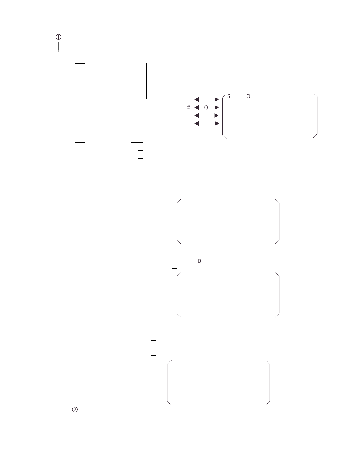
MENU TREE............................................. v
1. OPERATIONAL OVERVIEW
1.1 Control Description..........................1-1
1.2 Turning On and Off the Power .......1-2
1.3 Adjusting Display Contrast and
Brilliance...........................................1-3
1.4 Selecting the Display Mode.............1-3
1.5 Chart Icons ......................................1-6
2. TRACK
2.1 Enlarging/Shrinking the Display......2-1
2.2 Selecting Display Orientation..........2-1
2.3 Shifting the Cursor...........................2-1
2.4 Shifting the Display..........................2-2
2.5 Centering Cursor Position...............2-2
2.6 Centering Own Ship's Position........2-2
2.7 Stopping/Starting Plotting and
Recording of Track.........................2-2
2.8 Erasing Track...................................2-3
2.9 Selecting Track Plotting Interval......2-4
2.10Apportioning the Memory..............2-5
2.11 Selecting Bearing Reference.........2-6
3. MARKS
3.1 Entering/Erasing Marks...................3-1
3.2 Selecting Mark Shape.....................3-2
3.3 Connecting Marks
(selecting mark connection line) ....3-2
3.4 Entering Event Marks......................3-3
3.5 Selecting Event Mark Shape...........3-3
3.6 Entering the MOB Mark...................3-4
4. NAVIGATION PLANNING
4.1 Registering Waypoints.....................4-1
4.2 Editing Waypoints............................4-5
4.3 Deleting Waypoints..........................4-5
4.4 Registering Routes..........................4-6
4.5 Deleting Route Waypoints...............4-7
4.6 Replacing Route Waypoints............4-7
4.7 Deleting Routes...............................4-8
5. STARTING FOR DESTINATION
5.1 Setting Destination ..........................5-1
5.2 Canceling Destination......................5-5
5.3 Erasing Rout Waypoints (flags).......5-6
5.4 Finding Range and Bearing Between
Two Points......................................5-7
6. SETTING UP VARIOUS DISPLAYS
6.1 Selecting Data to Display on the
Data Display...................................6-1
6.2 Selecting Position Format ..............6-2
6.3 Demo Display..................................6-4
7. ALARMS
7.1 Arrival Alarm, Anchor Watch Alarm..7-1
7.2 Cross Track Error (XTE) Alarm .......7-2
7.3 Ship’s Speed Alarm .........................7-3
7.4 Trip Alarm ........................................7-3
7.5 Water Temperature Alarm................7-4
7.6 Depth Alarm.....................................7-4
7.7 WAAS/DGPS Alarm.........................7-4
8. MENU SETTINGS
8.1 GPS Menu.......................................8-1
8.2 Selecting Units of Measurement.....8-4
8.3 Mark, Character Size and Brilliance8-5
8.4 Settings for Connection of
Navigator........................................8-6
8.5 Receiving Data from Personal
Computer....................................8-8
8.6 WAAS/DGPS Setting.....................8-10
8.7 Displaying GPS Monitor Displays .8-12
9. MAINTENANCE & TROUBLESHOOTING
9.1 Clearing the Memory.......................9-1
9.2 Preventive Maintenance..................9-2
9.3 Error Messages...............................9-2
9.4 Troubleshooting...............................9-4
9.5 Diagnostic Tests ..............................9-5
APPENDIX
SPECIFICATIONS................................ A-1
DIGITAL INTERFACE
(IEC 61162-1 EDITION 2 (2000-07)).... A-3
TIME DIFFERENCES......................... A-20
GEODETIC CHART LIST................... A-21
LORAN C CHAINS............................. A-22
DECCACHAINS................................. A-23
GLOSSARY........................................ A-24
PARTS LIST........................................ A-27
INDEX.............................................Index-1
Declaration of conformity

iii
FOREWORD
A Word to GP-90 Owners
Congratulations on your choice of the
FURUNO GP-90 GPS Navigator. We are
confident you will see why the FURUNO
name has become synonymous with quality
and reliability.
For over 50 years FURUNO Electric
Company has enjoyed an enviable reputation
for innovative and dependable marine
electronics equipment. This dedication to
excellence is furthered by our extensive
global network of agents and dealers.
Your navigator is designed and constructed to
meet the rigorous demands of the marine
environment. However, no machine can
perform its intended function unless operated
and maintained properly. Please carefully
read and follow the recommended
procedures for operation and maintenance.
We would appreciate hearing from you, the
end-user, about whether we are achieving
our purposes.
Thank you for considering and purchasing
FURUNO equipment.
Features
The GP-90 GPS Navigator is a totally
integrated GPS receiver and video plotter
consisting of a display unit and an antenna
unit. The high sensitivity receiver tracks up to
12 satellites simultaneously. An 8-state
Kalman filter ensure optimum accuracy in
determination of vessel position, course and
speed.
In most cases the operator needs to do is to
turn on the power to find position.
The main features of the GP-90 are
• Comprehensive navigation data displays
• Storage for 999 waypoints and 30 routes
• Alarms: Waypoint Arrival, Anchor Watch,
Cross-track Error, Ship's Speed, Water
Temperature, Depth and Trip
• Man overboard feature records latitude and
longitude coordinates at time of man
overboard and provides continuous
updates of range and bearing to that point.
• DGPS capability - with built-in DGPS
beacon kit, or accepts DGPS correction
data from external DGPS beacon receiver
• Menu-driven operation
• Bright 122 x 92 mm LCD with temperature
compensated tone and brilliance
adjustment
• Power consumption is a low 10 W.
• Provision for connection of autopilot
(option) - steering data output to autopilot
• Digital display of water temperature and
depth with connection of video sounder
(with NMEA input)
• Memory stores 2,000 points of track and
marks.
• "Highway" display provides perspective
view.
• Position may be shown in latitude and
longitude or LOP (Loran or Decca).
• Four connectors for optional equipment
two IEC 61162-1/NMEA 0183 I/O, one IEC
61162-1/NMEA 0183 (or log) output and
one DGPS for personal computer I/O
• Fully meets the following regulation:
IMO MSC. 112(73) and IEC 61108-1.
Program No.
2051511-05.01 (September 2004)

i
v
SYSTEM CONFIGURATION
DISPLAY UNIT
Receives and processes
GPS signals to fix
position and display
it in latitude/longitude or LOP.
ANTENNA UNIT
Receives signal from
GPS satellite and/or
beacon reference station.
GPA-017S GPA-019S
(for DGPS)
GPA-018S
(for DGPS)
1.2 m Whip antenna
Ship’s Mains
12 to 24 VDC
CATEGORY OF UNITS
Unit Category
ANTENNA UNIT Exposed to weather
DISPLAY UNIT Protected from weather
This GPS receiver complies with Canadian standard RSS-210 (Low Power
License-Exempt Radio communication Devices).
Operation is subject to the following two conditions:
(1) this device may not cause interference, and
(2) this device must accept any interference, including interference that may
cause undesired operation of the device.

v
MENU TREE
Main menu
c
ESC
MENU 1. DISPLAY SETUP
2. TRACK/MARK SETUP
3. ERASE TRACK/MARK
4. ALARM SETTINGS
5. MANUAL CALCULATION
6.
7. GPS MONITOR SATELLITES MONITOR
BEACON RCVR MONITOR
STATION MESSAGE
From
To
Trial Speed (Auto, Man)
(010.0 kt)
XTE (On, Off)
Arrival/Anchor (Arr., Anc., Off)
Ship Speed (In, Over, Off)
Trip (CLR:Reset) (On, Off)
Water Temp. (In, Over, Off)
Depth (In, Over, Off)
Alarm Range (0.250 nm)
Alarm Range (0.500 nm)
Speed Range (011.0 - 015.0 kt)
Trip Range (0100.00 nm)
Temp. Range (+11.0 - +15.0 °C)
Depth Range (0011.0 - 0015.0 ft)
WAAS/DGPS (On, Off)
Erase Track (No, Yes)
Erase Mark (No, Yes)
Grid (Dark, Light, Off)
Course Bar (Dark, Light, Off)
Time Mark (Dark, Light, Off)
Waypoint Size (Large, Small)
Track Rec (Time, Dist)
Cursor Size (Large, Small)
Set/Drift Ave (Off, 10min, 20min, 30min,
1hour, 2hour, 3hour, 5hour, 6 hour)
,,,
Mark Shape ( )
Mark Line ( )
Event Mark ( )
8. SELF TESTS 1. Memory, I/O Port Test
2. Keyboard Test
3. Test Pattern
4. Automatic Testing

vi
1. PLOTTER SETUP
2. UNIT SETUP
4. DATA2 OUTPUT SETUP
5. DATA4 I/O SETUP
9. SYSTEM SETTINGS
Unit of Depth (m, ft, FA)
Unit of Temp. (°C, °F)
3. DATA1, 3 OUTPUT SETUP
Unit of Altitude (m, ft)
Unit of Distance (nm, km, sm)
Data (Out, Com., DGPS)
Data Fmt. (V1.5, V2.0, IEC)
Talker ID (GP, LC, DE)
Data4. Level (RS232C, RS422)
Output Data
Talker ID (GP, LC, DE)
Output Data
AAM: 00, APA: 00, APB: 04, BOD: 00,
BWR: 00, BWW: 00, GGA: 00, GLL: 01,
RMB: 01, RMC: 00, VTG: 01, WCV:00,
VDR: 00, WPL: 00, XTE: 00, ZDA: 01,
GNS: 00, GBS: 01, Rnn: 00, RTE: 00
AAM: 00, APA: 00, APB: 04, BOD: 00,
BWR: 00, BWW: 00, GGA: 00, GLL: 01,
RMB: 01, RMC: 00, VTG: 01, WCV:00,
VDR: 00, WPL: 00, XTE: 00, ZDA: 01,
GNS: 00, GBS: 01, Rnn: 00, RTE: 00
Data Fmt. (V1.5, V2.0, IEC)
Bearing Ref. (True, Mag)
Mag Variation (Auto, Man)
(07°W) (00°E)
User defined #1
t
RNG
u
#2
t
SOG
u
#3
t
BRG
u
#4
t
COG
u
SOG, COG, RNG, BRG,
W. TMP, W. DPT, XTE, dCOG,
AVR SOG, AVR COG, TTG, ETA,
TRIP, TRIP TM, RT. DIST, RT. TTG,
RT. ETA, ALT, VTD, DFT, SET, STW,
HDG
Memory Apportion (Trk: 1000/2000 Pt)
Calculation (RL, GC)
Talker ID (GP, LC, DE)
Output Data
AAM: 00, APA: 00, APB: 04, BOD: 00,
BWR: 00, BWW: 00, GGA: 00, GLL: 01,
RMB: 01, RMC: 00, VTG: 01, WCV:00,
VDR: 00, WPL: 00, XTE: 00, ZDA: 01,
GNS: 00, GBS: 01, Rnn: 00, RTE: 00
Data Fmt. (V1.5, V2.0, IEC)

vii
6. GPS SETUP
7. WAAS/DGPS SETUP
8. LOP SETUP
9. CLEAR MEMORY
Spd (0005, 0000 - 9999 sec)
Posn (0000, 0000 - 9999 sec)
ANT Height (016 ft, 000 - 999 ft)
Disable Satellite (1 - 32)
GPS Smoothing
Fix Mode (2D, 2/3D)
Speed Average (0060, 0000 - 9999 sec)
RAIM Function (Off, On)
RAIM Accuracy (100, 1 - 999)
Geodetic Datum (WGS84, NAD27, OTHER)
Posn Offset (0.000’N, 0.000’W)
Time Diff. (+00:00)
Posn (38°00.000’N, 123°00.000’W)
(001)
WAAS SEARCH
CORRECTIONS DATA SET (00)
MODE (GPS, WAAS, INT BEACON*, EXT BEACON*, AUTO)
LOP Display (LC, DE)
LC Chain (7980: 23 - 43)
r
LOP (+00.0 µs +00.0 µs)
Pos Display (Lat/Long, LOP)
DE Chain (24: G - P)
r
LOP (+0.00 Lane, +0.00 Lane)
Clear GPS (No, Yes)
Clear All (No, Yes)
Clear Plotter (No, Yes)
DGPS Station (Auto, Man (ID: 0274))
Freq. (323.0 kHz)
Baud Rate (25, 50, 100, 150, 200 bps)
(Auto, Man)
*: One is displayed according to kind of
beacon receiver used.

This page is intentionally left blank.

1-1
1. OPERATIONAL OVERVIEW
1.1 Control Description
Cursor pads
Shift display and
cursor.
Adjusts display contrast;
changes latitude/longitude
coordinate.
Turns power on/off.
Sets destination.
Deletes waypoints and marks;
clears wrong data; silences
audible alarm.
nlarges display.
Selects display orientation;
registers selections on menus.
Turns recording and plotting
of ship’s track on/off.
Inscribes mark on
the display.
MENU
ESC NU/CU
ENT
EVENT
MOB
WPT
RTE GOTO
MARK PLOT
ON/OFF
ZOOM
OUT
CENTER CURSOR
ON/OFF
TONE CLEAR
Inscribes event mark at
ship’s position; marks man
overboard position
Shrinks display.
Turns cursor on/off.
Centers ship’s position/cursor
position.
Registers waypoints
and routes.
Selects display mode.
Opens/closes menu;
quits current operation.
DISPLAY
SEL
ZOOM
IN
1
2
3
4
50
9
8
6
POWER
Figure 1-1 Control Panel

1. OPERATION
1-2
1.2 Turning On and Off the
Power
The GP-90 takes about 90 seconds to find
position when turned on for the very first time.
Thereafter it takes about 12 seconds to find
position each time the power is turned on.
Turning on the power
Press the [POWER] key.
The unit tests the PROGRAM MEMORY,
SRAM and battery for proper operation and
shows the results on the display. If equipped
with the internal beacon receiver, "BEACON
RCVR INSTALLED" appears at the bottom of
the display. The unit starts up with the last
used display mode.
PROGRAM MEMORY = OK
SRAM = OK
Internal Battery = OK
---
°
7°
D3D 100m
SAFE
34
°
23.456· N 135
°
45.678· E
BRG
RNG
123
12.3
SOG
kt
COG
[01]
30
40
20
50
H
2nm
BEACON RCVR INSTALLED
DATA 3 : DATA OUTPUT
GPS receiving
condition
Several seconds
later
WGS84
nm
Figure 1-2 Appearnace of display when
turning on the power
When turning on the power the following
occurs:
12 seconds after turning on the power,
accurate position (in latitude and longitude)
appears on the display.
If position could not be found, "NO FIX"
appears at the GPS receiving condition
window. When PDOP value exceeds 6 in the
3D mode or HDOP value exceeds 4 in the 2D
mode, "DOP" appears to indicate abnormal
fixing and the position indication could not be
updated.
When the satellite signal is being received
normally, one of the indications shown in
Table 1-1 appears depending on equipment
setting and GPS receiver state.
Table 1-1 GPS receiver indication
Equipment
setting GPS receiver state
indication
2D 2D (normal)
3D 3D (normal)
Differential 2D D2D (normal)
Differential 3D D3D (normal)
WAAS 2D W2D (normal)
WAAS 3D W2D (normal)
Note 1: When PDOP value exceeds 6 in the
3D mode, the position fixing method
is automatically changed to 2D.
Note 2: The "DEMO" icon appears when the
display is in the demonstration mode.
To return to normal mode, turn off
the power and turn it on while
pressing and holding down the
[NU/CU ENT] key.
Turning the power off
Press the [POWER] key.
The next time you turn on the power the unit
starts up with the last used display mode.

1. OPERATION
1-3
1.3 Adjusting Display
Contrast and Brilliance
1) Press the [TONE] key. The display shown
in Figure 1-3 appears.
Tone:
Brilliance:
[-] [+]
MENU : Escape
17 (0~31)
4 (0~4)
Figure 1-3 Screen for adjustment of display
contrast and brilliance
2) To adjust contrast, press or . Current
setting and setting range (0-31) are
shown to the right of " ".
To adjust brilliance, press or .
Current setting and setting range (0-4) are
shown to the right of " ".
Note 1: Operate cursor keys within 10
seconds after pressing the [TONE]
key. Otherwise, the screen for
adjustment of contrast and brilliance
will be cleared.
Note 2: If the display is turned off with
minimum tone the display will be
blank at the next power up. When
this occurs press the [TONE] key
continuously to adjust tone.
1.4 Selecting the Display
Mode
1) Press the [DISPLAY SEL] key. The
display shown in Figure 1-4 appears.
Plotter 1
Plotter 2
Highway
Navigation
Data
Select Display
Plotter 1
MENU : Escape
: Select
(DATUM: WGS-84)
* Shows currently selected geodetic chart
datum.
Figure 1-4 Screen for selection
of display mode
2) Press the [DISPLAY SEL] key, or
to select display mode. (When the
[DISPLAY SEL] key is pressed, the
display mode changes in sequence
shown below.) Selected display mode
appears about 15 seconds later.
Plo er 1 Plo er 2 Highway
Naviga ion
Da a
Sample displays of each display mode are
shown in the figures on the next several
pages.

1. OPERATION
1-4
Plotter 1 display
44
°
D3D 100m
SAFE
34
°
23.456´ N 135
°
45.678´ E
BRG
32
°
BRG TO +
11.5
RNG TO +
nm
123
°
COG
[01]
30
40
20
50
H
2.00 nm
Cursor position data,
when cursor is on
Own ship's
track Own ship
mark
Course
bar
Bearing from own ship
to destination waypoint
GPS receiving
condition
Alarm
range
Range from own ship
to destination waypoint,
or bearing from own
ship to cursor
Course
Grid
Cursor Speed, or range
from own ship
to cursor
Course
width
Course
Horizontal
range
WGS84
Distance for
RAIM reliability
RAIM
reliability*
*: For RAIM function, refer to page 8-1.
Figure 1-5 Plotter 1 display
Plotter 2 display
[01]
30
40
20
50
H
2.00 nm
Ship's position appears when cursor is off
D3D 100m
SAFE
34
°
23.456´ N 135
°
45.678´ E
WGS84
Figure 1-6 Plotter 2 display
Highway display
34
°
D3D 100m
SAFE
34
°
23.456´ N 135
°
45.678´ E
BRG
45
°
RNG
12.3
SOG
kt
0.35nm
COG
Course
Bearing from own ship to
detination waypoint
Position
Speed
Range from own ship to
destination waypoint
Own ship mark
Cross track error scale
North mak
WGS8
Figure 1-7 Highway display

1. OPERATION
1-5
Navigation display
1) No autopilot connection
E
3D
N
S
12.3
SOG
10.3
123
RNG
789
TRIP
nm
kt
VTD
kt
nm
BRG
23:45'
17H 45M
TO; 012
0.1nm 0.1nm
15
63
°
123
°
COG
ETA TTG
Bearing from own
ship to destination
waypoint
Time To Go
(3days17hrs45min)
Cross track
error scale
Cross track
error indication
Cross track
error meter
Destination
waypoint no. Speed
Bearing
scale Velocity To
Destination
Range from own
ship to destination
waypoint
Trip
distance
Estimated Time of
Arrival (15th23:45)
D3D 100m
SAFE
Figure 1-8 Navigation display,
no autopilot connection
2) With autopilot connection, automatic
mode
E
N
S
12.3
SOG
10.3
123
RNG
789
TRIP
nm
kt
VTD
kt
nm
BRG:
Auto
123
°
TO;
012
0.1nm 0.1nm
63
°
123
°
COG:
Auto Pilot Hdg
Auto mode
P 23
°
Str
Heading Rudder angleRudder angle
D3D 100m
SAFE
P: Port
S: Starboard
Figure 1-9 Navigation display, with autopilot
connection, automatic mode
3) Autopilot connection, modes other than
automatic mode (manual, nav, etc.)
E
N
S
12.3
SOG
10.3
123
°
AP CSE
789
TRIP
nm
kt
VTD
kt
BRG:
Man
123
°
TO; - - -
0.1nm 0.1nm
63
°
123
°
COG:
Auto Pilot Hdg
P 23
°
Str
Autopilot-set
course
Man: Manual mode
Nav: Nav mode
Other:---
Heading Rudder angle
D3D 100m
SAFE
Figure 1-10 Navigation display, with autopilot
connection, modes other than
the automatic mode

1. OPERATION
1-6
Data display
(Window assignment and size of characters
are user-definable)
SEP 12, 2003 23:59'59" U
12°23.456' N
123°23.456' E
POSITION
RNG
31.23
nm
SOG
12.3
kt
BRG
223.4°
COG
123.4°
TO : 001
MARINE
POINT1
NEXT
: 002
MARINE
POINT2
Position in latitude and U: UTC
J: JST
S: Ship's time
longitude or LOPs
Fixing date and time*
Cursor
User-defined
display window
User-defined
display data #1 User-defined
display data #4
User-defined
display data #3
User-defined
display data #2
Current destination waypoint
Next destination waypoint
WGS84
D3D 100m
SAFE
Figure 1-11 Data display mode
*: "- -" appears until calculating position after
turning on the power. If fixing error occurs
this indication stops.
1.5 Chart Icons
Various icons appear on the display to alert
you to equipment status.
: L/L position offset applied.
: Track recording turned off.
:Alarm is violated.
: North mark.
: Demonstration display.

2-1
2. TRACK
2.1 Enlarging/Shrinking the
Display
You may enlarge and shrink the display on
the Plotter 1 and Plotter 2 displays, with the
[ZOOM IN] and [ZOOM OUT] keys. The
horizontal range is available among 0.25, 0.5,
1, 2, 4, 8, 16, 32, 64, 128 and 192 nautical
miles for plotter 1 and 0.36, 0.71, 1.42, 2.84,
5.69, 11.38, 22.76, 45.51, 91.02, 182.04,
273.07 nautical miles for plotter 2 display.
The [ZOOM IN] key enlarges the display and
the [ZOOM OUT] key shrinks it. Each time a
zoom key is pressed the display range
appears at the center of the display for about
three seconds.
2.2 Selecting Display
Orientation
Display orientation can be selected on the
Plotter 1, Plotter 2 and Highway displays,
with the [NU/CU ENT] key. Two display
orientations are available: north-up and
course-up.
North-up display
In the north-up display, true north (0°) is at
the top of the display. Own ship moves on the
display in accordance with true speed and
true motion. Land is stationary.
Course-up display
Destination set
The destination is at the top of the display
and the north mark ( ) appears at the left
side of the display.
Destination not set
Ship's heading or course is at the top of the
display. The north mark appears at the left
side of the display.
2.3 Shifting the Cursor
The cursor can be shifted with the cursor
pads.
1) Press the [CURSOR ON/OFF] key to turn
on the cursor.
2) Press the cursor pads.
The cursor moves in the direction of the
cursor pads pressed. When the cursor
reaches the edge of the display, the display
shifts in the direction opposite.
Data and cursor state
Cursor state determines what data are shown
on the display.
Cursor turned on, cursor data
Cursor position is displayed in latitude and
longitude or LOPs (depending on menu
setting) at the top of the display. The range
and bearing from own ship to the cursor
appear at the right hand side of the display,
when in the Plotter 1 display.
234
°
BRG
345
°
BRG To +
123
°
11.5
RNG To +
nm
COG
2.0 nm
Cursor mark Cursor position in
latitude and longitude
Cursor Range from own
ship to cursor
Bearing from own
ship to cursor
34
°
23.456´ N 135
°
45.678´ E
WGS84
D3D 100m
SAFE
Figure 2-1 Data displayed when the cursor is
turned on

2. TRACK
2-2
Cursor turned off
Ship's position (in latitude and longitude or
LOPs), speed and course appear on the
display.
234
°
34
°
23.456´ N 135
°
45.678´ E
BRG
345
°
RNG
123
°
12.3
SOG
nm
kt
COG
Own ship
mark Own ship position
in latitude and longitude
Course
Speed
D3D 100m
SAFE
Figure2-2 Data display when the cursor is
turned off
2.4 Shifting the Display
The display can be shifted on the Plotter 1
and Plotter 2 displays, with the [CURSOR
ON/OFF] key. When own ship tracks off the
display it is automatically returned to the
screen center.
1) Press the [CURSOR ON/OFF] key to turn
off the cursor.
2) Press the cursor pads. The display shifts
in the direction of the cursor pads
pressed.
2.5 Centering Cursor
Position
1) Press the [CURSOR ON/OFF] key to turn
on the cursor.
2) Press the cursor pad to position the
cursor.
3) Press the [CENTER] key.
2.6 Centering Own Ship's
Position
1) Press the [CURSOR ON/OFF] key to turn
off the cursor.
2) Press the [CENTER] key.
2.7 Stopping/Starting
Plotting and Recording
of Track
The GP-90 stores 2,000 points of track and
marks. When the memory becomes full the
oldest track is erased to make room for the
latest.
Procedure
Press the [PLOT ON/OFF] key to start/stop
recording and plotting of track.
When plotting is resumed
"Resuming track plot" appears at the center
of the display for about three seconds.
When plotting is stopped
"Stopping track plot" appears at the center of
the display for about three seconds and "
H
"
appears at the left side of the display. ("
H
"
does not appear on the Navigation and Data
displays.)

2. TRACK
2-3
234
°
34
°
23.456· N 135
°
45.678· E
BRG
345
°
RNG
123
12.3
SOG
nm
kt
COG
H
Hold icon
(appears while recording
of track is stopped)
D3D 100m
SAFE
This portion of track
does not appear on
the display Own ship
Recording of
track started
Ship’s track
while recording is
stopped
Recording of track
turned off
Figure 2-3 Track not plotted or recorded when
plotting is stopped
2.8 Erasing Track
The track stored in the memory and
displayed on the screen can be erased.
CAUTION
Track cannot be restored once erased. Be
absolutely sure you want to erase all track.
1) Press the [MENU ESC] key. The MAIN
MENU appears.
AIN ENU
1. DISPLAY SETUP
2. TRACK/ ARK SETUP
3. ERASE TRACK/ ARK
4. ALAR SETTINGS
5. ANUAL CALCULATION
6.
7. GPS ONITOR
8. SELF TESTS
9. SYSTE SETTINGS
1. DISPLAY SETUP
ENT: Enter ENU: Escape
Figure 2-4 MAIN MENU
2) Press [3] to select ERASE TRACK/MARK.
ERASE TRACK/ ARK
Erase ark No
Erase Track No Yes
Yes
Track Pts. Used:
ark Pts. Used: 123/1000 Pt
345/1000 Pt
: Select
ENU: Escape
Figure 2-5 ERASE TRACK/MARK menu
3) Press or to select Erase Track.
4) Press to select Yes. The message
shown in Figure 2-6 appears.

2. TRACK
2-4
Are you sure to erase ?
ENT: Yes MENU: No
Figure 2-6 Prompt for erasure
of track
5) Press the [NU/CU ENT] key.
2.9 Selecting Track Plotting
Interval
The plotting interval determines both how the
track will be reconstructed on the display and
track storage time. A shorter interval
provides more accurate reconstruction of
track line, however total storage time is
reduced. The plotting interval can be selected
by time or distance. Plotting by distance
offers the advantage that the track is not
stored when the vessel is anchored.
Plotting interval by time
The setting range for plotting by time is 00 to
60 minutes.
1) Press the [MENU ESC] key.
2) Press [2] to display the TRACK/MARK
SETUP menu.
TRACK/MARK SETUP
Track Rec
Mark Shape
Mark Line
E ent Mark
Time
(01’00) Dist
(00.50nm)
: Select
ENT: Enter MENU: Escape
Figure 2-7 TRACK/MARK SETUP menu
3) Press or to select Track Rec.
4) Press to select Time.
5) Enter plotting interval in four digits. To
enter 30 seconds, for example, press [0]
[0] [3] [0].
6) Press the [NU/CU ENT] key.
7) Press the [MENU ESC] key.
Plotting interval by distance
The setting range for plotting by distance is
0.01 to 99.99 nautical miles. To plot all track,
enter 00.00.
1) Press the [MENU ESC] key.
2) Press [2] to display the TRACK/MARK
SETUP menu.
3) Press or to select Track Rec.
4) Press to select Distance.
5) Enter plotting interval. To enter 0.1
nautical miles, for example, press [0] [0]
[1].
6) Press the [NU/CU ENT] key.
7) Press the [MENU ESC] key.
Other manuals for GP-90
2
Table of contents
Other Furuno GPS manuals

Furuno
Furuno GP-31 User manual

Furuno
Furuno GP-39 User manual

Furuno
Furuno GPS Navigator GP-500 MARK-2 User manual

Furuno
Furuno GP-150 Manual

Furuno
Furuno GP-37 Manual

Furuno
Furuno GP-80 User manual

Furuno
Furuno GP-3700 User manual

Furuno
Furuno GP-39 Manual

Furuno
Furuno GP-80 Manual

Furuno
Furuno GP-150 User manual

Furuno
Furuno GP-30 Operators Manual

Furuno
Furuno GP-7000F User manual

Furuno
Furuno Felcom 82 Manual

Furuno
Furuno GP-1610C User manual

Furuno
Furuno GP-3700F User manual

Furuno
Furuno GP-80 User manual

Furuno
Furuno FAP-50 User manual

Furuno
Furuno GP-3500 User manual

Furuno
Furuno GP-7000 User manual

Furuno
Furuno GP170D User manual