Furuno VR-3000 User manual

The paper used in this manual
is elemental chlorine free.
FURUNO Authorized Distributor/DealerFURUNO Authorized Distributor/Dealer
9-52
A
shihara-cho,9-52
A
shihara-cho,
Nishinomi
y
a 662-8580, JAPANNishinomi
y
a 662-8580, JAPAN
Tele
p
hone :Tele
p
hone : 0798-65-21110798-65-2111
FaxFax 0798-65-42000798-65-4200
::
FIRST EDITION :FIRST EDITION : APR.APR. 20062006
Printed in JapanPrinted in Japan
A
ll ri
g
hts reserved.
A
ll ri
g
hts reserved.
CC :: JUL.JUL. 27, 200627, 2006
Pub. No.Pub. No. OME-44370OME-44370
*
0
0015707812*
*
0
0015707812*
*
0
0015707812*
*
0
0015707812*
(( TATATATA )) VR-3000/3000SVR-3000/3000S * 0 0 0 1 5 7 0 7 8 1 2 ** 0 0 0 1 5 7 0 7 8 1 2 *
*
O
ME
4
4370C00*
*
O
ME
4
4370C00*
*
O
ME
4
4370C00*
*
O
ME
4
4370C00*
* O M E 4 4 3 7 0 C 0 0 ** O M E 4 4 3 7 0 C 0 0 *
www.reelschematic.com

i
IMPORTANT NOTICE
• This manual is intended for use by native speakers of English.
• No part of this manual may be copied or reproduced without written permission.
• If this manual is lost or worn, contact your dealer about replacement.
• The contents of this manual and equipment specifications are subject to change without
notice.
• FURUNO will assume no responsibility for the damage caused by improper use or
modification of the equipment by an unauthorized agent or a third party.
• Store this manual in a convenient place for future reference.
• Dispose of the unit in accordance with local regulations.
www.reelschematic.com

ii
WARNING
ELECTRICAL SHOCK HAZARD
Do not open the equipment.
Only qualified personnel
should work inside the
equipment.
Do not disassemble or modify the
equipment.
Fire, electrical shock or serious injury can
result.
Immediately turn off the power
(BATTERY, DC and AC switches in
that order) at the DCU and also turn off
off the power at the ship's mains
switchboard if water leaks into the
equipment or the equipment is emitting
smoke or fire.
Continued use can cause fatal damage to
the equipment.
Only authorized personnel shall
disassemble the DRU.
Pressure may build up inside the unit when
it is subjected to fire or is retrieved from a
great depth.
Do not allow rain or water splash to
contact the equipment.
Fire or electrical shock can result.
SAFETY INSTRUCTIONS
WARNING
Do not disassemble the battery.
Battery fluid is harmful to the eyes and skin,
particularly the eyes. If the fluid contacts
skin or eyes, flush area with fresh water
and contact a physician immediately.
Do not dispose of the battery or acoustic
beacon in fire.
Those components may burst if disposed of
in fire. Further, dispose of the battery in
accordance with appropriate regulations.
Do not touch any electricaly conductive
parts.
Touching electrically conductive parts can
result in electrical shock. Use rubber gloves,
etc. when conducting inspection or
maintenance work.
Do not short battery terminals.
Short can lead to bursting or fire.
Do not:
- use batteries of different capacities
- mix old batteries with new
- mix batteries of different makes
Batteries themselves may become
damaged or damage to electrical
parts may result.
CAUTION
WARNING
To avoid electrical shock, do not
remove cover. No user-serviceable
parts inside.
WARNING LABELS
Warning labels are attached to the DCU.
Do not remove the labels. If the label is missing or
damaged, contact a FURUNO agent or dealer
about replacement.
Name: Warning Label 1
Type: 86-003-1011-2
Code No.: 100-236-232-10
WARNING
To avoid electrical shock, do not
remove cover. No user-serviceable
parts inside.
Name: Warning Label 2
Type: 03-129-1001-2
Code No.: 100-236-742-10
www.reelschematic.com

iii
POWERING DATA COLLECTING UNIT
On the power control panel in the Data Collecting Unit (DCU), confirm that the status display
shows “- - -“ and the NORMAL LED is lit after the power has been on for two minutes. If not, see
Chapter 3.
Procedure for turning on power
1. Turn the AC breaker switch on.
2. Turn the DC breaker switch on if DC power is connected.
3. Turn the BATTERY BACKUP breaker switch on.
NORMAL LED
Breaker switches (from left)
Battery Backup, DC, AC
Status Display
Power control panel/status display inside the DCU
Error indication on Remote Alarm Panel (RAP)
If the ERROR LED (red) lights on the RAP, check the error number on its status display and refer
to the error code tables in Chapter 3.
ERROR LED
Remote Alarm Panel
www.reelschematic.com

iv
IF AN INCIDENT OCCURS
Press the SAVE button on the RemoteAlarm Panel.
SAVE LED
(yellow)
SAVE button
• The SAVE LED (yellow) starts flashing and shortly thereafter lights. Then, recording to the
backup HDD in the Data Collecting Unit is stopped.
• Recording at the Data Recording Unit continues.
www.reelschematic.com

v
TABLE OF CONTENTS
FOREWORD................................................................................................................... vi
SYSTEM CONFIGURATION ......................................................................................... vii
RECORD OF PUB REV., PROG. NO............................................................................ viii
1. OPERATION...............................................................................................................1
1.1 Overview....................................................................................................................................1
1.2 Operating Procedure.................................................................................................................6
1.2.1 Powering, recording.........................................................................................................6
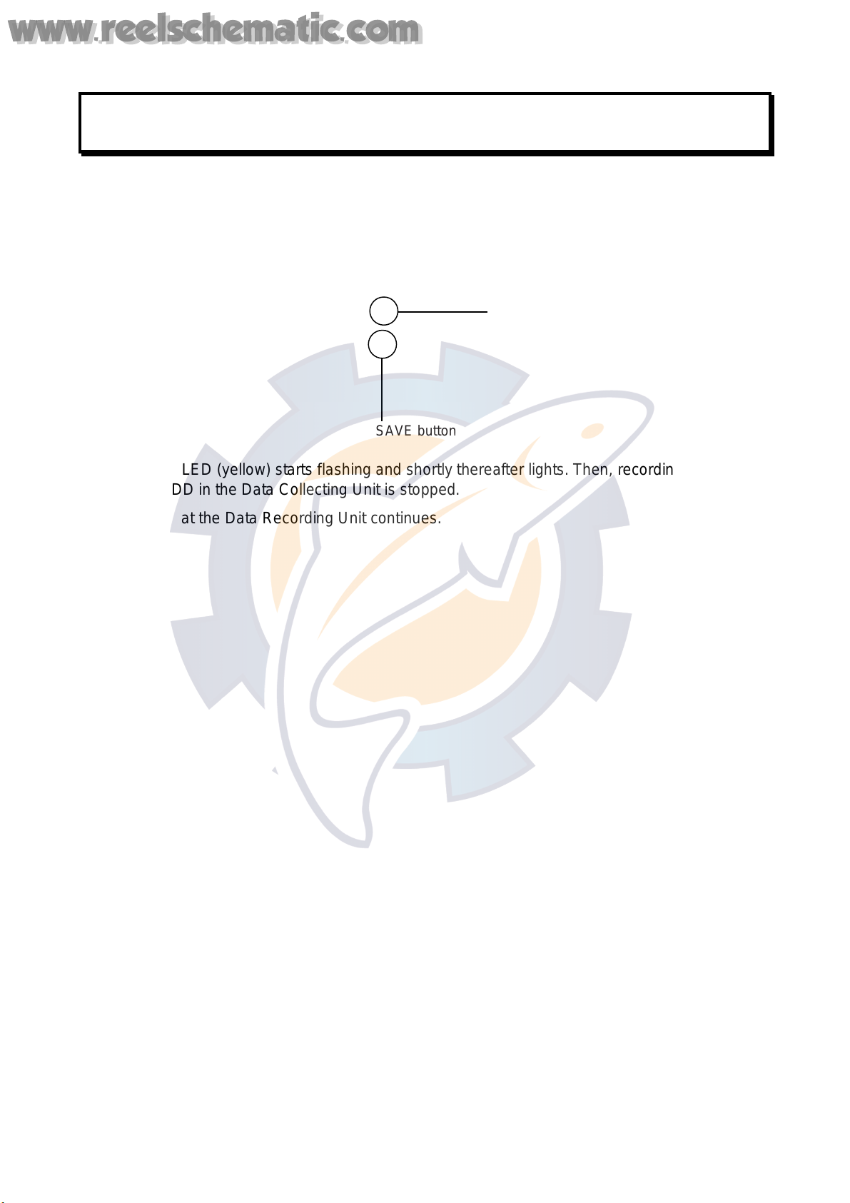
1.2.2 Stopping recording...........................................................................................................6
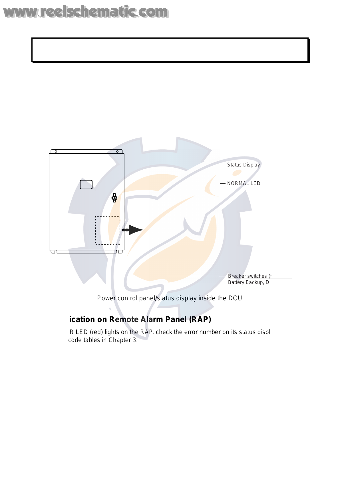
1.3 Operation on Remote Alarm Panel............................................................................................7
1.4 Removing HDD..........................................................................................................................8
1.5 How to Release DRU ................................................................................................................8
2. MAINTENANCE..........................................................................................................9
2.1 Annual Recertification................................................................................................................9
2.2 Cleaning.....................................................................................................................................9
2.3 Software Maintenance.............................................................................................................10
2.3.1 Software list ...................................................................................................................10
2.3.2 Checking software version of system program..............................................................10
2.3.3 Checking software version of RAP................................................................................10
2.4 Replacing Batteries..................................................................................................................11
2.5 Replacing Acoustic Beacon.....................................................................................................12
2.6 Replacing Backup HDD...........................................................................................................13
2.7 Replacing Fuses......................................................................................................................14
2.8 Replacing Consumable Parts..................................................................................................14
3. TROUBLESHOOTING..............................................................................................15
3.1 General Troubleshooting.........................................................................................................15
3.2 Error Codes .............................................................................................................................16
3.3 Testing Display of Remote Alarm Panel..................................................................................20
4. LOCATION OF PARTS.............................................................................................21
4.1 Parts Location..........................................................................................................................21
4.1.1 Data Collecting Unit (VR-3010) .....................................................................................21
4.1.2 Data Recording Unit (VR-5020-9G or VR-5020-6G).....................................................22
4.1.3 Junction Box (IF-8530) ..................................................................................................23
4.1.4 Remote Alarm Panel (VR-3016)....................................................................................23
4.2 Parts List..................................................................................................................................24
5. INTERFACE (IEC 61162-1, IEC 61162-2).................................................................25
5.1 Data Sentences .......................................................................................................................25
5.2 Interface Circuits......................................................................................................................38
5.2.1 IEC 61162-1...................................................................................................................38
5.2.2 IEC 61162-2...................................................................................................................39
APPENDIX: PLAYING BACK RECORDED DATA........................................................40
SPECIFICATIONS .....................................................................................................SP-1
www.reelschematic.com

vi
FOREWORD
A Word to the Owner of the VR-3000, VR-3000S
Thank you for purchasing the FURUNO Voyage Data Recorder (VDR) VR-3000, Simplified
Voyage Data Recorder (S-VDR) VR-3000S. We are confident you will discover why FURUNO
has become synonymous with quality and reliability.
What is a VDR, S-VDR?
A VDR records various data and events encountered aboard ship. The purpose of the VDR is to
help investigators locate the causes of marine incidents. There is no principle difference between
a VDR and an S-VDR. The difference is the amount of information required to be recorded. The
VDR is required to record more data than the S-VDR. Note that this manual refers to either the
VDR or S-VDR as VDR.
The revised SOLAS Chapter V requires the installation of VDRs on passenger ships of 150 GT
and above on all voyages and other ships of 3000 GT and above on international voyages and for
newly built ships on and after 1 July, 2002.
The basic VR-3000/VR-3000S consists of a Data Collecting Unit (DCU), a Data Recording Unit
(DRU), a Remote Alarm Panel (RAP) and microphones to record bridge audio. The VR-3000 is
also equipped with a Junction Box (JB), which is optional on the VR-3000S. The DCU contains
the Data Processor Unit, interface modules and backup batteries. It collects data from sensors as
required by the IMO and IEC standards. The DCU processes the incoming data and information
in the order of occurrence while old data is overwritten with new data for storage in the DRU for a
12 h period. The batteries supply power to the DCU to record bridge audio for 2 h in case of a
main ship’s power failure.
The flash memory in the DRU stores the data coming from the DCU. All essential navigation and
status data including bridge conversation, VHF communications, and radar images are recorded.
The data can be retrieved by using playback software for investigation after an incident. The DRU
components are embodied in the protective capsule. The capsule ensures survival and recovery
of the recorded data after an incident. An acoustical pinger helps locate the DRU underwater.
Features
• Reliable and fast data exchange between DCU and DRU via a single IEEE1394 cable.
• Easy commissioning and maintenance by PC downloading/uploading.
• 12-hour recording of normal sensor loading in standard memory.
• UTC time tagged for system synchronization and easy data retrieval.
• Choice of flash memory capacity in the Data Recording Unit.
• Backup hard disk (HDD) for storage and retrieval of data.
• Meets IMO A.861 (20), IEC 61996 and other relevant standards.
www.reelschematic.com

vii
SYSTEM CONFIGURATION
Max. 4 ch
Analog
(Max. 16 ch)
Digital (Max. 64 ch)
Max. 6 ch
Max. 2 ch
Serial (Max. 8)
Remote Alarm
Panel (RAP)
VR-3016
GPS
Speed log
Heading
Echosounder
Autopilot
Engine telegraph
Steering gear
M/E remote system
Main air compressor
Bow thruster
Shell door system
Watertight doors
Fire doors
Anemometer
Fire detection
Main alarms
Others
Data Collecting
Unit (DCU)
VR-3010
Radar I/F
RI-3010*
100-230 VAC
24 VDC
: Standard supply equipment and cable
: Optional supply equipment and cable
: Local supply equipment and cable
VHF Audio
Radar
VHF I/F
IF-5200
Bridge MIC
VR-5011
IEC 61162
serial data
Alarm Monitoring
System
Max.
2 ch
Live Player Pro
VR-5034
Junction Box (JB)
IF-8530*
Junction Box (JB)
IF-8530 (max. 2)
24 VDC
Serial
(1ch)
Serial (Max. 8 ch)
Analog
(Max. 16 ch)
Digital (Max. 64 ch)
Data Recording Unit (DRU)
VR-5020-6G/VR-5020-9G
Waterproof MIC
VR-3012W
* Optional with VR-3000S
Serial (1 ch)
Environmental category
DCU Protected from weather
DRU Exposed to weather
RAP Protected from weather
Bridge MIC Protected from weather
Waterproof MIC Exposed to weather
VHF I/F unit Protected from weather
JB Protected from weather
www.reelschematic.com

viii
RECORD OF PUB REV., PROG. NO.
Revision No.,
Date of Revision Program No.
(software) Outline of Revision
A
Apr. 19, 2006 VR-3000 SYSTEM
2450031-01
RAP
2450026-01
1st printing.
A1
June 2, 2006 Same as above Page vi, vii
Revised system configuration drawings to include
Waterproof MIC.
Page viii
Revised this page.
Page 16 – 17
Changed error code no. as follows:
035→034 Storage failure
041→042 Grabber failure
048→046 DRU Index error
SP-1 – SP-4
Revised specifications
B
June 16, 2006 Same as above All pages revised.
www.reelschematic.com

1
1. OPERATION
1.1 Overview
The VR-3000/VR-3000S consists of Data Collecting Unit (DCU), Data Recording Unit (DRU),
RemoteAlarm Panel (RAP), Junction Box (JB, optional supply with VR-3000S) and bridge
microphone units. The VDR system continuously stores data from the past 12 hours onto the
Flash Memory in the capsule, erasing the oldest data stored as new data is recorded. The data to
be recorded includes the following:
Parameters to be recorded IEC 61162 formatter Notes
Date and time ZDA
Ship’s position and datum used GNS and DTM
Speed (water and/or ground) VBW
Heading (true) HDT
Heading (magnetic) HDG
AIS-VHF data-link message VDM
AIS-VHF data-link own-vessel message VDO
Depth (echo sounder) DPT
Alarms ALR No requirement for S-VDR to
send alarm messages
Rudder order/response manual RSA
Rudder order/response automatic HTC, HTD
Engine order/response RPM, XDR
Hull openings, watertight doors XDR
Accelerations and hull stress XDR, ALR
Wind speed and direction MWV
VDR alarm output $VRALR
Radar data
Bridge audio
VHF communication audio
Power supply precaution
If ship’s mains power source (100-230 VAC) and emergency source fail, the VR-3000/VR-3000S
continues to record bridge audio for 2 h from backup batteries.
www.reelschematic.com

2
Continuity of storing data
The VDR should be provided with power to store data for 12 h on a first-in, first-out basis.
Recording is terminated only under the following circumstances:
a) During essential maintenance while the vessel is in port.
b) When the vessel is laid-up.
c) In case of emergency, when the backup HDD is removed.
Data Collecting Unit
The DCU mainly consists of Data Processor Unit and Power Control Panel. The DCU includes
two 12 V backup batteries with a lifetime of approximately four years. The DCU collects the data
from various sensors and radar and records them in the DRU and backup HDD.
Recording interval of data and audio is as follows:
- Radar video signal: every 15 seconds
- Bridge and VHF audio: real time
- IEC sentences: when received
-Analog and digital data: every second
Breaker switches (from left)
Battery Backup, DC, AC
Status Display
LEDs (from left)
SAVE (yellow):
When stopping the data
recording, this starts
blinking from OFF state,
then lights steadily.
If the HDD is disconnected,
this LED lights also.
NORMAL (Green):
On at normal operation.
ERROR (red):
Lights for error.
LEDs: Light (green) when respective power is applied.
www.reelschematic.com

3
Data Recording Unit
The Data Recording Unit is housed in a highly visible protective capsule which can withstand a
fire of 1100°C for 1 hour and deep-sea pressure of 6000 m.
The underwater acoustic beacon (pinger) on the capsule automatically transmits 10 ms pulses at
37.5 kHz for at least 30 days when it is submerged in water. The expected life of the beacon is 6
years. The DRU is connected to the Data Collecting Unit (DCU) with a non-halogen FireWire
cable (IEEE1394).
Underwater Acoustic Beacon
Data Recording Unit
Integrity
The recording integrity is ensured by continuous monitoring of power supply, record function, bit
error rate, and microphone functionality. Visual alarm is generated for malfunction of any of these.
Alarm status is also indicated by relay contacts.
Data items to be recorded
Date and time
Date and time are obtained from an external GPS navigator referenced to UTC. Time information
is recorded at intervals of 1 s. Without date and time data, no data except audio signal is
recorded.
Ship’s position and datum used
Latitude, longitude and datum are obtained from a GPS navigator, Loran-C receiver or other
EPFS or INS available on standard digital interface. The source of data is identifiable on
playback.
Speed (water and/or ground)
Speed through the water (STW) or speed over the ground (SOG) is recorded at intervals of 1 s.
The resolution is 0.1 kt. Transverse speed is also indicated when available on board.
Heading (true, magnetic)
Heading is recorded at intervals of 1 s to a resolution of 0.1°. The data is labeled G
(gyrocompass), GPS, GLONASS, MAG. If heading information is not available in IEC 61162
format, an appropriate interface may be necessary.
www.reelschematic.com

4
AIS-VHF data-link message, AIS-VHF data-link own-vessel message
Where there is no commercial off-the-shelf interface available to obtain radar data then AIS target
data shall be recorded as a source of information regarding other ships, otherwiseAIS
information may be recorded additionally as a beneficial secondary source of information on both
other and own ship.
The VDM message (UAIS VHF Data-link) shall be recorded in such a way that all target data
available from the onboardAIS are acquired. If the VDO message (UAIS VHF Data-link
Own-vessel report) is recorded, this shall be additional to the recording of individual sensor data.
Depth (echo sounder)
Depth under keel up to a resolution of 0.1 m as available on the ship is recorded.
Alarms
The status of all IMO mandatory alarms is recorded individually with ID number and time stamp.
Audible alarms from the alarm units are stored simultaneously by the bridge audio microphones.
Rudder order/response
Rudder order and response angles are recorded up to a resolution of 1° as available on the ship.
The rudder information is recorded. If more than one rudder is provided, the circuitry can be
duplicated.
Engine order/response
The DCU obtains the engine order and response from the engine telegraph or direct engine
control. The signal level is normally 0-10 V. The engine parameters with shaft revolution and
ahead/astern indicators are recorded to a resolution of 1 rpm.
All order and response from bow, stern, thruster, tunnel thrusters and controllable pitch propellers
shall be recorded. The S-VDR shall record this data if said serial data is available.
Hull openings, watertight doors
Inputs digital or RS-422 serial can be connected individually. The data is received at intervals of 1
s and stored with time stamps. Serialdata sentence XDR is received at a data rate of 1,200-9,600
baud.
Accelerations and hull stresses
The DCU obtains signals from appropriate hull stress and response monitoring devices. The
inputs are recorded individually and stored with time stamps. Serial data sentence XDR is
received at a data rate of 1,200-9,600 baud.
Wind speed and direction
The DCU obtains the signal from appropriate wind speed and direction sensor. The inputs are
recorded individually and stored with time stamps. Serial data sentence XDR is received at a data
rate of 1,200-9,600 baud.
VDR alarm output
There is no requirement for the S-VDR to send alarm messages. If, as an option, such messages
are sent then the appropriate sentence format is ALR.
www.reelschematic.com

5
Radar data
Radar image including range rings, EBLs, VRMs, plotting symbols, radar maps, parts of SENC,
voyage plan, and other essential navigational indications, is recorded in the DRU via the interface
in the DCU which is connected to the buffered video output of the radar display unit. One
complete picture frame is captured at intervals of 15 s.
The radar display complying with IEC 60936-1 should have a buffered output (VESA DMTS
compatible) with resolutions between 640 x 480 and 1280 x 1024, and can be directly connected
with the VDR. Scanning may be interlaced or non-interlaced.
Bridge audio
Up to six microphones are supplied as standard to record conversation at conning station, radar
display and chart table. If possible, the microphones should be positioned to capture the audio
from the intercom, public address system, and audible alarms on the bridge. The microphones
are labeled Mic1, Mic2, etc. Microphone captures conversation in the bridge, audio signals from
equipment and sound from machinery. The microphone generates a test beep every 12 hours
which is also recorded. The microphone picks up audio signals ranging from 150 to 6000 Hz.
Communications audio
A maximum of two VHF communications are recorded for both transmitted and received audio
signals. The VHF radio connections are labeled VHF1 and VHF2.
www.reelschematic.com

6
1.2 Operating Procedure
The VDR comes with a key to lock the DCU to protect against any unauthorized access. The key
must be kept securely after installation.
1.2.1 Powering, recording
On the power control panel in the DCU, turn on the AC SUPPLY MAINS, DC SUPPLY MAINS and
BATTERY BACK-UP switches in this order. Confirm that the NORMAL LED on the power control
panel and RAP lights. The VDR records data automatically in the DRU and backup HDD.
Breaker switches (from left)
Battery Backup, DC, AC
NORMAL LED
REMOTE ALARM PANEL
POWER CONTROL PANEL
NORMAL LED
1.2.2 Stopping recording
Recording is terminated only under the following conditions:
- During essential maintenance purposes while the vessel is in port.
- When the vessel is laid-up.
To stop recording, turn off the BATTERY BACKUP, DC SUPPLY MAINS and AC SUPPLY MAINS
switches in this order. DO NOT turn off the system by the main breaker while the BATTERY
BACKUP switch is on. If this is done, the system operates on the batteries. The system stops
after running on batteries after 2 hours.
www.reelschematic.com

7
1.3 Operation on Remote Alarm Panel
No power switch is provided on the Remote Alarm Panel; it is turned on and off by the power
switch on the DCU. When the ERROR LED (red) on the Remote Alarm Panel is on, identify the
error by checking code number in the error code tables in Chapter 3. The buttons on the Remote
Alarm Panel work as described in the figure below.
LEDs (from left)
SAVE (yellow):
Starts blinking from OFF state
when recording is stopped,
then lights steadily.
If the HDD is disconnected,
this LED lights also.
NORMAL (Green):
On at normal operation.
ERROR (red):
Lights for error.
TEST: Tests LCD.
Status Display
DIMMER:
Adjust panel backlighting;
display software version
no. (pressed together).
Buzzer
ACK: Silences buzzer.
SAVE: Stops recording onto the backup HDD.
See the NOTICE below.
Remote Alarm Panel
Note: The buzzer sounds every time the radar connected to the VDR is turned off. Press the
ACK button to silence the alarm.
NOTICE
After pressing the SAVE button, data will
not be recorded. Replace the HDD with
an initialized one, or contact a FURUNO
agent for necessary procedure.
SAVE button
The SAVE button functions to stop recording to the backup HDD in the DCU. If an incident occurs,
press this button to stop recording to the backup HDD, and then see paragraph 1.4 for how to
remove the HDD,
www.reelschematic.com

8
1.4 Removing HDD
VDR information is copied automatically into the backup hard disk drive (HDD) for more than 12
hours (max. 48 hours) and is then automatically written over with new data. Bring the HDD with
you after an incident if possible.
To remove the HDD, do the following:
1. Press the SAVE button (long press) on the RAP (Remote Alarm Panel). The yellow LED starts
blinking, showing that recording is being terminated.
2. Wait until the LED lights steadily.
3. Open the DCU with the key and turn off the power.
4. Pull the knob on the HDD door to open the door.
5. Disconnect the IEEE1394 cable.
6. Remove the HDD.
IEEE1394
Cable
Knob
HDD
HD
DCU, showing location of HDD
1.5 How to Release DRU
To remove the DRU from the bracket (cradle)
do the following:
1. Loosen the hand-tightened cap.
2. Pull the DRU cable straight out.
(The cable may be cut after an incident.)
3. Remove two snap pins and then two hinge
pins.
4. Lift the release levers.
2. DRU cable
1. Cap
3. Hinge pin
3. Snap pin
4. Release levers.
www.reelschematic.com

9
MIC COVER
2. MAINTENANCE
Periodic checks and maintenance are important for proper operation of any electronic systems.
This chapter contains maintenance instructions to be followed to obtain optimum performance
and the longest possible life of the equipment.Any maintenance must be executed by a suitably
qualified technician.
WARNING
ELECTRICAL SHOCK HAZARD
Do not open the equipment.
Only qualified personnel
should work inside the
equipment.
Do not disassemble or modify the
equipment.
Fire, electrical shock or serious injury can
result.
2.1 Annual Recertification
The VDR must undergo an annual performance test to recertify suitability. This test is conducted
by a test engineer certified by a relevant ship classification society, the content and procedure of
the test in accordance with the regulations of that society. For further details about the VDR
performance test, contact your ship classification society.
2.2 Cleaning
Dirt or dust may be removed from units with a soft cloth.
Fresh water-moistened cloth may be used to remove
stubborn dirt. DO NOT use any commercial cleaning
agents to clean any unit. They can remove paint and
markings. This is especially important with the
Waterproof Microphone VR-3012W. The watertight
integrity of the microphone will be compromised if any
commercial cleaning agent contacts the ventilation
sheet behind the MIC cover.
Waterproof microphone VR-3012W (bulkhead type)
www.reelschematic.com

10
2.3 Software Maintenance
2.3.1 Software list
The software and software version of the VR-3000/VR-3000S are as shown in the table below.
VR-3000/VR-3000S software list
Software name Software version Date
VR-3000 System Program 2450031-01 Mar 2006
VR-3000 RAP 2450026-01 Mar 2006
2.3.2 Checking software version of system program
Follow the procedure below to check software version of system program.
1. Start up a PC that usesWindows XP or Windows 2000 OS.
2. Change the IP address to 10.0.0.102 and the subnet address to 255.0.0.0.
3. Connect the cross LAN cable (supplied) between the LAN port on the PC and J14 (Live
Player) in the DCU of the VR-3000/VR-3000S.
4. Start up Internet Explorer.
5. Enter the HTTP address http:/10.0.0.100.
6. A pop-up window should appear. Click the Start button on the window.
7. The display shows “VR-3000 Web Configurator” (V-XX.XX)”. The number appearing in place
of the X which follows the V is the version number. (For example, 2450031-01: 01 is the
version number.) “2450031” does not change, therefore it is not displayed.
2.3.3 Checking software version of RAP
Push and hold down the RAP’s plus and minus buttons together. A three-digit number appears
(for example, “101”) and these digits are the version number.
www.reelschematic.com
Other manuals for VR-3000
5
This manual suits for next models
1
Table of contents
Other Furuno Measuring Instrument manuals