1
CONTENTS
Complete Set .......................................................................................................3
System Diagram...................................................................................................5
Installation Materials...................................................................................6 – 12
Accessories .......................................................................................................13
Spare Parts ................................................................................................14 – 18
CHAPTER 1 GENERAL DESCRIPTION................................................. 1-1 – 1-6
1.1 Selection of Installation Site ..........................................................................................1-1
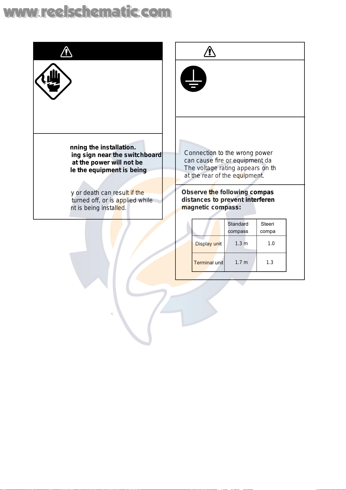
1.2 Grounding......................................................................................................................1-4
1.3Alteration of Power Supply Voltage ............................................................................... 1-6
CHAPTER 2 MOUNTING ...................................................................... 2-1 – 2-10
2.1 Display Unit ................................................................................................................... 2-1
2.2 Transceiver Unit............................................................................................................. 2-2
2.3 Matching Box/Junction Box ...........................................................................................2-3
2.4 Hull (Transducer) Unit for CI-35H .................................................................................. 2-4
2.5 DC-AC Inverter ..............................................................................................................2-8
2.6 Hull (Transducer) Unit for CI-35.....................................................................................2-9
CHAPTER 3 CONNECTIONS ............................................................... 3-1 – 3-16
3.1 Cabling ..........................................................................................................................3-1
3.2 Display Unit ................................................................................................................... 3-2
3.3 Transceiver Unit............................................................................................................. 3-3
3.4 Junction Box.................................................................................................................. 3-5
3.5 External Equipment .......................................................................................................3-7
3.5.1 Connection of external equipment to the display unit ........................................3-7
3.5.2 Connection of external to the transceiver unit.................................................... 3-8
3.6 DC-AC Inverter (TR-2450 or CSH-5050)..................................................................... 3-12
3.7 Matching Box...............................................................................................................3-15
CHAPTER 4 POST-INSTALLATION CHECK AND
ADJUSTMENT ................................................................. 4-1 – 4-25
4.1 Line Voltage...................................................................................................................4-1
4.2 LED Status Check .........................................................................................................4-4
4.3 DIP Switch Setting......................................................................................................... 4-9
4.4 TX Output Check ......................................................................................................... 4-14
4.5 External Noise and Interference Check.......................................................................4-15
4.5.1 External Noise Check....................................................................................... 4-15
4.5.2 Interference Check........................................................................................... 4-16
4.5.3 Interference Rejection ...................................................................................... 4-17
www.reelschematic.com
www.reelschematic.com