Furuno IF-2550 User manual

www.furuno.com
All brand and product names are trademarks, registered trademarks or service marks of their respective holders.
Installation Guide
Interface Unit
Model IF-2550
SAFETY INSTRUCTIONS ................................................................................................ i
OVERVIEW...................................................................................................................... 1
SYSTEM CONFIGURATION ........................................................................................... 1
EQUIPMENT LIST ........................................................................................................... 1
1. MODE AND FUNCTION .............................................................................................. 2
2. OVERVIEW OF MODE ................................................................................................ 2
3. FUSE REPLACEMENT ............................................................................................... 4
4. PROGRAM NO. ........................................................................................................... 4
5. MOUNTING.................................................................................................................. 4
6. CABLE FABRICATION ............................................................................................... 6
7. WIRING........................................................................................................................ 6
8. SETTING THE DIP SWITCHES ................................................................................ 11
9. THE SETTING OF THE JUMPER PINS.................................................................... 16
10. LED INDICATIONS.................................................................................................. 17
11. SENTENCE CONVERSION CHARTS .................................................................... 19
12. INTERFACES .......................................................................................................... 20
SPECIFICATIONS ..................................................................................................... SP-1
PACKING LISTS ......................................................................................................... A-1
OUTLINE DRAWINGS ................................................................................................ D-1
INTERCONNECTION DIAGRAMS.............................................................................. S-1

i
SAFETY INSTRUCTIONS
The operator and installer must read the applicable safety instructions before attempting to install
or operate the equipment.
Indicates a potentially hazardous situation which, if not
avoided, could result in death or serious injury.
Indicates a potentially hazardous situation which, if not
avoided, may result in minor or moderate injury.
WARNING
CAUTION
Warning, Caution Prohibitive Action Mandatory Action
WARNING
Turn off the power at the
switchboard before beginning
the installation.
Fire or electrical shock can result
if the power is left on.
CAUTION
Be sure that the power supply is
compatible with the voltage
rating of the equipment.
Connection of an incorrect power
supply can cause fire or damage
the equipment.
Use the proper fuse.
Use of an incorrect fuse may
damage the equipment.
Observe the following compass safe
distances to prevent interference to a
magnetic compass:
Standard
compass
IF-2550
Steering
compass
0.85 m 0.55 m
(Examples of symbols)
Model
Use only the specified power cable.
Fire or damage to the equipment can
result if a different cable is used.
Ground the equipment to prevent
electrical shock and mutual
interference.

1
OVERVIEW
The IF-2550 functions as an interface for the distribution of signal between the sensors (net sonde,
current indicator, and navigation equipment) and the display units for the sonar, fish finder, radar and
plotter.
SYSTEM CONFIGURATION
EQUIPMENT LIST
Name Type Code No. Qty. Remarks
Interface Unit IF-2550 - 1 Select from below.
・IF-2550-IEC1 (000-037-831,
For IEC61162-1)
・IF-2550-IEC2 (000-037-832,
For IEC61162-2)
Self Tapping
Screw
4x16 SUS304 000-162-605-10 4
Insulation Tube 3.0 x 0.3 YEL
*50CM*
000-162-841-10 4
Cable Tie CV-150-N 000-570-325 26
Glass Tube
Fuse
FGBO-A 250V
2A PBF
000-155-840-10 1
Interface Unit
IF-2550
Input㻌㻔Three ports㻕
TTYCSLA-1/TTYCSLA-4
12-24VDC
DPYC-1.5
Output (Nine ports)
TTYCSLA-1/TTYCSLA-4
Alarm
System
ALARM1 䡚3
TTYCSLA-1
Local ACK
Remote ACK
TTYCSLA-1
:
Standard supply
:
Optional or local supply
Radar
Plotter
Fishfinder
Sonar
Navigator
Current Indicator
Net-Sonde
Gyro Compass
Environmental Category
IF-2550: Protected from the weather

2
1. MODE AND FUNCTION
The IF-2550 is a unit that integrates the functions of the current interface units IF-1001, IF-2300, IF-
2500, IF-2503, and the distributor MD-550. Functionality of each model can be activated by setting
the appropriate DIP switches. DIP switch settings are outlined in Chapter 8.
The table below shows the comparison of each mode and function.
2. OVERVIEW OF MODE
The table below shows the overviews of each mode.
Mode
IF-2550 Functions ("〇" indicates availability)
NMEA
0183, CIF
Converting
NMEA
0183,
CIF Mix
GPS
DUAL
Alarm
System
AD-10
/NMEA0183
Data
distributing
Conver
ting
AD-10
to
NMEA
0183
NMEA0183
Data
inverting
IF-1001 〇------
IF-2300 - 〇-- - - 〇
IF-2500 - - 〇---
〇
IF-2503 - - - 〇-- -
MD-550 - - - - 〇〇 -
IF-2550 〇〇
-- - - -
Mode
Input/Output
Baud Rate NMEA
0183 Ver. Remarks
Input Output
IF-1001 1 8 4800 bps
(NMEA0183 to CIF)
2400bps/4800 bps
→4800 bps (CIF to
NMEA0183)
Ver.1.5/2.0 Mutual data converting
between CIF and
NMEA0183 is possible.
Baud rate of converting CIF
to NMEA0183 is switched by
DipSW1.
IF-2300 3 8 4800 bps (CIF)
4800 bps/38400 bps
(NMEA0183)
Ver.1.5/2.0/3.x/4.x
(Through)
Ver.2.0 ⇒Ver.1.5
(Switching)
Input data of CIF or
NMEA0183 can be mixed
and distributed output is
possible. Baud rate is
switched by DipSW1.
IF-2500 2 8 4800 bps/38400 bps
(NMEA0183)
Ver.1.5/2.0/3.x/4.x
(Through)
Data can be output as
NMEA0183 (IEC61162-1/2)
or Alarm contact signal.
Baud rate is switched by
DipSW1.

3
*1: A contact signal used for alarm management from an alarm-compatible device to an AMS (Alarm
Management System).
*2: A contact signal used by AMS (Alarm Management System) for alarm management for alarm-
compatible devices.
*3: Available when the contact signal is input from the REM / INV port.
*4: Set with DIPSW2 by connecting a single pole single throw switch (local supply) between pin 13
(REM / INV_H) and pin 14 (REM / INV_C) of TB4 so that current flows only when the switch is closed.
It is also possible to invert the sentence of the target.
IF-2503 1 8 4800 bps/38400 bps
(NMEA0183)
Ver.1.5/2.0/3.x/4.x
(Through)
Supports Local ACK * 1 and
Remote ACK * 2. System
fail/Data through/Alarm
output control /Internal
status output/Remote ACK
input functions can be used.
Baud rate is switched by
DipSW1.
MD-550 1 8 4800 bps to 38400
bps (NMEA0183)
Ver.1.5/2.0/3.x/4.x
(Through)
Not only IEC61162-1/2
standard signal distribution
but also AD-10 four
distribution is possible.
Supports One input, Four
outputs, Two lines and One
input Eight outputs and One
line. The setting of the baud
rate setting is not required.
IF-2550 1 8 4800 bps
(NMEA0183 to CIF)
2400 bps/4800 bps
(CIF to NMEA0183)
Ver.1.5/2.0
(Selecting by
DIPSW1)
Mutual data converting
between CIF and
NMEA0183. Inputted CIF or
NMEA0183 data can be
mixed and outputted.
Converting
AD-10 to
NMEA0183
1 8 38400bps
(NMEA0183)
Ver.1.5/2.0/3.x/4.x
(Through)
Converting AD-10 to
NMEA0183 (HDT, VWH) .
Sentence
inverting*3*4
3 8 Either IF-2300 or
IF-2500 settings
Either IF-2300 or
IF-2500 settings
When the ship turns 180 °,
the following sentences
whose bow direction is the
reference for measurement
are converted to the bow
direction after the turning.
・HCR, HDG, HDM, HDT,
THS
・VBW
・GPatt
・MWV, VWR, VWT
Mode
Input/Output
Baud Rate NMEA
0183 Ver. Remarks
Input Output

4
3. FUSE REPLACEMENT
If the fuse has blown, contact your dealer.
4. PROGRAM NO.
System:7850001-01.**
Application:7850004-01.**
** denotes minor modifications.
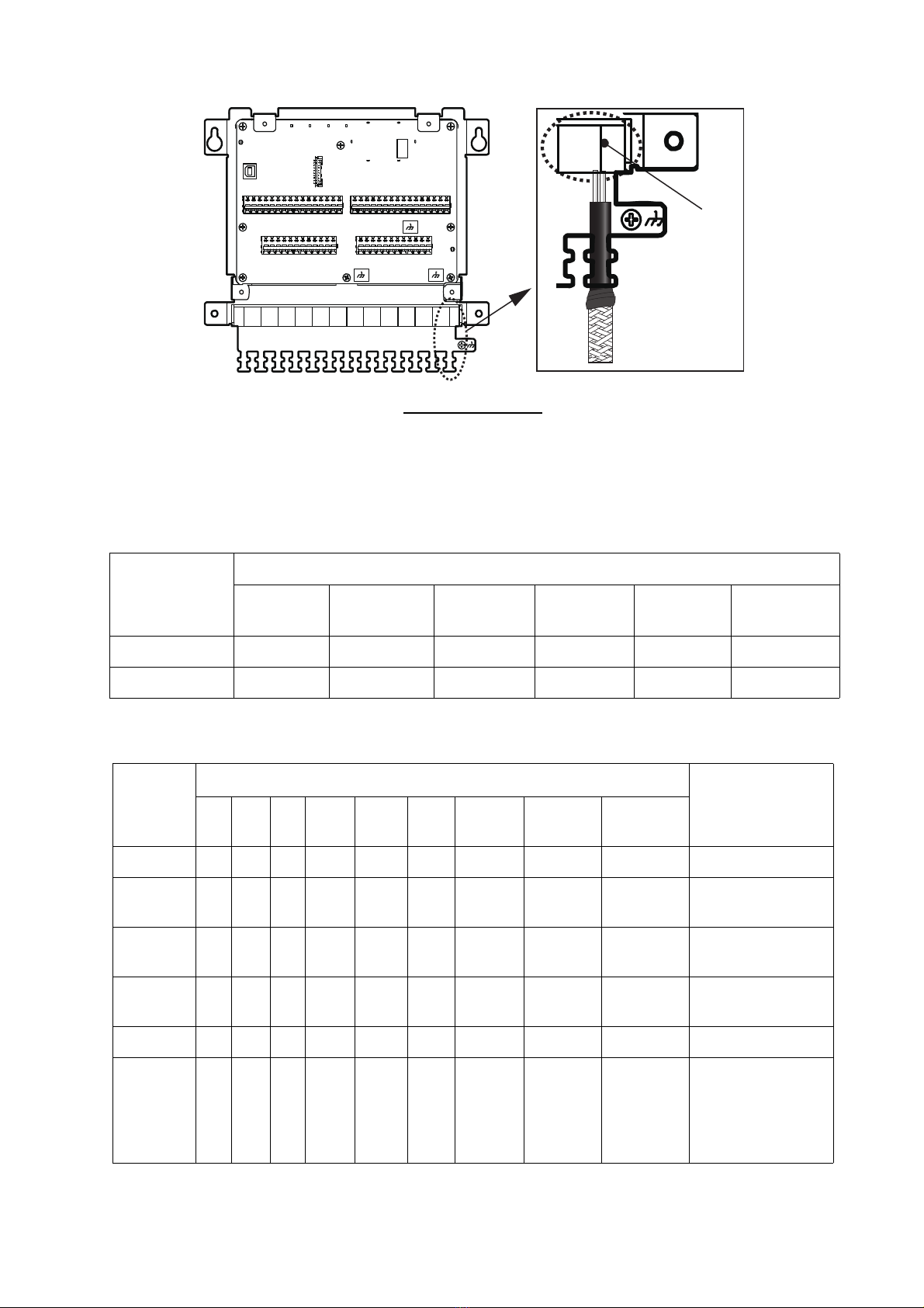
Program No. is also inscribed on the MPU (Micro-processing unit) of the board (See below figure).
The location of the MPU
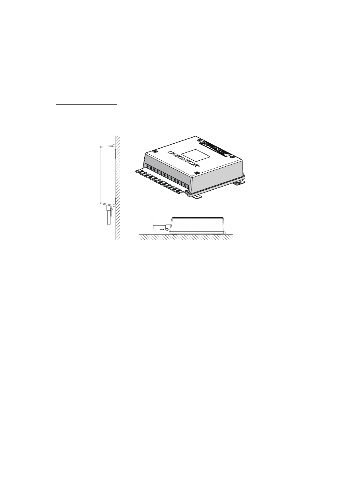
5. MOUNTING
Precautions
This unit does not have power switch. If the IF-2550 is not connected directly to a switchboard or cir-
cuit-breaker, install an external power switch (local supply) near the IF-2550.
When selecting a mounting location, keep in mind the following points.
• Use the specified cable for connecting.
• The power cable is to be supplied locally. Refer to “Cable Fabication” of this manual.
• Observe the compass safety distances and secure the distance.
• To prevent noise from the transceiver, do not tie the unit and transceiver cable with a cable tie.
• Turn off the power switch at the switchboard before proceeding with the mounting and wiring.
• Following tools are required for mounting
• Phillips-head screw driver(M3/M4)
• Hook spanner (236-332, located on the back of the unit cover)
• Mount the unit in the direction indicated in the outline drawing.
• When you mount the unit, secure the necessary service space. If service space is not secured,
maintenance cannot be done.
• The contact signal has a logical setting for both input and output. Make the settings according to
the connected device. The factory settings are all default settings.
• When you change the setting, restart the unit.
• The following concern acts as our importer in Europe, as defined in DECISION No 768/2008/EC.
- Name: FURUNO EUROPE B.V.
- Address: Ridderhaven 19B, 2984 BT Ridderkerk, The Netherland
MPU

5
• The following concern acts as our importer in UK, as defined in SI 2016/1025 as amended SI
2019/470.
- Name: FURUNO (UK) LTD.
- Address: West Building Penner Road Havant Hampshire PO9 1QY, U.K .
• Discard this product according to local regulations for the disposal of industrial waste. For disposal
in the USA, see the homepage of the Electronics Industries Alliance (http://www.eiae.org/) for the
correct method of disposal.
Mounting Procedure
This unit can be mounted on a desktop or bulkhead.Refer to the precautions and outline drawing at
the back of this manual when you mount the unit.
Mounting
1. Referring to the outline drawing, make four pilot holes for self-tapping screws (4x20, sup-
plied) in the mounting location.
2. Screw two self-tapping screws to the pilot holes, leaving a gap of 5mm.
3. Hang the unit on the screws and secure the unit by fastening the self-tapping screws.
Bulkhead
Mounting
Tabletop
Mounting
Overview

6
6. CABLE FABRICATION
Use the TTYCSLA-1, TTYCSLA-4 (Japan Industrial Standard cables) or the
equivalents.
7. WIRING
The procedure of the wiring is as follows;
1. Unfasten the four screws, then remove the cover.
NOTE: The connector sheet and hook spanner (239-332) are attached to the back of the cov-
er. Take care not to lose them.
Back of the cover
3
3
4040
Attach the crimp-on lug to the core.*
Vinyl tape
Pass the Insulation Tube (supplied) onto the
drain wire.
Drain wireDrain wire
Armor Inner sheath
190 䠄TB1/TB4䠅
160 䠄TB2/TB3䠅
190 䠄TB1/TB4䠅
160 䠄TB2/TB3䠅
150 䠄TB1/TB4䠅
120 䠄TB2/TB3䠅
150 䠄TB1/TB4䠅
120 䠄TB2/TB3䠅
*: For IF-2550-IEC2 only.
Hook Spanner
㸦236-332㸧
Connector
Sheet

7
2. Insert the fabricated cable to the cable packing (See following figure).
Inserting the cable
Note 1: The IF-2550 has different connectable ports and compatible standards
depending on the specifications and the mode to be set.
The following table shows the supported standards for each port, based on the IF-2550 spec-
ification
Note 2: Fabricated cables should be connected to their appropriate ports, indicated with a " ○
" in the following table.
Specification
Ports
IN1 IN2 IN3 OUT
1~4
OUT
5~8OUT9
IF-2550-IEC1 IEC61162-1 IEC61162-1 IEC61162-1 IEC61162-1 IEC61162-1 IEC61162-1
IF-2550-IEC2 IEC61162-2 IEC61162-2 IEC61162-2 IEC61162-2 IEC61162-1 IEC61162-1
Modes
Ports (〇: Available /-: Not Available)
Remarks
IN1 IN2 IN3 OUT
1~4
OUT
5~8
OUT
9
ALARM
1~3
LOCAL_
ACK
REMOTE_
ACK/INV
IF-1001 - - 〇〇 〇 -- - -
IF-2300 〇〇〇 〇 〇 -- - 〇Input gives priority
to IN1.
IF-2500 〇〇 -〇〇 -〇-〇Input gives priority
to IN1.
IF-2503 - - 〇〇 〇 〇 〇 〇 〇 P sentense outputs
from OUT9.
IF-2550 〇〇〇 〇 〇 -- - -
MD-550
(Setting:
OFF)
〇〇 -〇〇 -- - -
Converting AD-10
to NMEA 0183.
Connect IN1 to
data and IN2 to
shift.
Cable
packing

8
3. Referring to the following figure and table, connect the cables to terminals TB1 through TB4.
MD-550
(Setting:
ON)
〇〇 -〇〇 -- - -
One input, Four
outputs and Two
lines.
Data input / output
is as follows:
IN1→OUT1 to 4
IN2→OUT5 to 8
〇--〇〇 -- - -
One input, Eight
outputs and
One line.
TB 1 Terminal No. Functions TB 2 Terminal No. Functions
IN 1 (DATA) TB 1-1 RD1-H OUT 1 (DATA) TB 2-1 TD1-A
TB 1-2 RD1-C TB 2-2 TD1-B
TB 1-3 FG/ISO_GND* TB 2-3 FG/ISO_GND*
IN 2 (SHIFT) TB 1-4 RD2-H OUT 2 (DATA) TB 2-4 TD2-A
TB 1-5 RD2-C TB 2-5 TD2-B
TB 1-6 FG/ISO_GND* TB 2-6 FG/ISO_GND*
IN 3 TB 1-7 RD3-H OUT 3 (DATA) TB 2-7 TD3-A
TB 1-8 RD3-C TB 2-8 TD3-B
TB 1-9 FG/ISO_GND* TB 2-9 FG/ISO_GND*
OUT9 TB 1-10 ALM-TD-A OUT 4 (DATA) TB 2-10 TD4-A
TB 1-11 ALM-TD-B TB 2-11 TD4-B
TB 1-12 FG TB 2-12 FG*
TB 1-13 N.C.
12-24 VDC TB 1-14 DC_IN (+) TB 4 Terminal No. Functions
TB 1-15 N.C. ALARM 1 TB 4-1 ALM1-H
TB 1-16 DC_IN (-) TB 4-2 ALM1-C
TB 4-3 FG
TB 3 Terminal No. Functions
OUT 5 (SHIFT) TB 3-1 TD5-A ALARM 2 TB 4-4 ALM2-H
TB 3-2 TD5-B TB 4-5 ALM2-C
TB 3-3 FG TB 4-6 FG
OUT 6 (SHIFT) TB 3-4 TD6-A ALARM 3 TB 4-7 ALM3-H
TB 3-5 TD6-B TB 4-8 ALM3-C
TB 3-6 FG TB 4-9 FG
Modes
Ports (〇: Available /-: Not Available)
Remarks
IN1 IN2 IN3 OUT
1~4
OUT
5~8
OUT
9
ALARM
1~3
LOCAL_
ACK
REMOTE_
ACK/INV
TB1
TB2
TB3
TB4
How to connect wires to WAGO connector
Procedure
1. Twist core.
2. Insert terminal opener and
push.
3. Insert wire into hole. Be
careful not to pinch the
sheath.
4. Release terminal opener.
5. Pull wire to confirm it is
correctly inserted.
Wire
Twist
PushPushPush
Terminal
opener
WAGO
connector

9
*: In the IF-2550-IEC2, secure to spacers (see figure in NOTE 2 about the position).
NOTE 1: To avoid damage to the cables, pass the cables under the coating clip.
Coating Clip
NOTE 2: For IF-2550-IEC2 only, drain wires must be secured at the locations indicated in the
following figure and table.
The location of spacers
TB 3 Terminal No. Functions TB 4 Terminal No. Functions
OUT 7 (SHIFT) TB 3-7 TD7-A LOCAL_ACK TB 4-10 LOC-ACK-H
TB 3-8 TD7-B TB 4-11 LOC-ACK-C
TB 3-9 FG TB 4-12 FG
OUT 8 (SHIFT) TB 3-10 TD8-A REMOTE_ACK
/INV
TB 4-13 REM/INV-H
TB 3-11 TD8-B TB 4-14 REM/INV-C
TB 3-12 FG TB 4-15 FG
-TB 4-16 FG
Coating Clip CS-5U
䠄Secured to the board, See figure to the right䠅
Coating Clip
CS-5U
Spacer No. Drain wires
Spacer 1 OUT 1 and OUT 2.
Spacer 2 OUT 3 and OUT 4.
Spacer 3 IN 1, IN 2 and IN 3.
Spacer 1
Spacer 3
Spacer 2

10
4. Secure the cable to the cable clamp with two cable ties per cable (supplied, see following
figure).
The securing position of the cable
5. Depending on the installation and configuration, do one of the following:
・No DIP switch or Pin setting required; LED check not required: Fit the cover
then fasten the four screws removed at step 1.
・To Check the LED, see “10. LED INDICATIONS”.
・To set the jumper pins, see "9. SETTING THE JUMPER PINS".
・To set the DIP switches, see "8. SETTING THE DIP SWITCHES".
Cable
ties

11
8. SETTING THE DIP SWITCHES
The location of the DIP Switches
Set the DIP switches referring to the below table to set baud rate and mode.
All DIP switches are set to OFF as factory default.
Function Mode DipSW1 DipSW2 Remarks
Converting
NMEA0183 to
Contact signal
IF-2500 OFF OFF NMEA0183 Baud rate: 4800bps
Contact Signal: Normal Close
ON:7 OFF NMEA0183 Baud rate: 38400bps
Contact Signal: Normal Close
ON:4 OFF NMEA0183 Baud rate: 4800bps
Contact Signal: Normal Open
ON:4, 7 OFF NMEA0183 Baud rate: 38400bps
Contact Signal: Normal Open
IF-2503 ON:3 OFF NMEA0183 Baud rate: 4800bps
Contact Signal: Normal Close
ON:3, 7 OFF NMEA0183 Baud rate: 38400bps
Contact Signal: Normal Close
ON:3, 4 OFF NMEA0183 Baud rate: 4800bps
Contact Signal: Normal Open
ON:3, 4, 7 OFF NMEA0183 Baud rate: 38400bps
Contact Signal: Normal Open
Converting
NMEA0183 to CIF
IF-1001 ON:1, 4 OFF NMEA0183 Baud rate: 4800bps
GP sentence talker: From GP to GP
CIF Baud rate: 4800bps
ON:1, 4, 6 OFF NMEA0183 Baud rate: 4800bps
GP sentence talker: From GP to TR
CIF Baud rate: 4800bps
Dip SW 1/2

12
Converting
NMEA0183 to CIF
IF-1001 ON:1, 4, 5 OFF NMEA0183 Baud rate: 4800bps
GP sentence talker: From GP to LA
CIF Baud rate: 4800bps
ON:1, 4, 5,
6
OFF NMEA0183 Baud rate: 4800bps
GP sentence talker: From GP to LC
CIF Baud rate: 4800bps
Converting CIF to
NMEA0183
ON: 1 OFF CIF Baud rate: 4800bps
NMEA0183 Baud rate: 4800bps
Output NMEA 0183: Ver. 2.0
ZDA sentence talker: II
ON: 1, 6 OFF CIF Baud rate: 2400bps
NMEA0183 Baud rate: 4800bps
Output NMEA 0183: Ver. 2.0
ZDA sentence talker: II
ON: 1, 6, 8 OFF CIF Baud rate: 2400bps
NMEA0183 Baud rate: 4800bps
Output NMEA 0183: Ver. 2.0
ZDA sentence talker: GP
ON: 1, 8 OFF CIF Baud rate: 2400bps
NMEA0183 Baud rate: 4800bps
Output NMEA 0183: Ver. 2.0
ZDA sentence talker: II
ON: 1, 5 OFF CIF Baud rate: 4800bps
NMEA0183 Baud rate: 4800bps
Output NMEA 0183: Ver. 1.5
ZDA sentence talker: II
ON: 1, 5, 8 OFF CIF Baud rate: 2400bps
NMEA0183 Baud rate: 4800bps
Output NMEA 0183: Ver. 1.5
ZDA sentence talker: II
ON: 1, 5, 6 OFF CIF Baud rate: 4800bps
NMEA0183 Baud rate: 4800bps
Output NMEA 0183: Ver. 1.5
ZDA sentence talker: GP
ON: 1, 5,
6, 8
OFF CIF Baud rate: 2400bps
NMEA0183 Baud rate: 4800bps
Output NMEA 0183: Ver. 1.5
ZDA sentence talker: GP
Mixing NMEA0183
or CIF
IF-2300 ON: 2 OFF Output NMEA0183: Ver. 1.5, 2.0, 3.0, 4.0
and 4.1
NMEA0183 Baud rate: 4800bps
Contact Signal: Normal Close
Function Mode DipSW1 DipSW2 Remarks

13
Mixing NMEA0183
or CIF
IF-2300 ON: 2, 7 OFF Output NMEA0183 : Ver. 1.5, 2.0, 3.0, 4.0
and 4.1
NMEA0183 Baud rate: 38400bps
Contact Signal: Normal Close
ON: 2, 6 OFF Output NMEA0183: Ver. 2.0→Ver. 1.5
NMEA0183 Baud rate: 4800bps
Contact Signal: Normal Open
ON: 2, 6, 7 OFF Output NMEA0183: Ver. 2.0→Ver. 1.5
NMEA0183 Baud rate: 38400bps
Contact Signal: Normal Open
ON: 2, 5 OFF Output NMEA0183: Ver. 2.0→Ver. 1.5
NMEA0183 Baud rate: 4800bps
Contact Signal: Normal Close
ON: 2, 5, 6 OFF Output NMEA0183 : Ver. 2.0→Ver. 1.5
NMEA0183 Baud rate: 38400bps
Contact Signal: Normal Open
ON: 2, 5,
6, 7
OFF Output NMEA0183 : Ver. 2.0→Ver. 1.5
NMEA0183 Baud rate: 4800bps
Contact Signal: Normal Open
ON: 2, 5, 7 OFF Output NMEA0183 : Ver. 2.0→Ver. 1.5
NMEA0183 Baud rate: 38400bps
Contact Signal: Normal Close
Mixing CIF ON: 2, 4 OFF CIF Baud rate: 4800bps
Converting CIF to
NMEA0183
Mixing NMEA0183
converted from CIF
IF-2550 ON: 1, 2 OFF CIF Baud rate: 4800bps
NMEA0183 Baud rate: 4800bps
Output NMEA 0183: Ver. 2.0
ZDA sentence talker: II
ON: 1, 2, 8 OFF CIF Baud rate: 2400bps
NMEA0183 Baud rate: 4800bps
Output NMEA 0183: Ver. 2.0
ZDA sentence talker: II
ON: 1, 2, 6 OFF CIF Baud rate: 4800bps
NMEA0183 Baud rate: 4800bps
Output NMEA 0183: Ver. 2.0
ZDA sentence talker: GP
Function Mode DipSW1 DipSW2 Remarks

14
Converting CIF to
NMEA0183
Mixing NMEA0183
converted from CIF
to NMEA0183
IF-2550 ON: 1, 2,
6, 8
OFF CIF Baud rate: 2400bps
NMEA0183 Baud rate: 4800bps
Output NMEA 0183: Ver. 2.0
ZDA sentence talker: GP
ON: 1, 2, 5 OFF CIF Baud rate: 4800bps
NMEA0183 Baud rate: 4800bps
Output NMEA 0183: Ver. 1.5
ZDA sentence talker: II
ON: 1, 2,
5, 8
OFF CIF Baud rate: 2400bps
NMEA0183 Baud rate: 4800bps
Output NMEA 0183: Ver. 1.5
ZDA sentence talker: II
ON: 1, 2,
5, 6
OFF CIF Baud rate: 4800bps
NMEA0183 Baud rate: 4800bps
Output NMEA 0183: Ver. 1.5
ZDA sentence talker: GP
ON: 1, 2,
5, 6, 8
OFF CIF Baud rate: 2400bps
NMEA0183 Baud rate: 4800bps
Output NMEA 0183: Ver. 1.5
ZDA sentence talker: GP
Converting
NMEA0183 to CIF
Mixing the CIFs
converted from
NMEA0183 to CIFs
ON: 1, 2, 4 OFF NMEA0183 Baud rate: 4800bps
GP sentence talker: From GP to GP
CIF Baud rate: 4800bps
ON: 1, 2,
4, 6
OFF NMEA0183 Baud rate: 4800bps
GP sentence talker: From GP to TR
CIF Baud rate: 4800bps
ON: 1, 2,
4, 5
OFF NMEA0183 Baud rate: 4800bps
GP sentence talker: From GP to LA
CIF Baud rate: 4800bps
ON: 1, 2,
4, 5, 6
OFF NMEA0183 Baud rate: 4800bps
GP sentence talker: From GP to LC
CIF Baud rate: 4800bps
Distributing
Signals
MD-550
(Mode: ON)
OFF ON: 8 One input, Four outputs, Two lines
Converting AD-10 to NMEA 0183: OFF
Switching the inverting function: OFF
OFF ON: 7, 8 One input, Eight outputs, One line
Converting AD-10 to NMEA 0183: OFF
Switching the inverting function: OFF
Converting AD-10
to NMEA0183
Setting NMEA data
reversing function
MD-550
(Mode:
OFF)
OFF OFF Converting AD-10 to NMEA 0183: OFF
Switching the inverting function: OFF
Function Mode DipSW1 DipSW2 Remarks

15
Converting AD-10
to NMEA0183
MD-550
(Mode:
OFF)
OFF ON: 1 Converting AD-10 to NMEA 0183: OFF
Orientation sentence inverting function: ON
Reversing ship speed sentence function
based on bow: OFF
PFEC pitch/roll sentence reversing func-
tion: OFF
OFF ON: 2 Converting AD-10 to NMEA 0183: OFF
Orientation sentence inverting function:
OFF
Reversing ship speed sentence function
based on bow: ON
PFEC pitch/roll sentence reversing func-
tion: OFF
OFF ON: 1, 2 Converting AD-10 to NMEA 0183: OFF
Orientation sentence inverting function: ON
Reversing ship speed sentence function
based on bow: ON
PFEC pitch/roll sentence reversing func-
tion: OFF
OFF ON: 3 Converting AD-10 to NMEA 0183: OFF
Orientation sentence inverting function:
OFF
Reversing ship speed sentence function
based on bow: OFF
PFEC pitch/roll sentence reversing func-
tion: ON
OFF ON: 1, 3 Converting AD-10 to NMEA 0183: OFF
Orientation sentence inverting function: ON
Reversing ship speed sentence function
based on bow: OFF
PFEC pitch/roll sentence reversing
function: ON
OFF ON: 2, 3 Converting AD-10 to NMEA 0183: OFF
Orientation sentence inverting function:
OFF
Reversing ship speed sentence function
based on bow: ON
PFEC pitch/roll sentence reversing
function: ON
Function Mode DipSW1 DipSW2 Remarks

16
9. THE SETTING OF THE JUMPER PINS
The location of the Jumper Pins
Converting AD-10
to NMEA0183
MD-550
(Mode:
OFF)
OFF ON: 1, 2, 3 Converting AD-10 to NMEA 0183: OFF
Orientation sentence inverting function: ON
Reversing ship speed sentence function
based on bow: ON
PFEC pitch/roll sentence reversing
function: ON
OFF ON: 7 One input, Eight outputs × One line
Converting AD-10 to NMEA 0183: ON
Switching the inverting function: OFF
OFF ON: 7, 8 One input, Eight outputs × One line
Converting AD-10 to NMEA 0183: ON
Sentence talker: HE
Formatter: HDT
Switching the inverting function: OFF
OFF ON: 5, 7 One input, Eight outputs × One line
Converting AD-10 to NMEA 0183: ON
Sentence talker: AG
Formatter: HDT
Switching the inverting function: OFF
OFF ON: 5, 6 One input, Eight outputs × One line
Converting AD-10 to NMEA 0183: ON
Sentence talker: HE
Formatter: VHW
Switching the inverting function: OFF
OFF ON: 5, 6, 7 One input, Eight outputs × One line
Converting AD-10 to NMEA 0183: ON
Sentence talker: AG
Formatter: VHW
Switching the inverting function: OFF
Function Mode DipSW1 DipSW2 Remarks
Jumper pins Jumper pins

17
Set the jumper pins referring to the below table to set the logical setting of contact signals and
terminating resistors.
10. LED INDICATIONS
The location of the LED
After the wiring, check the LED indications referring to the next table to check the condition of signals.
In the normal condition, LED blinks as follows:
Jumper No. Function 1-2
Short
2-3
Short
JP1 The logical setting of ALARM 1
(Contact Signal)
Normal Close Normal Open
JP2 The logical setting of ALARM 2
(Contact Signal)
JP3 The logical setting of ALARM 3
(Contact Signal)
JP4 The logical setting of ALARM 4
(Contact Signal)
JP5* The setting of the terminating
resistor for IN1
The terminal resistors are
set
The terminal resistors are
not set
JP6* The setting of the terminating
resistor for IN2
*: JP5, JP6 and JP7 is only on the board of IF-2550-
IEC2.
JP7* The setting of the terminating
resistor for IN3
LED Color Function LED Color Function
CR1 Yellow-green Debugging CPU CR11 Yellow-green Blinks when data is
transmitted to output ports
OUT9.
CR2 Red Error notification 1 CR12 Yellow-green Transmitting baud rate.
CR3 Red Error notification 2 CR13 Yellow-green Receiving baud rate.
CR4 Red Error notification 3 CR14 Yellow-green Lights when the power is
on.
CR5 Red Error notification 4 CR15 Yellow-green Check the selected port in
IF-2500 mode 1.
CR6 Yellow-green Blinks when data is
received at the input
port IN1.
CR16 Yellow-green Check the selected port in
IF-2500 mode 2.
LED
Indications

18
When the error occurs, the LED blinks as follows:
LED Color Function LED Color Function
CR7 Yellow-green Blinks when data is
received at the input
port IN2.
CR17 Yellow-green Check the alarm contact
output 1.
CR8 Yellow-green Blinks when data is
received at the input
port IN3.
CR18 Yellow-green Check the alarm contact
output 2.
CR9 Yellow-green Blinks when data is
transmitted to output
ports OUT1 to 4 .
CR19 Yellow-green Check the alarm contact
output 3.
CR10 Yellow-green Blinks when data is
transmitted to output
ports OUT5 to 8.
CR20 Yellow-green Check the Local ACK
contact output.
CR21 Yellow-green Check the Contact Signal.
LED Status Blinking Pattern
CR5, CR2 ROM is not good CR5: OFF/CR2: ON
IN1 reception is not good CR5: ON/CR2: ON
CR5, CR3 RAM is not good CR5: OFF/CR3: ON
IN2 reception is not good CR5: ON/CR3: ON
CR5, CR4 Overflow CR5: OFF/CR4: ON
IN2 reception is not good CR5: ON/CR4: ON
Table of contents
Other Furuno Recording Equipment manuals

Furuno
Furuno IF-2000 User manual

Furuno
Furuno IF-1500AIS User manual

Furuno
Furuno CU-300 User manual

Furuno
Furuno IF-NMEASC User manual

Furuno
Furuno Interface Unit IF-5000/5001 User manual

Furuno
Furuno IF-5200 User manual

Furuno
Furuno CN-24 User manual

Furuno
Furuno IF-5200 User manual

Furuno
Furuno INTERFACE UNIT IF-2500 User manual