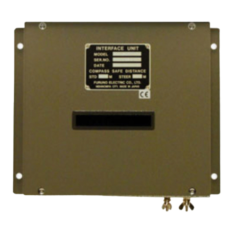
Furuno CU-300 User manual

MEMORY CARD INTERFACE UNIT
CU-300
www.furuno.co.jp


i
WARNING
Indicates a potentially hazardous situation which, if not avoided,
could result in death or serious injury.
CAUTION
Indicates a potentially hazardous situation which, if not avoided,
may result in minor or moderate injury.
Warning, Caution Mandatory Action
Prohibitive Action
SAFETY INSTRUCTIONS
The user and installer must read the appropriate safety instructions before attempting to install
or operate the equipment.
WARNING WARNING
Do not disassemble or modify the
equipment.
Fire, electrical shock or serious injury can
result.
Do not place liquid-filled containers on
the top of the equipment.
Fire or electrical shock can result if a liquid
spills into the equipment.
Make sure no rain or water splash leaks
into the equipment.
Fire or electrical shock can result if water
leaks in the equipment.
Do not operate the equipment with
wet hands.
Electrical shock can result.
Do not open the equipment.
Only qualified personnel should work
inside the equipment.
Immediately turn off the power at the
switchboard if water leaks into the
equipment or something is dropped
into the equipment.
Continued use of the equipment can cause
fire or electrical shock. Contact a FURUNO
agent for service.
Immediately turn off the power at the
switchboard if the equipment is emitting
smoke or fire.
Continued use of the equipment can cause
fire or electrical shock. Contact a FURUNO
agent for service.
Turn off the power immediately
if you feel the equipment is behaving
abnormally.
Turn off the power at the switchboard if
the equipment becomes abnormally warm
or is emitting odd noises. Contact a
FURUNO dealer or agent for advice.
Safety instructions for the operator
ii
WARNING
Turn off the power at the
switchboard before beginning the
installation.
Fire or electrical shock can result if
the power is left on.
CAUTION
Observe the following compass safe
distances to prevent interference to a
magnetic compass:
Attach grounding securely
to ship's body.
The grounding is required
to prevent electrical shock.
Standard
compass Steering
CU-300
compass
0.45 m0.70 m

iii
TABLE OF CONTENTS
SYSTEM CONFIGURATIONS....................................................................iv
EQUIPMENT LISTS....................................................................................vi
1. MOUNTING............................................................................................1
1.1 Flush Mounting.............................................................................................................1
1.2 Desktop Mounting.........................................................................................................2
1.3 Overhead Mounting......................................................................................................3
2. WIRING..................................................................................................5
2.1 Connection between One Processor Unit and One Memory Card Interface Unit ........5
2.2 Connection between One Memory Card Interface Unit and Multiple Processor Units
(Max. Three Units)........................................................................................................6
2.3 Connection between Two Memory Card Interface Units and Two Processor Units.....7
3. OPERATION..........................................................................................9
3.1 Basic Operation............................................................................................................9
3.2 Priority of Card Drives ................................................................................................10
SPECIFICATION....................................................................................SP-1
PACKING LISTS......................................................................................A-1
OUTLINE DRAWINGS.............................................................................D-1

iv
SYSTEM CONFIGURATIONS
The Memory Card Interface Unit CU-300 connects to a processor unit of MODEL18x4C-BB/
19x4C-BB or GD-1920C-BB (NavNet VX2-BB) to provide a card drive(s) in a remote location(s).
Power to the CU-300 is supplied from the processor unit. Maximum four units can be connected
via a HUB. Note that the CU-300 can be connected only to the NavNet VX2 units which have the
following software version No.
C-MAP specification
Type Version No.
MODEL 18x4C-BB/19x4C-BB, GD-1920C-BB 1950026-02.01 and after
MODEL 18x4C/19x4C, GD-1920C 1950024-02.01 and after
MODEL 17x4C, GD-1720C 1950028-02.01 and after
NAVIONICS specification
Type Version No.
MODEL 18x4C-BB/19x4C-BB, GD-1920C-BB 1950025-01.09 and after
MODEL 18x4C/19x4C, GD-1920C 1950023-01.09 and after
MODEL 17x4C, GD-1720C 1950027-01.09 and after

v
Connection to single NavNet VX2-BB unit
Connection to multiple NavNet VX2-BB units
Power cable
MJ-A3SPF0026-050C or 100C
Ethernet cable
MJ-A6SPF0017-050C or 100C
CU-300
Model 18x4C-BB/19x4C-BB
GD-1920C-BB
Power cable
MJ-A3SPF0026-050C or 100C
CU-300
Model 18x4C-BB/19x4C-BB
GD-1920C-BB
HUB
Model 18x4C-BB/19x4C-BB, GD-1920C-BB,
Model 18x4C/19x4C, GD-1920C
Model 17x4C or GD-1720C
LAN cable (CAT5,
STP, straight)
: Standard supply
: Local supply
: NavNet VX2
: Option for NavNet VX2
Model 18x4C-BB/19x4C-BB, GD-1920C-BB,
Model 18x4C/19x4C, GD-1920C
Model 17x4C or GD-1720C

vi
Connection for two CU-300
Power cable
MJ-A3SPF0026-050C
or 100C
CU-300
HUB
LAN cable (CAT5,
STP, straight)
: Standard supply
: Local supply
: NavNet VX2
: Option for NavNet VX2
Model 18x4C-BB/19x4C-BB
GD-1920C-BB
CU-300
Model 18x4C-BB/19x4C-BB
GD-1920C-BB

vii
EQUIPMENT LISTS
Standard supply
Optional supply
Name Type Code No. Qty Remarks
Memory Card Interface
Unit CU-300 - 1
Installation Materials
(Select one.) CP03-27400 000-081-570 1 set For 5 m, MJ-A6SPF0017-050C,
MJ-A3SPF0026-050C, and
CP03-27401
CP03-27410 000-081-571 1 set For 10 m, MJ-A6SPF0017-
100C, MJ-A3SPF0026-100C,
and CP03-27401
CP03-27440 000-083-403 1 set For 5 m, MJ-A3SPF0026-050C
and CP03-27401
CP03-27450 000-010-245 1 set For 10 m, MJ-A3SPF0026-100C
and CP03-27401
Name Type Code No. Qty Remarks
Hanger FP03-10201 008-539-530 1 set For desktop mounting
Console Mounting
Kit FP03-10203 001-011-710 1 set For bulkhead mounitng
Cable Assy MJ-A3SPF0026-050C 000-157-944-10 1 5 m, power cable
MJ-A3SPF0026-100C 000-157-945-10 1 10 m, power cable
MJ-A6SPF0017-050C 000-159-705-11 1 5 m, Ethernet cable
MJ-A6SPF0017-100C 000-159-706-11 1 10 m, Ethernet cable

1
1. MOUNTING
The memory card interface unit can be flush mounted in a console, or mountd on a desktop or the
overhead.
Choose a mounting location for the unit considering the following points:
• Leave sufficient space around the unit to facilitate checking and maintenance. See outline
drawing at the back of this manual for recommended maintenance space.
• Locate the unit well away from exhaust gases and other active gases.
• The location should be well ventilated.
• Choose a location where shock and vibration are minimal.
• Only the front panel is waterproofed.
Note: For flush mount or bulkhead mount, the DIP switch setting should be completed before
mounting. See page 8.
1.1 Flush Mounting
1. Prepare a cutout in the mounting location as below.
2. Screw four threaded rod (M4×50, supplied) into holes on the front panel (reverse side).
3. Insert the unit into the cutout made at step 1.
4. Fix the unit with four spring, flat washers, and hex. nuts.
150.5+0.5
143+1
4.5
R2.25
54+1
24+0.5
Screw threaded rods into
these holes.
Rear view Threade
d
rod

2
1.2 Desktop Mounting
This method requires the optional hanger FP03-10201.
Name: Hanger (Type: FP03-10201, Code no.: 008-539-530)
1. Fasten four pan head screws (M4×10) to fix the hanger to the unit.
2. Fix the hanger with unit to the mounting location with four self-tapping screws (φ5×20).
Contents of kit FP03-10201
Name Type Code No. Qty
Hanger 19-023-3081 100-316-250 1
Self-tapping screw φ5×20, SUS304 000-162-608-10 4
Pan head screw M4×10, C2700W 000-163-167-10 4
198 #100
145
20
42
171
60
98
Spring washer, flat washer and hex. nut

3
1.3 Overhead Mounting
This method requires the optional kit FP03-10203.
Name: Console mounting kit (Type: FP03-10203, Code no.: 001-011-710)
Contents of kit FP03-10203
Name Type Code No. Qty
Mounting plate 19-023-3091 100-316-260 1
Pan head screw M4×10 C2700W 000-163-167-10 4
Hex. nut M4 SUS304 000-863-106 4
Flat washer M4 SUS304 000-864-126 4
Spring washer M4 SUS304 000-864-256 4
#100
6 Fixing hole
198
163+0.5
41.5
2.2
171
179
#20 #20
62
42 198
100+0.5

4
1. Prepare four fixing holes in the bulkhead whose dimensions are as shown below.
2. Fasten four pan head screws (M4) to fix the mounting plate to the unit.
3. Insert four studs at the top of the mounting plate in fixing holes made at step 1, and then pass
spring washers, flat washers and hex. nuts onto in that order from inside the bulkhead.
4. Tighten hex nuts to fix the unit.
Dimensions for overhead mounting
5
120+0.5
120+0.5
120+0.5
120+0.5
77
31.5
2.2
42 198 Nut (M4)
#100
Max. 8
14
63
102
171 #20
#20

5
2. WIRING
There are three types of connections:
• Connection between one processor unit and memory card interface unit.
• Connection between one memory card interface unit and multiple processor units
• Connection between two memory card interface units and two processor units.
Note that the total number of card slots is maximum four in a series.
2.1 Connection between One Processor Unit and
One Memory Card Interface Unit
POWER
DATA 3
NETWORK
CONT DATA 1
DATA 2
DJ-1
REMOTE FMD DISPLAY
RGB OUT
NTSC/PAL
2
GND
3
INPUT
12-24 VDC
1
CARD SLOT
3
2
1
GND
F.G.
12 VDC
OUTPUT
OPTION
0.3 A MAX
Ground
Ground wire
IV-1.25sq
(Local supply)
Power cable
MJ-A3SPF0026-050C or 100C
Ethernet cable
MJ-A6SPF0017-050C or 100C

6
2.2 Connection between One Memory Card Interface
Unit and Multiple Processor Units (Max. Three
Units)
Prepare the following cables and connectors:
• Commercial LAN cable (CAT5, STC, straight)
• Cable assy, MJ-A6SPF0014-010C/050C/100C/200C/300C (option for NavNet VX2)
• Converter connector, MJA6SERMD/TM11AP8-005 (option for NavNet VX2)
POWER
DATA 3
NETWORK
CONT DATA 1
DATA 2
DJ-1
REMOTE FMD DISPLAY
RGB OUT
NTSC/PAL
2
GND
3
INPUT
12-24 VDC
1
CARD SLOT
3
2
1
GND
F.G.
12 VDC
OUTPUT
OPTION
0.3 A MAX
Ground
Ground wire
IV-1.25sq
(Local supply)
Power cable
MJ-A3SPF0026-050C or 100C
HUB
LAN cable
(CAT5, STP, straight,
local supply)
NavNet VX2 or
NavNet VX2-BB
Processor unit
NavNet VX2 or
NavNet VX2-BB
Processor unit
NavNet VX2-BB
Processor unit
Cable assy
MJ-A6SPF0014-010C/
050C/100C/200C/300C
(Option for NavNet VX2)
Converter connector
MJA6SRMD/TM11AP8-005
(Option for NavNet VX2)

7
2.3 Connection between Two Memory Card
Interface Units and Two Processor Units
Prepare the following cables and connectors:
• Commercial LAN cable (CAT5, STP, straight)
• Cable assy, MJ-A6SPF0014-010C/050C/100C/200C/300C (option for NavNet VX2)
• Converter connector, MJA6SERMD/TM11AP8-005 (option for NavNet VX2)
POWER
DATA 3
NETWORK
CONT DATA 1
DATA 2
DJ-1
REMOTE FMD DISPLAY
RGB OUT
NTSC/PAL
2
GND
3
INPUT
12-24 VDC
1
CARD SLOT
3
2
1
GND
F.G.
12 VDC
OUTPUT
OPTION
0.3 A MAX
Ground
Ground wire
IV-1.25sq
(Local supply)
Power cable
MJ-A3SPF0026-050C or 100C
HUB
LAN cable
(CAT5, STP, straight,
local supply)
NavNet VX2-BB
Processor unit
Cable assy
MJ-A6SPF0014-010C/
050C/100C/200C/300C
(Option for NavNet VX2)
Converter connector
MJA6SRMD/TM11AP8-005
(Option for NavNet VX2)
POWER
DATA 3
NETWORK
CONT DATA 1
DATA 2
DJ-1
REMOTE FMD DISPLAY
RGB OUT
NTSC/PAL
2
GND
3
INPUT
12-24 VDC
1
CARD SLOT
3
2
GND
F.G.
12 VDC
OUTPUT
OPTION
0.3 A MAX
Ground
Ground wire
IV-1.25sq
(Local supply)
Power cable
MJ-A3SPF0026-050C or 100C
NavNet VX2-BB
Processor unit LAN cable
(CAT5, local supply)
Converter connector
MJA6SRMD/TM11AP8-005
(Option for NavNet VX2)

8
Setting of the IP address for the second memory card interface unit
When connecting two memory card interface units, change the DIP switch setting on the second
unit as below to change its IP address. Note that the second unit is exclusively for reading chart
card.
1. Unfasten two pan head screws (M3x8), a wing bolt and a washer for MJ connector at the rear
of the unit.
2. Unfasten four screws and the connector at the location shown below to remove the front
panel.
3. Unfasten four pan head screws at the inner front chassis to remove it.
4. Pull out the inner chassis to it.
5. Set the #4 segment of DIP switch S1 as below.
PCB 19P1050
6. Re-assemble the unit.
S1
4 3 2 1
ON
OFF

9
3. OPERATION
3.1 Basic Operation
Card drive
Insert the appropriate chart SD card (or memory card) for your area as below. For details of SD
cards, see the operator’s manual for NavNet VX-2.
1. Open the card drive.
2. Insert the card (label side up) prior to turning on the power at NavNet VX2-BB.
3. Close the lid.
To remove the card, follow the instructions shown on the display of NavNet VX2 and then confirm
that the power lamp on the front panel lights. Do not read/write the data.
Power lamp
Lights (green): The power is on.
Blinks: The unit is reading/writing data.
Card box
You can store two SD cards here.
Note 1: When the connection between NavNet VX2-BB and memory card interface unit is wrong,
the NavNet VX2-BB searches for chart data in the SD card for 50 seconds, and then returns to
the normal operation. The display looks frozen, however normal operation will be restarted after
the search is completed.
Note 2: To prevent loss of card dataif thepower suddenly goes off,it is recommended that
you periodically back up data to an SD card.
Power lamp
(green)
Card drive
Card box
(Strage for two cards)

10
3.2 Priority of Card Drives
The priority of card drives is automatically setafter turning the power on.This priority ordervaries
depending on the number of card drives connected.
One memory card interface unit
Unit and available chart card and memory card locations
The numbers in the table refer to the corresponding units in the figure above.
Unit Available chart card
locations Available memory card
location
112342
3NavNet VX2 12343
NavNet VX2-BB 12342
4NavNet VX2 12344
NavNet VX2-BB 12342
HUB
NavNet VX2 or
NavNet VX2-BB
Processor unit
NavNet VX2 or
NavNet VX2-BB
Processor unit
NavNet VX2-BB
Processor unit
CU-300
1
2
3
4

11
Two memory card interface units
Unit and available chart card and memory card locations
The numbers in the table refer to the corresponding units in the figure
above.
Unit (priority) Available chart card
locations Available memory card
location
112342
312342
HUB
NavNet VX2-BB
Processor unit
CU-300
1
2
3
4
NavNet VX2-BB
Processor unit
CU-300*
*: For the second CU-300, DIP switch settin
g
is necessary.
Table of contents
Other Furuno Recording Equipment manuals

Furuno
Furuno IF-1500AIS User manual

Furuno
Furuno IF-2000 User manual

Furuno
Furuno CN-24 User manual

Furuno
Furuno IF-2550 User manual

Furuno
Furuno INTERFACE UNIT IF-2500 User manual

Furuno
Furuno Interface Unit IF-5000/5001 User manual

Furuno
Furuno IF-5200 User manual

Furuno
Furuno IF-NMEASC User manual

Furuno
Furuno IF-5200 User manual
Popular Recording Equipment manuals by other brands

Roland
Roland R-4 PRO - ANNEXE 109 supplementary guide

SMAR
SMAR PCI302 Operation, maintenance & instruction manual

M-Audio
M-Audio FireWire 410 user guide

Cochlear
Cochlear Baha 6 Max user manual

Secure Wireless
Secure Wireless EV-REC3 Evolution Series manual

WifiTrax Model Science
WifiTrax Model Science WFD-30 Getting started