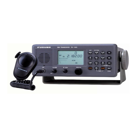
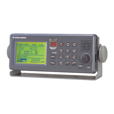
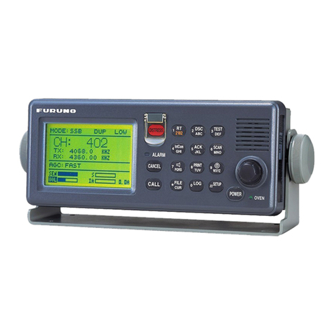
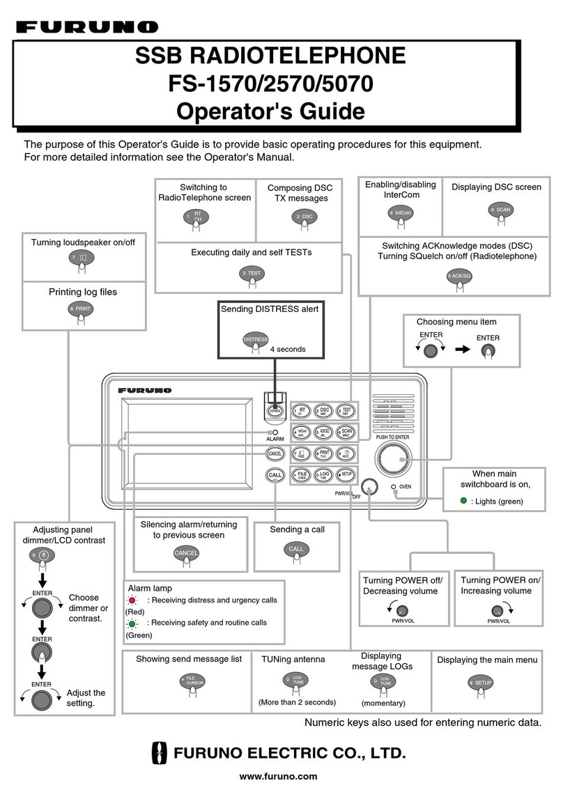
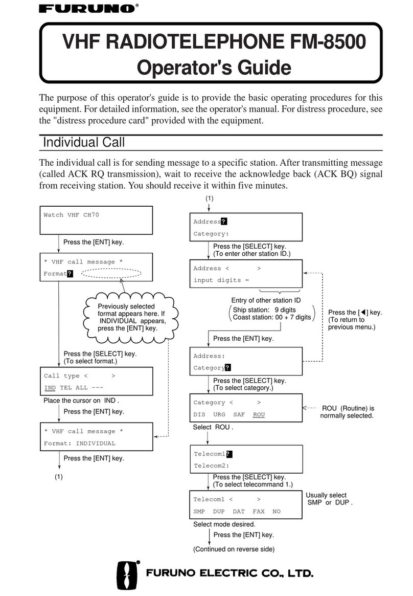
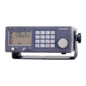
Furuno FS-1570 User manual

SSB Radio telephone
FS-1570/2570

Your Local Agent/DealerYour Local Agent/Dealer
9-52 Ashihara-cho,9-52 Ashihara-cho,
Nishinomi
y
a, Ja
p
anNishinomi
y
a, Ja
p
an
Tele
p
hone :Tele
p
hone : 0798-65-21110798-65-2111
Telefax :Telefax : 0798-65-42000798-65-4200
FIRST EDITION :FIRST EDITION : JAN.JAN. 20032003
Printed in JapanPrinted in Japan
A
ll ri
g
hts reserved.
A
ll ri
g
hts reserved.
PUB.No.PUB.No. SME-56360-ASME-56360-A
(( NAYONAYO )) FS-1570/2570FS-1570/2570
*SME56360A00**SME56360A00*
* S M E 5 6 3 6 0 A 0 0 ** S M E 5 6 3 6 0 A 0 0 *

1
Check List......................................................................................................................i
Chapter 1. General
1.1 General...........................................................................................................................1-1
1.2 Configuration of System................................................................................................1-2
1.2.1 FS-1570 (150W) .............................................................................................1-2
1.2.2 FS-2570 (250W) .............................................................................................1-3
1.3 Connection of NBDP terminal, IB-581 .........................................................................1-4
1.4 Port Specification ..........................................................................................................1-5
1.5 Handset..........................................................................................................................1-6
1.6 Communication priority ................................................................................................1-6
1.7 Display of Receiving DSC message..............................................................................1-7
1.8 Power Status Monitor, PSM-01.....................................................................................1-8
1.9 Using NBDP..................................................................................................................1-8
Chapter 2. Location of Parts
2.1 FS-2570C.......................................................................................................................2-1
2.2 FS-2570T.......................................................................................................................2-5
2.3 FS-1570T.......................................................................................................................2-9
2.4 Boards in Transceiver Unit............................................................................................2-13
2.5 Antenna coupler.............................................................................................................2-20
2.6 Terminal unit, IB-583 ....................................................................................................2-24
2.6.1 Boards in Terminal Unit ..................................................................................2-28
2.7 Handset (HS-2001)........................................................................................................2-30
Content
s

Contents
2
Chapter 3. Set up
3.1 MMSI Number, Model and Group ID...........................................................................3-1
3.1.1 MMSI Number (MMSI CLEAR)....................................................................3-1
3.1.2 Model (ALL CLEAR).....................................................................................3-2
3.1.3 Group ID .........................................................................................................3-3
3.2 RT SETUP.....................................................................................................................3-4
1. NB (ON/OFF).............................................................................................3-6
2. SQ FREQ. (500 Hz-2000 Hz).....................................................................3-6
3. FAX RX ENABLE (ON/OFF) ...................................................................3-6
4. USER CH (USER CH ENTRY).................................................................3-6
5. OFFHOOK SPKER (ON/OFF)..................................................................3-7
6. REGULATION (INTL): Reserved for future use.......................................3-7
7. TX FREQ. (FREE, MARINE/USER, ITU/USER)....................................3-8
8. RX FREQ. (FREE, MARINE/USER, ITU/USER)....................................3-8
9. USER CH (ON/OFF)..................................................................................3-9
10. AM ENABLE (ON, TRX, RX)................................................................3-9
11. LSB ENABLE (ON/OFF).........................................................................3-9
12. TX TUNE (ON/OFF) ...............................................................................3-9
13. COUPLER THROU (OFF, RCVD, DIFF)...............................................3-10
14.TONE.........................................................................................................3-10
15. TX POWER (FREQ.)...............................................................................3-10
16. TX POWER (USER CH) .........................................................................3-10
3.2.1 USER CH Registration..................................................................................3-11
3.2.2 Erasing all user channels................................................................................3-12
3.2.3 Erasing user channel individually..................................................................3-13
3.3 DSC SETUP..................................................................................................................3-14
1. ALARM......................................................................................................3-16
2. AUTO ACK ...............................................................................................3-17
3. ERASE.......................................................................................................3-18
4. MESSAGE.................................................................................................3-20
5. POSITION..................................................................................................3-23
6. PRINT OUT ...............................................................................................3-24
7. SCAN FREQ..............................................................................................3-25
8. VOLUME...................................................................................................3-25
9. TEST ..........................................................................................................3-26
10. SYSTEM..................................................................................................3-27
3.4 DIP Switch.....................................................................................................................3-29
1. Receiving Position data..............................................................................3-30
2. Connecting Distress Alert Button...............................................................3-31
3. Connecting Incoming Indicator..................................................................3-32
4. Connecting PC............................................................................................3-33

Contents
3
3.5 Jumper ...........................................................................................................................3-34
3.5.1 When FAX-5 is used for W/R ........................................................................3-34
3.5.2 When TR antenna is used for W/R.................................................................3-35
3.6 Installing DSP board for NBDP ....................................................................................3-36
3.7 IB-581/IB-583................................................................................................................3-37
3.7.1 Manual Reception menu (F3, 6).....................................................................3-38
3.7.2 Station menu (F5)...........................................................................................3-38
1. Registering Answerback.............................................................................3-39
2. Registering ID number ...............................................................................3-40
3.7.3 System menu (F6)...........................................................................................3-41
3.7.4 Printer and language setting............................................................................3-43
Chapter 4. Updating program
4.1 General...........................................................................................................................4-1
4.2 Connection.....................................................................................................................4-2
4.2.1 C-CPU.............................................................................................................4-2
4.2.2 T-CPU, DSC MODEM and NBDP MODEM................................................4-2
4.2.3 IB-583 .............................................................................................................4-3
4.3 DIP Switch Setting ........................................................................................................4-3
4.4 Updating Program..........................................................................................................4-4
4.4.1 T-CPU and C-CPU.........................................................................................4-4
4.4.2 DSC MODEM and NBDP MODEM .............................................................4-7
4.4.3 IB-581.............................................................................................................4-9
4.4.4 IB-583.............................................................................................................4-11
4.5 Contents of Program File...............................................................................................4-13
1. C-CPU (FS-2570C) Program number; 0550206-01.xx...............................4-13
2. T-CPU (FS-1570T/FS-2570T) Program number; 0550205-01.xx..............4-13
3. DSC MODEM (DSC DSP board) Program number; 0550207-01.xx.........4-14
4. NBDP MODEM (NBDP DSP board) Program number; 0550208-01.xx...4-14
5. IB-583 (FS-1570/FS-2570 NBDP terminal) Program number;
0550209-22.xx.............................................................................................4-14
6. IB-581 (FS-1570/FS-2570 NBDP terminal) Program number;
0550210-22.xx.............................................................................................4-15

Contents
4
Chapter 5. Block Description
5.1 Configuration.................................................................................................................5-1
5.1.1 Transceiver unit ..............................................................................................5-1
5.1.2 Boards in Transceiver unit..............................................................................5-3
5.1.3 Control unit, FS-2570C...................................................................................5-5
5.1.4 NBDP Terminal unit: IB-581/583 (Option)....................................................5-6
5.1.5 Antenna coupler unit.......................................................................................5-8
5.2 Power supply unit..........................................................................................................5-9
5.2.1 General............................................................................................................5-9
5.2.2 RELAY board (05P0744)................................................................................5-10
5.2.3 SW REG board (05P0737) .............................................................................5-10
5.3 T-CPU board (05P0732)................................................................................................5-11
5.3.1 Function of CPU.............................................................................................5-12
5.3.2 Memory...........................................................................................................5-12
5.3.3 Control signals................................................................................................5-13
5.3.4 Interface circuit ...............................................................................................5-19
5.3.5 Digital Signal Processor (DSP).......................................................................5-21
5.4 TX/RX Board (05P0733)...............................................................................................5-22
5.4.1 Block diagram.................................................................................................5-22
5.4.2 Local oscillator................................................................................................5-23
5.4.3 Transmitter/Receiver circuit............................................................................5-25
5.5 Power Amplifier (PA)....................................................................................................5-32
5.5.1 FS-1570T PA board (05P0735).......................................................................5-32
5.5.2 FS-2570T DRV board (05P0738)...................................................................5-34
5.5.3 FS-2570T PA board (05P0739).......................................................................5-35
5.5.4 FS-2570T COMB board (05P0740)................................................................5-36
5.5.5 TX FIL board (05P0736) ................................................................................5-37
5.6 W/R board (05P0734)....................................................................................................5-39
5.7 C-CPU Board (05P0729)/C-IF Board (05P0730)..........................................................5-42
5.7.1 C-CPU Board (05P0729)................................................................................5-43
1. CPU.............................................................................................................5-43
2. Memory.......................................................................................................5-43
3. LED .............................................................................................................5-43
4. NMI SW......................................................................................................5-43
5.7.2 C-IF Board (05P0730) ....................................................................................5-44
5.7.3 Handset ...........................................................................................................5-45

Contents
5
5.8 Antenna coupler, AT-1560.............................................................................................5-46
5.8.1 Antenna tuning................................................................................................5-52
5.9 IB-583............................................................................................................................5-57
5.9.1 TERM CPU board (16P0209A)......................................................................5-58
5.9.2 PWR Board (16P0211A) ................................................................................5-59
Chapter 6. Maintenance
6.1 Self-test..........................................................................................................................6-1
6.1.1 DSC test..........................................................................................................6-1
6.1.2 RT test.............................................................................................................6-5
6.2 Self test of Antenna coupler ..........................................................................................6-10
6.3 Self-test of Terminal Unit..............................................................................................6-11
6.4 Tone test.........................................................................................................................6-13
6.5 TEST function in DSC SETUP menu...........................................................................6-15
6.5.1 Unlocking TEST menu...................................................................................6-15
6.6 Messages........................................................................................................................6-21
6.6.1 Message on control unit..................................................................................6-21
6.6.2 Message on NBDP terminal............................................................................6-24
6.7 Changing Back-up battery on IB-583: TERM CPU board............................................6-26
Chapter 7. Adjustment and Measurement
7.1 Output power.................................................................................................................7-1
7.1.1 Power Data......................................................................................................7-1
7.1.2 Output power measurement............................................................................7-3
7.1.3 Adjustment of output power for operating frequency ...................................7-4
7.1.4 Adjustment of output power for user channel.................................................7-6
7.2 Frequency ......................................................................................................................7-8
7.2.1 Measurement of TX operating frequency.......................................................7-8
7.2.2 Tone frequency................................................................................................7-10
7.3 PA Bias ..........................................................................................................................7-13
7.4 TX Gain.........................................................................................................................7-17
7.5 RX Gain.........................................................................................................................7-18

Contents
6
Appendix 1) DSC Frequency List...............................................................................AP1-1
Appendix 2) DSC and NBDP Test Calls....................................................................AP2-1
AP2.1 DSC Test Call ...............................................................................................AP2-1
AP2.2 NBDP test.....................................................................................................AP2-3
AP2.2.1 Receiving MSI (Maritime safety Information) ......................................AP2-3
AP2.2.2 ARQ communication.............................................................................AP2-5
Appendix 3) Cancelling and receiving distress alert............................................AP3-1
AP3.1 Cancelling distress alert................................................................................AP3-1
AP3.2.......................................................................................................................AP3-1
Appendix 4) Specifications..........................................................................................AP4-1
Appendix 5) Factory acceptance test sheet............................................................AP5-1
Exploded View.................................................................................................................D-1
Electrical Parts List........................................................................................................E-1
Contents of Drawings....................................................................................................S-0
Schematic Diagrams......................................................................................................S-1

i
1. Check of installation
The cable must be fixed firmly and tidy.
No. Item to be checked Result Refer to
1.1 Do you understand the system configuration? Chapter 1
1.2
Mounting and wiring of transceiver, controller and power
supply unit
- All securing screws are fully tightened.
- Units are grounded.
- All connections are made correctly.
- All connecting wires are secured.
1.3
MF/HF TX/RX antenna
- The lead-in wire is secured without slack.
- The antenna does not touch to other objects such as mast,
derrick post and rigging.
- For safety, “WARNING: High voltage” sign and suitable guards
are provided to prevent personnel from coming in accidental
contact with dangerous voltage on the lead-in wire.
- The lead-in insulator is clean.
1.4
Antenna coupler AT-1560
- The grounding is connected securely.
- The antenna wire is secured.
- The shield of the coaxial cable and the control signal cable are
fabricated correctly and grounded.
- Wires and parts in the matching circuit are not touched each
other.
1.5 RX antenna (FAX-5)
- Check for grounding.
- Check for waterproofing.
1.6 NBDP terminal
When NBDP terminal is connected, optional NBDP DSP board is
installed. Page 3-36
1.7 W/R2 board for FS-2570
All connections are made on W/R2 board, if provided. When T/R
antenna is used, JP1 and JP2 on TX FIL board are changed. Page 3-34
Page 3-35
1.8 ID, CS, AAB display
MMSI, CS, AAIC, AAB and ID are marked on the controller unit,
the terminal unit or nearby those units with labels.
1.9 Power supply unit
Check the power supply unit for power specification. Power
alteration includes the change of internal wiring and fuse.
Check List

Check List
ii
2. Check of settings
No. Item to be checked Result Refer to
2.1 JP-3 on W/R board (power to the antenna unit, Default: OFF) Page 3-34
2.2 DIP switch setting on T-CPU board for the connection of GNSS,
incoming indicator and distress alert button. Page 3-29
2.3 Check registered MMSI in DSC Setup display. Page 3-1
Page 3-27
2.4 Model, FS-1570 or FS-2570 is selected through the menu. Power
data and contents of RT self test differ between two models. Page 3-2
2.5 The RT is set through Setup menu.
TX FREQ is set in accordance with local regulation. Page 3-4
Page 3-8
2.6 “SYSTEM” setting of DSC Setup menu is made.
WATCH RCVR is set to HF for the ship navigating in the sea area
A3. Page 3-14
Page 3-25
2.7 NBDP terminal is setup through the menu, and AAB and ID are
registered. “Slave Delay” of System ([F6]) menu is set to 8 msec. Page 3-37
MMSI and model registration
1. Press NMI SW (S1) on T-CPU board and enter the password.
2. Select “ALL Clear” and the press [ENT].
JP-3 setting on W/R-1 and 2 boards
Jumper Remarks
1-2 12 V to FAX-5
JP-3 2-3 No power to antenna (Factory setting)

Check List
iii
DIP switch setting on T-CPU board The default setting is screened.
SW Function #1 #2 #3 #4
C. Loop OFF
(IEC: Pos.) OFF
(DMC) OFF
(MIF) OFF
(N.C)S2
RS-422 ON ON ON
RS-232C OFF OFF ON ON
S3 RS-422 ON ON OFF OFF
S4 ON ON ON ON
IC-303-DSC S5 OFF OFF OFF OFF
S4 OFF OFF OFF OFF
S4, S5
IC-xxx S5 ON ON ON ON
S6 ON ON ON ON
DMC-5 S7 OFF OFF OFF OFF
S6 OFF OFF OFF OFF
S6, S7
IC-302-DSC S7 ON ON ON ON
DSC System setup menu The default setting is screened.
Items to be set Value
RCVD CALL ON OFFINTERNAL
AUDIO
ALARM OLD
POSITION ON OFF
POSITION OLDER 4.0, 3.0, 2.0, 1.0, 0.5H
ALARM
EXT ALARM DIS/URG ROUTINE ALL OFF
COMPLY TYPE UNABLE ABLE
UNABLE REASON NO REASONGIVEN
POSITION CALL ON OFF
AUTO ACK
POLLING CALL ON OFF
POSITION INPUT TYPE AUTO MANUAL
XMIT CALL AUTO MANUAL
RCVD CALL AUTO MANUAL
PRINT OUT
DAILY TEST AUTO MANUAL
ROUTIINE F1-F6: OFF
SCAN FREQ. DISTRESS 2, 8M: FIXED 4, 6, 12, 16M: ON
KEY CLICK ON OFF
HANDSET 32 (0-63)
ORDINARY ALARM 35 (0-63)
VOLUME
DISTRESS ALARM 38 (38-63)
MMSI FIXED
LINE OUT +0.0 DB (-4.5 to +4.5dB in1.5dB step)
WATCH RCVR MF/HF MF
CH DET S LEVEL 100 (OFF – 255)
SYSTEM
(PASSWORD)
REGULATION INTL RUSSIA

Check List
iv
RT System setup menu
The default setting is screened.
Menu Setting
NB OFF ON
SQ FREQ 500Hz to 2000Hz (800Hz)
FAX RX ENABLE OFF ON
OFFHOOKED SPKER OFF ON
SYSTEM Password is needed to set following items.
REGULATION INTL
TX FREQ FREE MARINE ITU/USER USER
RX FREQ FREE MARINE ITU/USER USER
USER CH OFF ON
AM ENABLE OFF TRX RX
LSB ENABLE OFF ON
TX TUNE OFF ON
COUPLER THROU OFF RCVD DIFF
NBDP terminal setup menus, IB-581and IB-583
The default setting is screened.
Items Value Remarks
F3: Operate 6.Manual Reception AUTO, ARQ, FEC,
DIRCT
5.Answerback Code Entry MMSI+CS(4digit)+X Password:
ANSWER CODE
6.Group ID Entry (4/5 digit)
7.Group ID Entry (9 digit)
8.Select ID Entry (4/5 digit) Sell call number
F5: Station
9.Select ID Entry (9 digit) MMSI
Password:
ID CODE
Slave Delay 8msec (0-50msec) Password: DP6
TX/RX MSG Save ON, OFF
Edit before sending ON, OFF
Time System OFF, UTC, SMT,
JST
Time & Date
** Display Mode Normal, Reverse Only IB-581 appears
F6: System
** Window color Window color setup
Default Only IB-583 appears
Language Normal, Norway,
Sweden, UK
Fn+F1
Printer PP-510, OTHER
Password: DP6
Note: Enter the password in capital letter.

Check List
v
3. Self test
No. Test Procedure Result Refer to
3.1 DSC self test Press [3 TEST] with DSC display. Page 6-1
3.2 RT self test
Press [3 TEST] with RT display. Items to be
checked differ between FS-1570 and
FS-2570. Page 6-5
3.3 Terminal unit self
test [F6], select “self test”Page 6-11
3.4 Antenna coupler
self test
Set S2#2 to ON and press [S3:TUNE] on the
COUP board.
The self test is not executed when
[S1:MANUAL/AUTO] is set to MANUAL.
Page 6-10
3.5 Printer self test
To print out the self test result, turn on the
system while holding down [LF].
To print out the DIP switch setting, turn on the
system while holding down [NLQ].
4. Check of program version
Use the system with the latest program.
No. How to read program number Refer to
4.1 Press [3 TEST] with DSC display for DSC self test.
To check the detail program version, press [1 RT] five times while holding
down [File] with the test result display.
Page 6-1
Page 6-2
4.2 Press [F6] and select “self test”for terminal unit self test.
To check the detail program version, press [F1] while holding down [Alt]
and [Fn] with the test result display.
Page 6-11
4.3 U1 in antenna coupler unit Page 2-22

Check List
vi
Test result
Program Program Version
MAIN (T-CPU)
DSC modem
Transceiver unit
NBDP modem
No.1 FS-2570C: PANEL-1 (C-CPU)
Controller unit No.1 FS-2570C: PANEL-2 (C-CPU)
IB-581 Terminal unit
NBDP terminal IB-583 Terminal unit
AT-1570 U1
5. Functional check
No. Item to be checked Result Refer to
5.1 Position from GNSS is displayed in DSC display.
“POSITION”in DSC Setup menu is set to “AUTO”.
Receivable sentences are GGA, GLL, RMC and ZDA. Page 3-30
Page 3-23
5.2 TUNE OK appears in all bands.
[S1:MANUAL/AUTO] in AT-1560 is set to “AUTO”for automatic
tuning. Page 6-22
5.3 Use the check list on the next page for rated output power. Chapter 7
5.4 When the transmitting VC voltage drops more than 10%, change
the power cable to one longer diameter, if possible.
5.5 The receiver sensitivity is checked by receiving a signal from an
appropriate station or sky noise.
5.6
Using [6 SCAN], the system scans registered Routine
frequencies. Scan frequencies are entered through “SCAN”/DSC
setup menu. Routine frequencies are international frequencies if
not specified.
Page 3-25
Page 3-27
AP-1
5.7 DSC message is printed out by pressing [6 Print].
5.8
NBDP terminal
- The message is written and read to/from the floppy disk by
using “Open”and “Close”in [F1] menu.
- The file is printed out by using “File to Print”in [F1] menu.
5.9 BK circuit works normally.

Check List
vii
Transmitter check list
Meter indication
Frequency T/R
Output
(W) IC VC IA
Power
data TUNE
OK/NG Freq. Error
(within +10Hz)
J3E:
2M J2B:
J3E:
3M J2B:
J3E:
4M J2B:
J3E:
6M J2B:
J3E:
8M J2B:
J3E:
12M J2B:
J3E:
16M J2B:
J3E:
18M J2B:
J3E:
22M J2B:
J3E:
25M J2B:
6. Communication test
See Appendix 2.
Type Result
Called
station Frequency Time
Telephone
DSC TEST
CALL
NBDP

Check List
viii
7. Noise and interference check list
Following checks are made in all bands to make sure that no interference to and from
the radiotelephone is observed.
During transmission (voice and TLX), check that; Result
The distress alert and the incoming indicator are not interfered.
*LED brightness does not change and the buzzer sounds without noise.
*The unit is not activated.
The brightness of emergency and ordinary lights is not changed.
The head of printer does not move.
The Inmarsat B is not interfered.
*The antenna does not move.
*No change is observed in the status display.
*No noise is heard from TELs, Handset and FAX.
No noise is heard from on VHF.
No change is observed in the radar display.
No noise is heard from public addressor.
No interference to speed log, depth sounder, steering gear, navigational aids and
etc.
*Check for normal indication and functions.
No interference to the display and the indicator in the navigational panel and etc.
* Check for normal indication and functions.
The TX signal is not heard from own handset speaker of the radiotelephone.
During reception, check that; Result
No noise is heard from the radiotelephone during the charge of the battery.
No noise is heard from the radiotelephone during the reception of NMEA data.
During VHF transmission, no noise is heard from the radiotelephone.
During radar transmission, no noise is heard from the radiotelephone.

Check List
ix
Interference from FS-1570/2570
Band
2M 3M 4M 6M 8M 12M 16M 18M 22M 25M
InmarsatB
InmarsatC
No.1VHF
No.2VHF
AIS
No.1 radar
No.2 radar
No.1GPS
No.2GPS
FAX
NAVTEX
Amplifier
Sounder
VDR
Gyro
Steering
panel

1-1
1.1 General
FS-1570 (150W) and FS-2570 (250W) are a MF/HF radiotelephone with built-in DSC,
DSC watch receiver and NBDP.
1) Two controllers, FS-2570Cx2 can be connected to the transceiver unit:
[CONTROLLER-1] (high priority) and [CONTROLLER-2] ports. The system is
turned on and off only by the controller 1. The power switch on the controller 2 is
used to turn on and off the controller 2.
2) The printer for DSC and NBDP terminal (IB-583) is connected to the controller 1.
3) The DSC general frequencies watch receiver board is installed optionally into
FS-2570, but not into FS-1570. If the DSC general frequencies watch receiver
board is not used, the radiotelephone receives the DSC signal.
4) Use either “HANDSET” port. Do not use both handset ports at the same time. The
handset should be specified one.
Table1.1.1 Configuration
Unit FS-1570 FS-2570 Remarks
Transceiver unit FS-1570T
(150Wpep) FS-2570T(250Wpep)
Control unit (controller) FS-2570C A maximum of
two units
Antenna coupler AT-1560-15 AT-1560-25
Power supply unit PR-300 PR-850A
DSC general frequencies watch
receiver board - Option
Pre-amplifier for DSC W/R receiver FAX-5 (Whip ANT:2.6 m) Option
NBDP terminal IB-581 or IB-583 Option
NBDP modem board (DSP) 05P0751 Option
DMC unit DMC-5
Distress alarm button IC-302-DSC
Option
(Selecting either
one)
Incoming indicator IC-303-DSC Option
External loudspeaker SEM-21Q Option
HS-2001
Handset HSC-701K-20B Option
Printer PP-510 Option
Printer I/F IF-8500 Option
Power Status Monitor PSM-01 Option
BK controller BK-300 Option
* DSC distress and safety frequencies watch receiver board is standard built-in.
Chapter 1. General

1.2 Configuration of System
1-2
1.2 Configuration of System
1.2.1 FS-1570 (150W)
Fig.1.2.1 shows the configuration of FS-1570.
Fig.1.2.1 Configuration of FS-1570

1.2 Configuration of System
1-3
1.2.2 FS-2570 (250W)
Fig.1.2.2 shows the configuration of FS-2570.
Note)DSC general frequencies watch receiver antenna;
1) Install a DSC watch receiver antenna (FAX-5+2.6 m Whip), or
2) Use MF/HF antenna. When the antenna is used commonly, SSB and NBDP
cannot be used during the scanning of DSC general frequencies.
Fig.1.2.2 Configuration of FS-2570
Other manuals for FS-1570
6
This manual suits for next models
1
Table of contents
Other Furuno Telephone manuals

Furuno
Furuno FS-1570 User manual

Furuno
Furuno FM-8500 Manual

Furuno
Furuno FS-1575 User manual

Furuno
Furuno FS-1550 User manual

Furuno
Furuno FM-8000 User manual

Furuno
Furuno FM-8900S User manual

Furuno
Furuno FS-8000 User manual

Furuno
Furuno FS-2570 Manual

Furuno
Furuno FM-8500 User manual

Furuno
Furuno FS-5070 User manual

Furuno
Furuno FS-5000 Manual

Furuno
Furuno FS-1552 User manual

Furuno
Furuno FS-5075 (500 W) User manual

Furuno
Furuno FS-5000 User manual

Furuno
Furuno FM-8700 User manual

Furuno
Furuno FS-1562-15 User manual

Furuno
Furuno FM-2710 User manual

Furuno
Furuno FM-4000 User manual

Furuno
Furuno FM-2721 User manual

Furuno
Furuno FS-1570 User manual