Furuno FM-2721 User manual

MARINEVHF RADIOTELEPHONE
FM-2721

Your Local Agent/DealerYour Local Agent/Dealer
9-52 Ashihara-cho,9-52 Ashihara-cho,
Nishinomi
y
a, Ja
p
anNishinomi
y
a, Ja
p
an
Tele
p
hone :Tele
p
hone : 0798-65-21110798-65-2111
Telefax :Telefax : 0798-65-42000798-65-4200
FIRST EDITION :FIRST EDITION : MAR.MAR. 20002000
Printed in JapanPrinted in Japan
A
ll ri
g
hts reserved.
A
ll ri
g
hts reserved. E :E : FEB.FEB. 22,200222,2002
PUB.No.PUB.No. OME-56163OME-56163
*00080897300**00080897300*
*00080897300**00080897300*
(( HIMAHIMA )) FM-2721FM-2721 * 0 0 0 8 0 8 9 7 3 0 0 ** 0 0 0 8 0 8 9 7 3 0 0 *
*OME56163E00**OME56163E00*
* O M E 5 6 1 6 3 E 0 0 ** O M E 5 6 1 6 3 E 0 0 *

i
DISTRESS Call Procedure
Do the following when a life endangering situation
arises on your vessel:
1. Hook off the handset.
2. Press the [POWER] switch in the hanger to turn on
the unit if it is not already on.
3. Open the DISTRESS button lid in the hanger and
press the [DISTRESS] button about three seconds
to show the following display, then release the
button.
Distress call
in progress
DISTRESS CALL
Nature:
UNDESIGNATED
Pos: 12:34
12˚34E123˚45N
4. The equipment displays “Wait for AckAuto re-Xmit”
while waiting for acknowledgment of the distress call.
(Transmitting repeats with 3.5 to 4.5 minutes interval
until pressing [Cancel] key.
5. When you receive the distress acknowledgement
call, you are automatically connected to CH16. Hook
off the handset if it is not already off hook. Press the
PTT switch and say:
a) MAYDAY three times.
b) This is [name of your vessel].
c) MAYDAY
d) This is [name of your vessel].
e) Position
f) Nature of Distress
g) Kind of assistance needed
h) Number of crew
i) Other info such as description of your vessel
j) Over.

ii
INTL SIMP 25W
RCVD. DISTRESS
Rx 16
Lat: 45.23 N
Lon:121.88 E
Time:10:57UTC
VOL:08 SQ:03
<Hand set on hook>
INTL SIMP 25W
RCVD. DISTRESS
Rx
SCAN
VOL:08 SQ:03
16
<Hand set off hook>
Receiving Distress Alert from Other Ship
General
When the FM-2721 receives a distress alert from other vessel the LED (Red) lights and
the FM-2721 sounds the distress alarm.
1. Silence the alarm by pressing the [Cancel] key (or wait for two minutes).
2. Press the [Log] key to show the Sel. Log file menu.
3. Select Rcvd. DISTRESS, and then press the [Enter] key to view the contents of the
distress message.
4. Wait up to three minutes until the DISTACK signal from a coast station is received.
5. Open the Rcvd. DISTRESS file again.
6. Be prepared to follow the instructions of the coast station.
If you do not receive the DISTACK signal, follow the flow chart shown on the next page.
The DISTACK by voice can be transmitted by you under certain conditions. Please
carefully read and follow the flow chart to determine whether you should transmit it or not.
When receiving a distress alert, the LCD display appears as shown right.

iii
Should I transmit DIST ACK by voice or not?
Distress alert received.
Press the [Cancel] key
to silence alarm.
Read DISTRESS message.
Acknowledge
received from coast station?
(Wait 3 mins.)
Yes
Press the [Cancel] key
to silence alarm.
Successively to
check receive
message contents.
Continue watch on
CH 16 until you hear
[SEELONCE FINI],
which means complet-
ion of distress commu-
nication.
(Follow instructions of
coast station.)
Is
your vessel
near vessel in
distress?
No
No
Yes If you can assist the vessel
in distress, transmit
acknowledge by voice to
vessel in distress on CH 16.
1. Say "MAYDAY" ... Once
2. Say ID number of vessel in
distress ...3 times
3. Say "This is" ...Once
4. Say ID number of your vessel
... 3 times
5. Say "Received MAYDAY" ...Once

iv
SAFETY INSTRUCTIONS
CAUTION
For the operator
Distances at which radiation levels of
100 and 10 W/m exist are given in the table.
Distance to
100 W/m point Distance to
10 W/m point
22
2
0.12 m 0.39 m
Do not open the equipment.
Only qualified personal should work
inside the equipment.
Do not disassemble or modify the
equipment.
Fire, electrical shock or serious injury
can result.
Turn off the power immediately if
waterleaks into the equipment or the
equip-ment is emmitting smoke or
fire.
Continued use of the equipment can
cause fire or electrical shock.
Any repair work must be done by a
licensed radio technician.
Improper repair work can cause
electrical shock or fire.
CAUTION
Handle the handset carefully.
Rough handling may affect its
watertight integrity.

v
CAUTION
Observe the following compass safe
distances to prevent interference to a
magnetic compass:
Ground the equipment to
prevent electrical shock and
mutual interference.
Standard Steering
compass compass
WARNING
Turn off the power at the switchboard
before beginning the installation.
Fire or electrical shock can result if the
power is left on.
Do not install the equipment where it
may get wet from rain or water splash.
Water in the equipment can result in fire,
electrical shock or equipment damage.
ELECTRICAL SHOCK HAZARD
Do not open the equipment
unless totally familiar with
electrical circuits and
service manual.
Only qualified personnel
should work inside the
equipment.
WARNING
Be sure that the power supply is
compatible with the voltage rating of
the equipment.
Connection of an incorrect power supply
can cause fire or equipment damage. The
voltage rating of the equipment appears
on the label above the power connector.
For the installer
Transceiver
unit
Handset and
bracket
Loundspeaker
0.95 m 0.65 m
2.05 m 1.40 m
2.20 m 1.50 m

vi
Table of Contents
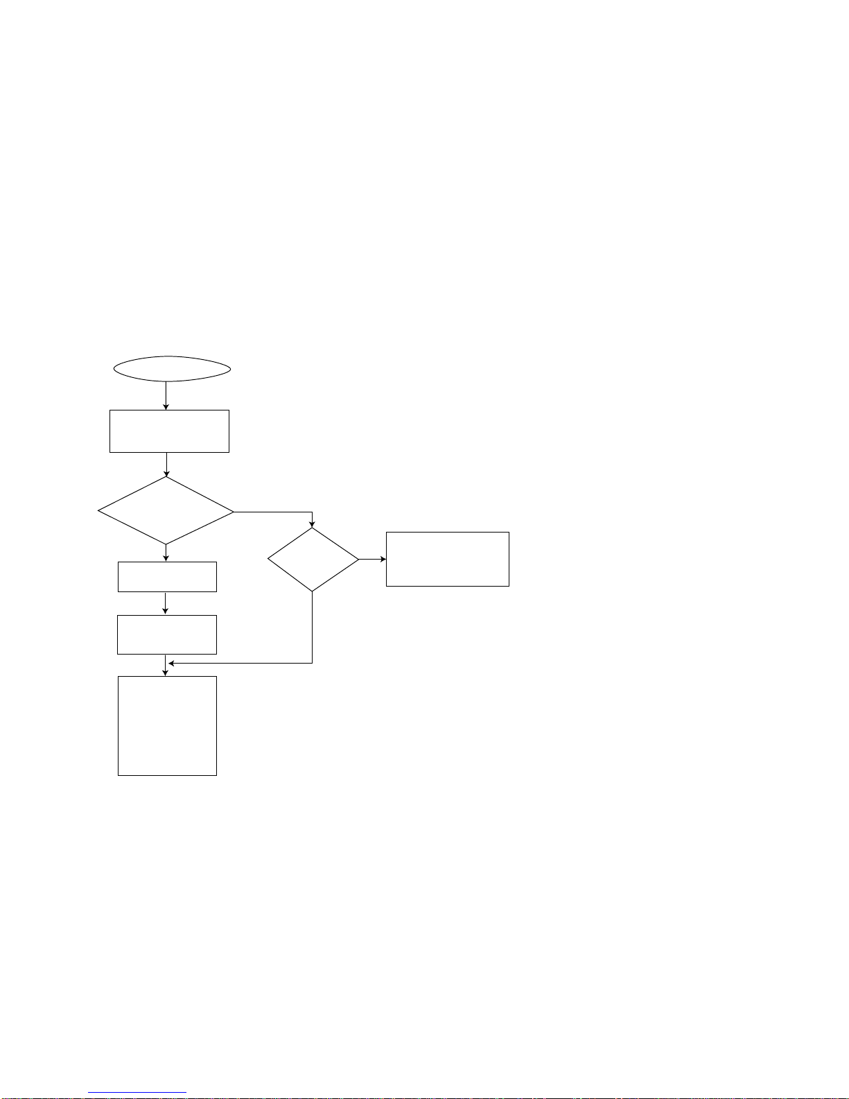
DISTRESS Call Procedure................................i
Receiving Distress Alert from Other Ship...... ii
SAFETY INSTRUCTIONS................................iv
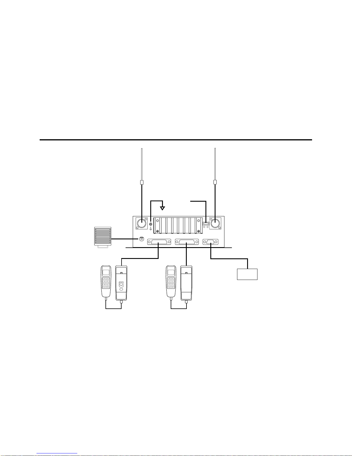
System Configuration .................................. viii
Equipment Lists.............................................. ix
Introduction..................................................... xi
1. Installation.................................................... 1
1.1 Mounting ............................................................. 1
1.2 Transceiver Connections..................................... 5
1.3 Handset Connection............................................ 9
2. Controls...................................................... 10
2.1 Controls, Indications, LEDs............................... 10
3.VHFTelephone Operation.......................... 14
3.1 Turning the Power On/Off.................................. 14
3.2 Listening for Telephony Calls ............................ 14
3.3 Adjusting the Dimmer, Contrast......................... 14
3.4 Selecting USA, INT, WX Channel...................... 15
3.5 Selecting Channel .............................................15
3.6 Adjusting Squelch..............................................15
3.7 Adjusting Loudspeaker Volume .........................16
3.8 Muting the Loudspeaker....................................16
3.9 Setting Transmitter Power.................................16
3.10 Receiving a Telephone Call.............................16
3.11 Making a Telephone Call..................................17
3.12 Dual Watch......................................................17
3.13 Starting/Stopping Scanning.............................17
3.14 Intercom ..........................................................18
3.15 Keyboard Lock ................................................18
4. DSC Operation............................................19
4.1 Distress Call......................................................19
4.2 Distress Call by [Call] key..................................20
4.3 Sending DSC Call to a Ship ..............................21
4.4 Sending DSC Call to a Coast Station................22
4.5 Sending PSTN Call to a Shore Station..............23
4.6 Sending a Group DSC Call................................25
4.7 Sending anAll Ships Call .................................26
4.8 Receiving DSC Calls.........................................27

vii
4.9 Manual Entry of Position and Time.................... 28
4.10 Storing IDs ...................................................... 29
4.11 Storing Telephone Numbers............................ 30
4.12 Storing Messages ........................................... 31
4.13 Message Log................................................... 33
5. Maintenance............................................... 35
5.1 Antenna Check.................................................. 35
5.2 Cleaning of Transceiver, Handset ..................... 35
5.3 Fuse Replacement............................................ 35
5.4 Battery Check.................................................... 35
6.Troubleshooting ......................................... 36
6.1 Easy Troubleshooting........................................ 36
6.2 Diagnostics........................................................ 38
6.3 Self check Messages........................................ 39
6.4 Menu Tree......................................................... 40
Appendix........................................................ 41
How to fabricate the cable for optional connector
17JE-23250-02/17JE-23090-02.............................. 41
VHF Channel Frequencies (Marine and Inland
waterways).............................................................. 42
VHF Weather Channel Frequencies ....................... 46
PRIVATE CHANNELS (U.K. MARINERS)............... 47
PRIVATE CHANNELS (NORDIC)............................47
PRIVATE CHANNELS (NETHERLANDS-INLAND).47
General Notes on Operating MarineVHF......48
Rules and Manners.................................................48
Communication Distance.........................................49
Specifications.............................................SP-1
Packing Lists ................................................A-1
Outline Drawings..........................................D-1
Schematic Diagram......................................S-1
Declaration of Conformity

viii
System Configuration
POWER
DISTRESS
CH70
RX ANT
12VDC
IEC61162-1(NMEA)
REMOTE 2REMOTE 1
ANT
SPKR
+ -
NAV device
REMOTE HANDSET BREMOTE HANDSET A
(OPTION)
(OPTION)(OPTION)
(OPTION)
(OPTION)
SPEAKER
GGA,RMC,GLL,ZDA
(HS-2721) (RB-2721A) (HS-2721) (RB-2721B) (IEC61162-1)
5m MAX 50m
GROUND
12V DC
VHF & CH70 RX ANT CH70 RX ANT
(5D-2V)
(5D-2V) (150M-W2VN)
(150M-W2VN)
(SEM-21Q)
TRANSCEIVER
UNIT
FM-2721

ix
Equipment Lists
Standard Supply
Name Type Code No. Qty Remarks
Handset HS-2721 - 1
Transceiver Unit FM-2721 - 1
Bracket RB-2721A - 1 For handset
Installation
Materials CP05-08000 000-057-744 1 set
Spare Parts SP05-01600 004-542-060 1 set 10A Fuse: 2 pcs

x
Optional Supply (cont.)
Name Type Code No. Qty Remarks
RB-2721B 000-057-738 1 setBracket RB-2721A 000-057-737 1 set
Handset HS-2721 000-057-736 1 set
Antenna Kit AP05-00810 000-057-722 1 set RA106
Antenna Kit AP05-00820 000-057-723 1 set 150M-W2VN
Antenna Kit AP05-00900 000-057-739 1 set 396-1
Loudspeaker SEM-21Q 000-144-917 1
Twisted 10 pair
Cable 05S0308 *5 M*
05S0308 *10 M*
05S0308 *20 M*
05S0308 *30 M*
05S0308 *40 M*
05S0308 *50 M*
000-107-578
000-106-038
000-106-039
000-106-040
000-106-041
000-106-042
1
5 m
10 m
20 m
30 m
40 m
50 m
Connector 17JE-23250-02
(D8C) 000-120-946 1
For 05S0308
(REMOTE2)
Connector 17JE-23090-02
(D8C) 000-132-624 1
For IEC61162-1
(NMEA)
DC-DC Converter PC-208A 000-142-469 1
CH-70Antenna Kit OP05-92 005-376-120 1 set Connector assy.

xi
Introduction
AWord to the Owner of the FM-2721
Congratulations on your choice of the FURUNO FM-2721 Marine VHF Radiotelephone. We are confident that you will
enjoy many years of trouble-free operation with this fine piece of equipment.
For more than 50 years FURUNO Electric Company has enjoyed an enviable reputation for quality and reliability
throughout the world. This dedication is furthered by our extensive global network of agents and dealers.
Your equipment is designed and constructed to provide commercial grade performance and reliability, yet is affordable
for pleasure craft owners.
Please carefully read this manual and follow the recommended procedure for installation, operation and maintenance.
With proper care, your equipment should provide years of enjoyable and dependable communications.
Thank you for considering and purchasing FURUNO.

xii
Features
•25 W radiotelephone with control in palm
•Intercom facility
•Compact transceiver unit allows installation where
space is limited
•ATIS (Automatic Transmitter Identification System)
mode enables use of the radiotelephone on inland
waterways, also use with the class D DSC (ID
registrations required).
•“Dual watch” monitors CH16 while watching on
another channel.
•Extensive message storage
•Conforms to the following regulations
•European Standard EN 301 025 (VHF with Class D
DSC)
•European Standard EN 300 698 (VHF used on
inland waterways)
•ITU Radio Regulations Appendix 18: Table of
transmitting frequencies 156 – 174 MHz for stations
in the mobile service
•ITU-T Recommendation E.161:
Arrangements of digits, letters and symbols on
telephones and other devices that can be used for
gaining access to a telephone network
•IEC61162-1: Maritime navigation and
radiocommunication equipment and Systems –
Digital Interface Part 1: Single and multiple listeners
•MSC/Circ.803: Participation of non-SOLAS ships in
the Global Maritime Distress and Safety System
•ITU-R Recommendation M.493-9: Digital selective-
calling system for use in maritime mobile service

1
1. Installation
1.1 Mounting
Transceiver unit
The transceiver unit can be mounted on the overhead,
a desktop or on a bulkhead. Select the mounting
location considering the following:
• It is recommended to install the equipment in the
cabin so as to avoid spray.
• The equipment should be located as near to the
power source as possible, and as far apart as
possible from any devices that may cause
interference such as direction finders, navigation
receivers and other onboard electronics.
• Compass safe distances (Standard compass,
Steering compass) are;
Standard Steering
Transceiver unit 0.95 m 0.65 m
Handset and Bracket 2.05 m 1.40 m
Loudspeaker (option) 2.20 m 1.50 m
• The cabinet of the equipment, especially the rear
panel, gets warm after a long transmission.
Therefore, provide some space around the unit to
allow for circulation of cooling air.
• The unit can be mounted on the deck or a bulkhead.
The mounting location should be able to support the
weight of the unit.
• If necessary, reinforce the mounting location by
doubling plate.
• Fasten the unit with four tapping screws (supplied).

2
•For bulkhead mounting, tighten upper tapping
screws (supplied) and washers so there is 5 mm
clearance between bottom of screw head and
bulkhead, and screw slots of the unit. Then fasten
upper screws and washers.
240
74
4- 5 Fixing Hole
140
14
200
Transceiver unit, top and side view

3
Handset (Hanger)
The length of the hanger cable is 5 m (optional HS-2721/RB-2721B: 50 m), so locate the handset hanger within 5 m of
the transceiver unit.
65
208
(77)
57
12 Cable entrance hole
145+0.5
22
42
2- 4.5 Fixing hole
Remove six screws to remove the hanger cover, and fasten the hanger with two tapping screws (supplied) on the
desktop or bulkhead.
Note: The magnet inside the hanger may pull the screwdriver when mounting the hanger.

4
Antenna Connection (option)
Provide a location as high and clear as possible, free from the influence of nearby antenna, rigging and masts.
However, any good quality antenna, complying with the following requirements, may be arranged locally. A high-gain
antenna is preferable. If you are not sure, consult with your dealer.
Frequency range: 155 MHz to 164 MHz
Impedance: 50 ohms
Polarization: Vertical
Input power: 25 W
Quality: Able to withstand marine environment
Any 50 ohm coaxial cable heavier than 5D-2V or RG58C/U may be used for the connection between the antenna and
the transceiver unit. Make sure to leave some slack in the cable loop behind the transceiver for service and
maintenance ease.
Lay the antenna, and then solder the M-type connector onto the cable end as shown on page 7.

5
1.2 Transceiver Connections
Ship's mains
RB-2721A
HS-2721
FM-2721
Transceiver Unit
CH70
12 VDC
REMOTE 2
IEC61162-1(NMEA)
RX ANT
ANT
SPKR REMOTE 1
Remote 1
Connect the handset bracket. 12VDC
Connect the power cable
(05S0388, option).
Remote 2
Connect the optional handset bracket.
CH70 RX ANT
Connect the optional CH70 RX antenna.
IEC61162-1 (NMEA)
Connect the navigator.
SPKR
Connect the
optional
loudspeaker.
ANT
Connect the optional antenna.
Ground

6
Power Connection
Connect the power cable to the connector attached at the rear of the transceiver unit. The RED wire and the BLACK
wires, with inline fuses (10A), connect the transceiver unit to the ship’s 12 VDC power supply.
Note:The power cable supplied is 3 meters in length; however it could be shortened as much as possible to prevent
power loss.
Remote1, 2
Connect the 10P cable (supplied) here.
Ground ( )
While special grounding is not generally required for VHF radiotelephones, it is a good practice to properly ground all
electronic equipment to the ship’s ground system. The FM-2721 can be connected to ground by attaching a wire to the
ground screw on the transceiver unit’s rear panel and then to the nearest ship’s ground connection point.
ANT
Connect the antenna cable (option) here. Use the optional antenna kit (RG-58/C/U cable).
Table of contents
Other Furuno Telephone manuals

Furuno
Furuno FS-1503 User manual

Furuno
Furuno FS-5000 User manual

Furuno
Furuno FS-1570 User manual

Furuno
Furuno FM-8800S User manual

Furuno
Furuno FM-8700 User manual

Furuno
Furuno FS-1570 User manual

Furuno
Furuno FM-8700 User manual

Furuno
Furuno FS-1570 User manual

Furuno
Furuno FS-1562-15 User manual

Furuno
Furuno FS-1570 User manual

Furuno
Furuno FM-8500 User manual

Furuno
Furuno FS-5000 Manual

Furuno
Furuno FS-1575 (150 W) User manual

Furuno
Furuno FS-1550 User manual

Furuno
Furuno FM-8000 User manual

Furuno
Furuno FM-2710 User manual

Furuno
Furuno FM-4000 User manual

Furuno
Furuno FM-7000 User manual

Furuno
Furuno FS-1570 Manual

Furuno
Furuno FS-1570 User manual