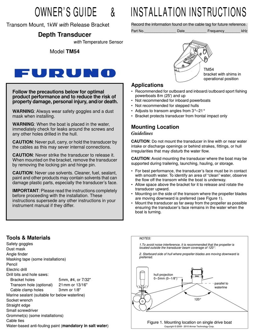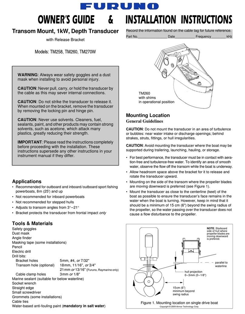
Mounting Location
Placement Guidelines
CAUTION: Do not mount the transducer in line with or near water
intake or discharge openings or behind strakes, fittings, or hull
irregularities that will disturb the water flow.
CAUTION: Do not mount the transducer in line with trailer rollers
or bunks that may damage the transducer’s face.
Choose a Location
• Where the hull is flat or nearly flat, so the transducer beam will
be aimed straight down.
• Where the water flowing under the hull is smoothest with a
minimum of bubbles and turbulence (especially at high speeds).
• Where the transducer will be in contact with the water at all times.
• Where the transducer beam will not be blocked by the keel or
propeller shaft(s).
• In a cool well-ventilated area away from the engine to avoid
overheating.
• Away from interference caused by power and radiation sources
such as: the propeller(s) and shaft(s), other machinery, other
echosounders, and other cables. The lower the noise level, the
higher the echosounder gain setting that can be used.
• Where there is working space inside the vessel.
Boat Types (Figure 1)
•Displacement hull powerboats—Locate amidships near the
centerline. The side of the hull where the propeller blades are
moving downward is preferred.
•Planing hull powerboats—Mount well aft, on or near the
centerline, and well inboard of the first set of lifting strakes to
ensure that the transducer will be in contact with the water at
high speeds. The side of the hull where the propeller blades are
moving downward is preferred.
Outboard and I/O—Mount just forward of the engine(s).
Inboard—Mount well ahead of the propeller(s) and shaft(s).
Stepped hull—Mount just ahead of the first step.
Installation in a Welded Tank
Each hull is different. Professionally install the transducer
following accepted practices.
Installation in a Cavity
Pre-molded Cavity
If the boat has a pre-molded cavity in the hull to receive the
transducer, go to “Making a Faceplate” below.
Making a Cavity
1. Using the template, cut along the “cutting line for hull cavity”
(outermost line). Tape it to the hull at the selected mounting
location.
2. Cut a hole in the hull.
3. Create a strong watertight cavity to hold the transducer.
Making a Faceplate
A faceplate is required to ensure the transducer is held within
the cavity when the boat istraveling at high speed.
1. Make a faceplate using a strong material suitable for below the
waterline such as 316 stainless steel or glass-fiber reinforced
epoxy FR4 or G10. The faceplate must be thick enough to fill the
lip of the transducer [6mm (1/4")] after marine sealant is applied.
2. Cut the opening in the faceplate using the template supplied.
Follow the “Transducer lip: cutting line for the opening in the
faceplate.”
3. Drill holes for the fasteners that will hold the faceplate securely
to the hull. Fasteners must be suitable for below waterline.
Dry Fitting
The transducer must be flush with the bottom of the hull for good
performance. Dry fit the transducer in the cavity before installing.
1. Position the template within the cavity. Tape it in place.
2.
Using the appropriate drill bits, drill holes through the cavity for
the cables
.
3. From outside the hull, thread the transducer cable through the
hole in the mounting cavity (Figure 2). Push the transducer into
the cavity as far as possible.
Measure the gap between the face of transducer and the outside
of the hull (as if the transducer is flush to the exterior hull
surface). This will be the thickness of marine sealant that must
be applied to the cable side of the transducer, plus an additional
3mm (1/8") to fill any empty spaces.
Figure 3. Bedding and installing
Copyright © 2019 Airmar Technology Corp.
inboard
Figure 1.
displacement hull
Best location for the transducer
stepped hull
outboard and I/O
Copyright © 2006 Airmar Technology Corp.
Bedding & Installing
CAUTION: Be sure the surfaces to be bedded are clean and dry.
1. To ensure that the marine sealant will adhere properly, sand the
area around the hole in the hull, inside and outside. On the
transducer, sand all the surfaces that will contact the hull. Sand
the lip of the transducer (Figure 2). Do not sand the face.
Remove all dust using atack cloth. Do not use alcohol on the
transducer.
2. Apply marine sealant to the following surfaces to seal the hull
and hold the transducer firmly in place (Figure 3).
• Cable side of the transducer—Apply the amount of marine
sealant determined by dry fitting the transducer in the cavity,
plus an additional 3mm (1/8").
•Apply 6mm (1/4") of marine sealant to the transducer
surfaces that will contact the cavity, including the lip.
•Apply 6mm (1/4") of marine sealant to the cable fittings,
being sure the marine sealant extends 6mm (1/4") outside of
the cavity and into the hull.
•Apply 3mm (1/8") of marine sealant to the side of the
faceplate that will contact the hull and the transducer’s lip.
• Apply 3mm (1/8") of marine sealant to the fasteners that will
hold the faceplate to the hull.
3. From outside the hull, thread the transducer cables through the
appropriate holes in the mounting cavity. Push the transducer
into the mounting cavity and seat itfirmly within the recess.
The
transducer’s face must be flush with the outside of the hull for
good performance. If necessary, apply additional marine sealant
to the cable side of the transducer.
4. When the boat is underway, especially at high speeds, water
will enter any gaps between the transducer and the hull and
push against the transducer with considerable force. From
outside the hull, fill any gaps between the transducer and the
cavity with marine sealant.
5. Fasten the faceplate to the hull.
6. Remove the excess sealant on the outside of the hull to ensure
smooth water flow under the transducer.
Cable Routing & Connecting
CAUTION: If the transducer came with connectors, do not remove
them to ease cable routing. If a cable must be cut and spliced, use
Airmar’s splash-proof Junction Box No. 33-035 and follow the
instructions provided. Removing a water-proof connector or
cutting a cable, except when using a water-tight junction box, will
void the transducer warranty.
1. Route the cables to the echosounder being careful not to tear the
cable jackets when passing them through the bulkhead(s) and
other parts of the boat. Use grommets to prevent chafing. To
reduce electrical interference, separate the transducer cables
from other electrical wiring and the engine(s). Coil any excess
cable and secure it in place with cable ties to prevent damage.
2. Refer to your echosounder owner’s manual to connect the
transducer to the instrument.
Checking for Leaks
When the boat is placed in the water, immediately check around
the transducer for leaks. Note that very small leaks may not be
readily observed.Donot leave the boat in the water for more than
3hours before checking it again. If a leak is observed, repeat the
installation procedure immediately.
Maintenance & Replacement
Anti-fouling Coating
Surfaces exposed to salt water must be covered with an anti-
fouling coating. Use a water-based anti-fouling coating made for
transducers only. Never use ketone based anti-fouling paint, since
ketones can attack many plastics possibly damaging the
transducer. Brush on anti-fouling coating every 6 months or at the
beginning of each boating season.
Cleaning
Aquatic growth can accumulate rapidly on the transducer’s face,
reducing its performance within weeks. Clean the surface with a
Scotch-Brite®scour pad and mild household detergent, being
careful to avoid making scratches. If the fouling is severe, lightly
wet sand it with fine grade wet/dry paper.
Transducer Replacement & Parts
The information needed to order a replacement transducer is
printed onthe cable tag. Do notremove this tag. When ordering,
specify the part number, date, and frequency in kHz. For con-
venient reference, record this information near the top of page one.
Please contact your Furuno dealer to obtain parts.
2 3
Figure 2. Dry fitting
Copyright © 2019 Airmar Technology Corp.
transducer
hull
cable (3)
lip
transducer
cable (3) marine
marine
sealant
face
cavity
hull
faceplate
face
cavity
thickness of marine sealant to be applied
to the cable side of the transducer,
plus 3mm (1/8") to fill any empty spaces
fastener
sealant
(4 or more)
