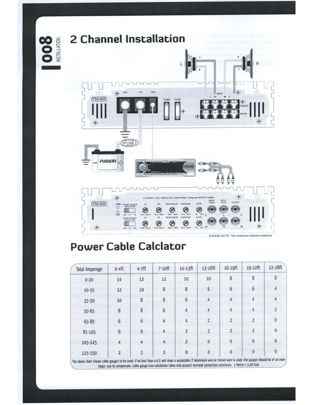
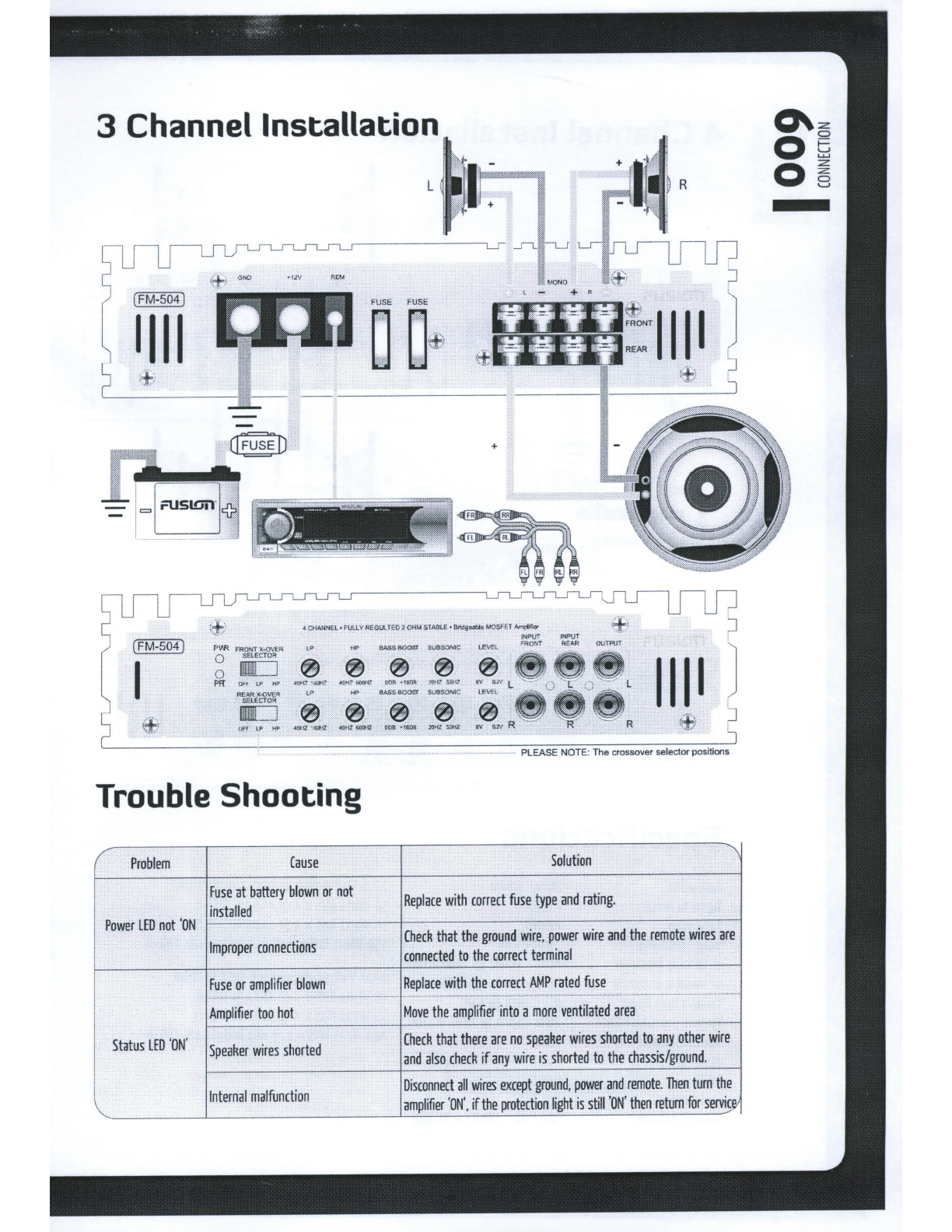
Fusion FM-504 User manual
Other Fusion Amplifier manuals

Fusion
Fusion SG-DA12250 Guide

Fusion
Fusion MS-AM504 User manual

Fusion
Fusion MS-AM806 Technical manual

Fusion
Fusion Signature Series User manual

Fusion
Fusion MS-AM402 Guide

Fusion
Fusion NV Series User manual

Fusion
Fusion MS-AM402 Guide

Fusion
Fusion SG-DA51600 Operating manual

Fusion
Fusion PowerPlant PP-AM120040 User manual

Fusion
Fusion FUS-MS-AM504 Guide

Fusion
Fusion Encounter EN-AM3002 User manual

Fusion
Fusion FM-402 Guide

Fusion
Fusion MS-AM504 Guide

Fusion
Fusion PowerPlant fp Series User manual

Fusion
Fusion SG-DA82000 User manual

Fusion
Fusion FM-504 User manual

Fusion
Fusion MS-DA51600 User manual

Fusion
Fusion SG-DA41400 Manual

Fusion
Fusion SG-DA61500 User manual

Fusion
Fusion SG-DA12250 Guide