WARNING
Failure to follow these safety precautions may result in severe injury to
yourself and others.
Check that there is sufficient battery capacity.
Do not operate the model and transmitter steering wheel
for about 3-5 seconds after turning on the GYD470 (When
shared with the receiver).
• GYD470 initialization and neutral position reading. The GYD470 is initialized when the
power is turned on. The neutral position is also read at the same time. If initialization
ends normally, the operator is informed by two repetitive movements of the servo to
the left and right (a little).
Always check the direction of operation of the gyro.
Do not strike the gyro with a hard object. Do not drop it onto
a concrete surface or other hard floor.
• The sensor may become damaged during strong impacts.
Do not use trims or mixing.
• All corrections are made by the gyro. Therefore, if trimming and mixing, are turned on,
operation will be the same as deviating from the neutral position.
Do not use the GYD470 for applications other than RC cars.
•This gyro is designed for RC cars only. Do not use it for other applications.
Analog servos cannot be used.
•The use of analog servos may cause servo trouble.
Do not place gyro near heating equipment (engine, motor,
ESC, battery, servo, etc.).
• Always allow the gyro to adjust to the surrounding environmental temperature before
ight. A large temperature change during use will cause drift and other operational
issues.
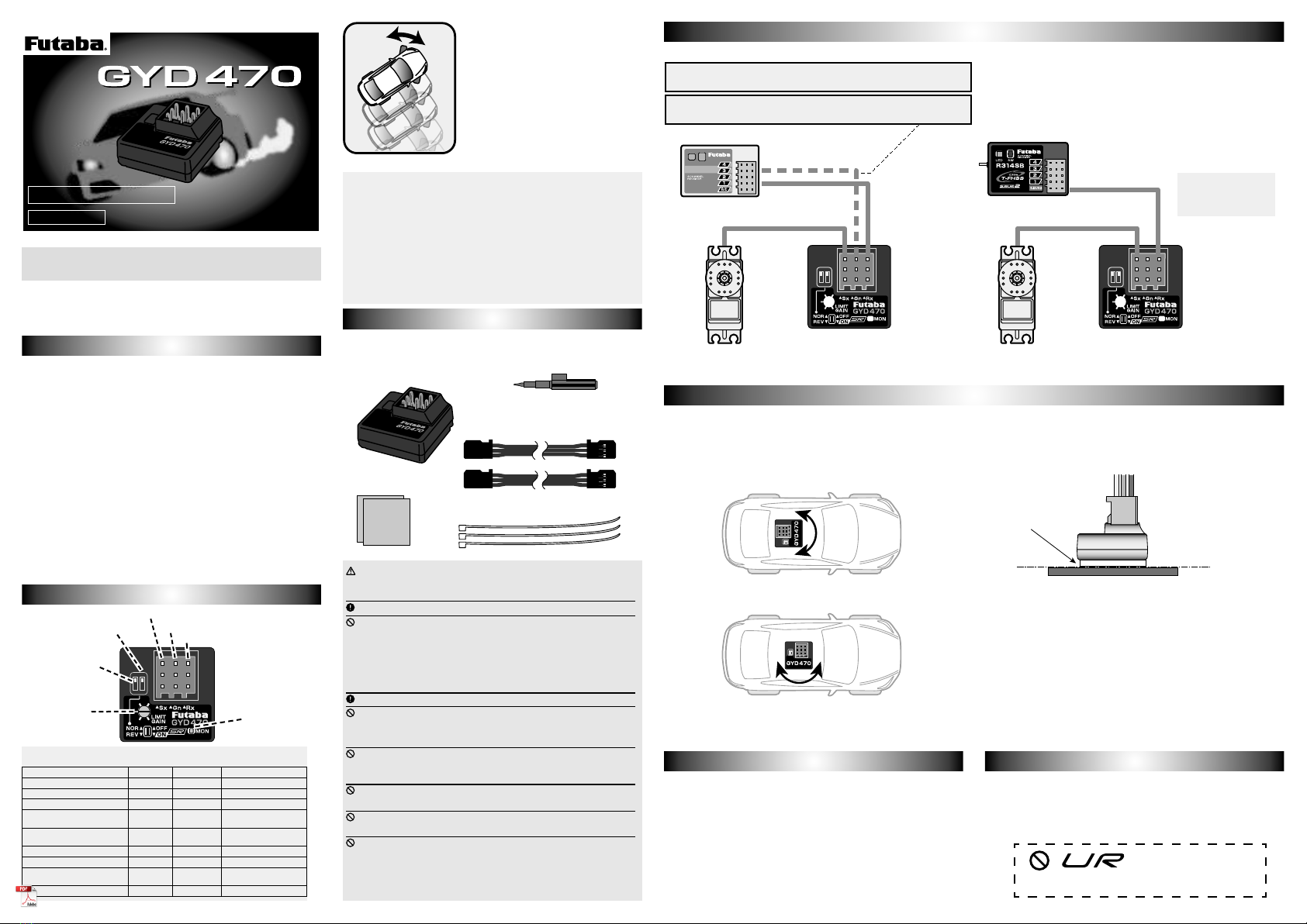
Connecting the GYD470 S.BUS Connecting the GYD470Connecting the GYD470 S.BUS Connecting the GYD470
Mounting to ChassisMounting to Chassis
Steering servoSteering servo SR modeSR mode
Rate Gyro for RC Drift Cars
INSTRUCTION MANUAL
INSTRUCTION MANUAL
Only for Futaba digital servoFor RC modelsGyroIncluded sponge sensor tapeDegrease and stickHorizontal planeFlat surface of the chassis where the sensor tape sticks easily. Mount the gyro level so that it is not tilted relative to the chassis.Use the included double-sided sponge tape to rmly at-tach the gyro perpendicular to the control axis, at a posi-tion where there is as little vibration as possible. Make the Gyro mounting positionThe direction of rotation fixed by the gyro can be any direction within 360°relative to the steering axis controlled by the gyro.•Nopartofthismanualmaybereproducedinanyformwithoutpriorpermis-sion.•Thecontentsofthismanualaresubjecttochangewithoutpriornotice.•Futabaisnotliableforanypotentialdamage(accidentalorotherwise)thatmayoccurafterinstallation.Before using your new gyro, please read this manual thoroughly and
use the gyro properly and safely. After reading this manual, store it in
a safe place.
● Dedicated RC Drift car settingVehicle straight-line and cornering performance can be increased without
taking into account the effect of the road surface, etc.
● Remote gain function and mode switching functionYou can adjust gain from the transmitter (3 or more CH) by using the
remote gain function. Gain can also be adjusted with the trimmer on the
GYD470. The mode switching function allows AVCS/NORMAL gyro mode
switching.
● Integrated, compact, and light weightCompact size(20.7x20.7x11mm)and light weight(3.7g)realized by
high density mounting technology.
● Easy setupThe GYD470 can be used immediately with minimum setup.
● Supporting the S.BUS/S.BUS2 connection
Only one wire connection to the receiver can operate the GYD470.
● Only for Futaba digital servoGYD470 Ratings:(Integrated sensor type rate gyro)
• Gyro sensor: MEMS vibrating structure gyro
• Operating voltage: DC4.0 V to 8.4 V
• Current drain: 30 mA (excluding a servo)
• Operating temperature range: -10ºC to +45ºC
• Dimensions: 20.7 x 20.7 x 11.0 mm (0.82 x 0.82 x 0.43 in) (except protrusion)
• Weight: 3.7 g (0.13 oz)
• Functions: Sensitivity trimmer. LED monitor. Servo selection (SR mode
ON/OFF). S.BUS/S.BUS2 connection.
Features of GYD470Features of GYD470
FunctionsFunctions
●Trimmer
(Limit/Gain)●LED
●Servo selection switch
(SR mode ON/OFF) ●Port1(Steering input/
S.BUS input)●Port2(Gain input)●Port3(Steering servo output)●Gyro direction
Switch
Set ContentsSet Contents
The following items are supplied with the GYD470:
Mini screwdriver
Sensor tape
Extension cord
Nylon strap
GYD470
1M23N38406Thank you for purchasing the
GYD470 RC cars gyro. Compact
and lightweight, the GYD470 is
designed to control steering for RC
Drift cars. If the transmitter has 3
or more channels (capable of 3CH
adjustment) the gyro sensitivity can
be adjusted from the transmitter.
Features include simple set-up and
S.BUS/S.BUS2 connectivity. S.BUS/S.BUS2 portGYD470GYD470S.BUS Receiver
Steering servoSteering servo
Steering CH1Gyro gain CH3ReceiverGyro gain CH(Receiver)←connect→Port2(GYD470)Remote gain eective. Trimmer(GYD470) becomes LIMIT.Gyro gain CH(Receiver)←It does not connect→Port2(GYD470)Remote gain is invalid. Trimmer(GYD470) becomes GAIN.S.BUS CHSteering --- 1CHGyro gain --- 3CHExtension cordIn S.BUS connection, the port 2 is not connected. Remote gain is still effective.wiring loose and bundle it with the included nylon strap so that it will not interfere with the rod.Link the servo in accordance with the kit instruction man-ual. Adjust the linkage rod so that the trim amount is as small as possible.When using S.BUS servo, initialize a parameter.Make the servo operating range as wide as possible. Make the numerical value of EPA (ATV) equally in left and right.Monitor LED display
State Color Move Reference
1. Power ON Orange 2 blinks
2. No servo pulse / Error Red Slow blink
3. Signal input from receiver Green Fast blink
4. Sensor initialization Red/Green ON AVCS (Red)
Normal (Green)
5. Turn Red/Green Fast blink Right (Green)
Left (Red)
6. Neutral offset Orange Slow blink Steering operation
7. Gain off -OFF
8. Switch operation Green One blink Each time of switch
operation
9. Low battery Red One flash Less than 3.8 V It is possible when using the S.BUS setting compatible transmitter to change the servo to "SR Mode" and improve the servo response. If the servo can't be changed to SR mode, do not set the TX to SR mode. Not compatible with UR mode


