FUTABA T4 User manual

FUTABA
4/5CHANNEL-DIGITAL
PROPORTIONAL
MANNUAL

*Modern,Lightweight,easy to holdtransmitter
*Transmittercasedesignedsothatcontrolsticksareina conve-
nientoperatingposition.
*Antennaisangledformore effectiveradiationpattern.
*Built-intransformertypebatterycharger.
*Controlstickknobssuppliedintwolength.
*Maximumtransformeroutputforpositivecontrol.
*Receiverhasautomaticgaincontrol(AGC)circuitformaximum
noisesuppression.
*Compact,lightweightreceiverandservos.
*Totalairborneweightis15oz.
*Transmitterhasanoutputmeter.
*Nickelcadmiumbatteriessupplied.
*Linearactionservos.

SPECIFICATION FOR FUTABA
4/5CHANNEL DIGITAL PROPORTIONAL RADIOS
•TRANSMITTER:
T4 orT5
Size:71/7" x 6"x 23/4" (exclusiveof antenna)
Weight:31bsincludingbatteries
Voltage:9.6voltDC
Pulsewidth:1.5 ms neutralvaried1msforfullcontrol.
•RECEIVER:
Size: 2.340"x 0.835"x 1.580"
Weight: 1.5 oz.
Voltage: 4.8volts DC
•SERVOS:S2
Size: 2.250"x 1.50 x 0.830"
Weight:1.84oz.
Voltage:4.8voltDC
Traveltime:0.6second end to end.
Thrust:41lbs
•COMPLETE AIRBORNE SYSTEM:
Consist ofreceiver,4 servos andbatterypack includingswitchand
harness.
Weight:15oz with500 MAHNickelCadmiumbatterysupplied.
Voltage: 4.8voltsDC.

BATTERIES:
Before initialhook-upandoperationalcheck,transmitterand receiver
batteriesshouldbe chargedfor24 hours.
CHARGING INSTRUCTIONS:
Yourtransmittercontainsa built-intransformertype nickelcadmium
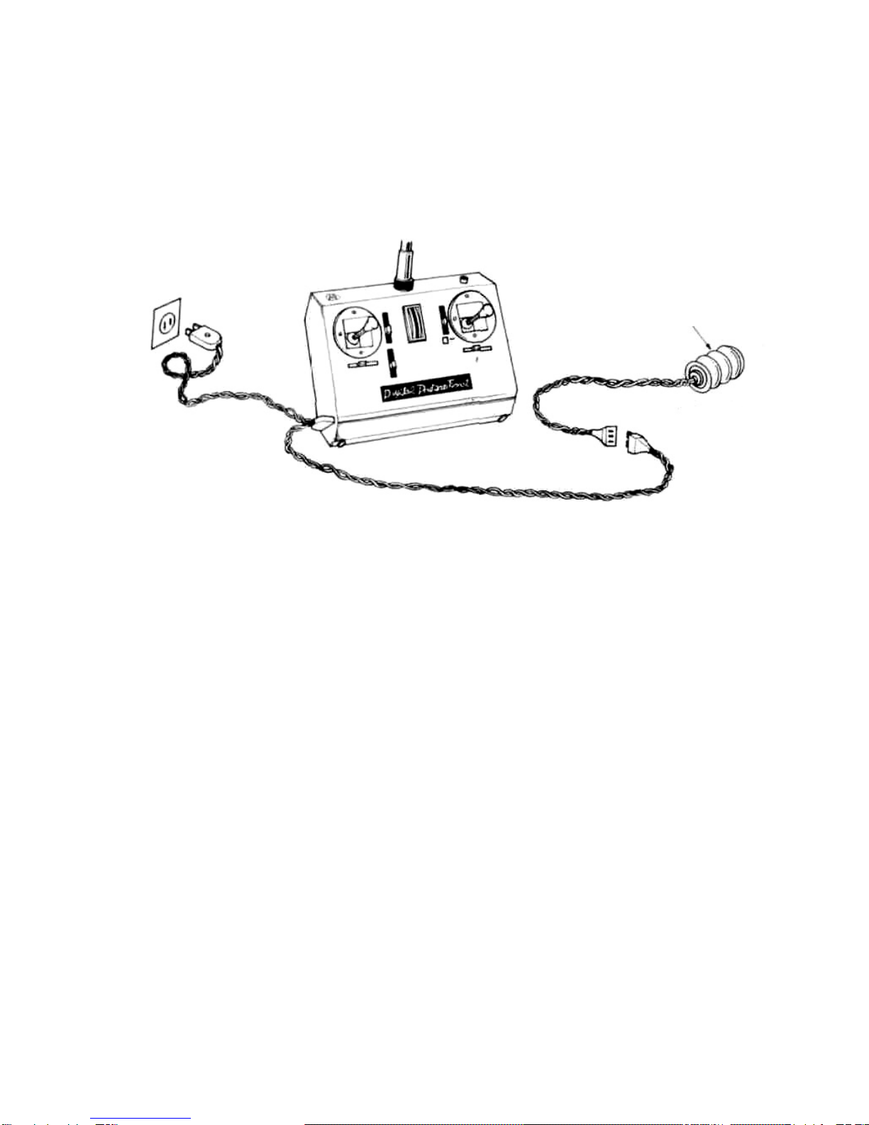
batterycharger.A dualchargingcord is packedwithyourradiocont-
rolsystem.If youwillexamine,thechargingcord,youwillnotethat
itis fittedwitha standard110volt 2 pronglinecordplug,a seven
pinmaleanda fourpinfemaleconnector.The linecord plugconnects
to
any 110-117
volt
AC. householdoutlet.Theseven
pin
male
plug
con-
nectsto thereceiverbatterypack.Thefemaleconnectorlocatedon
the lowerleft-handside on the transmittercase.
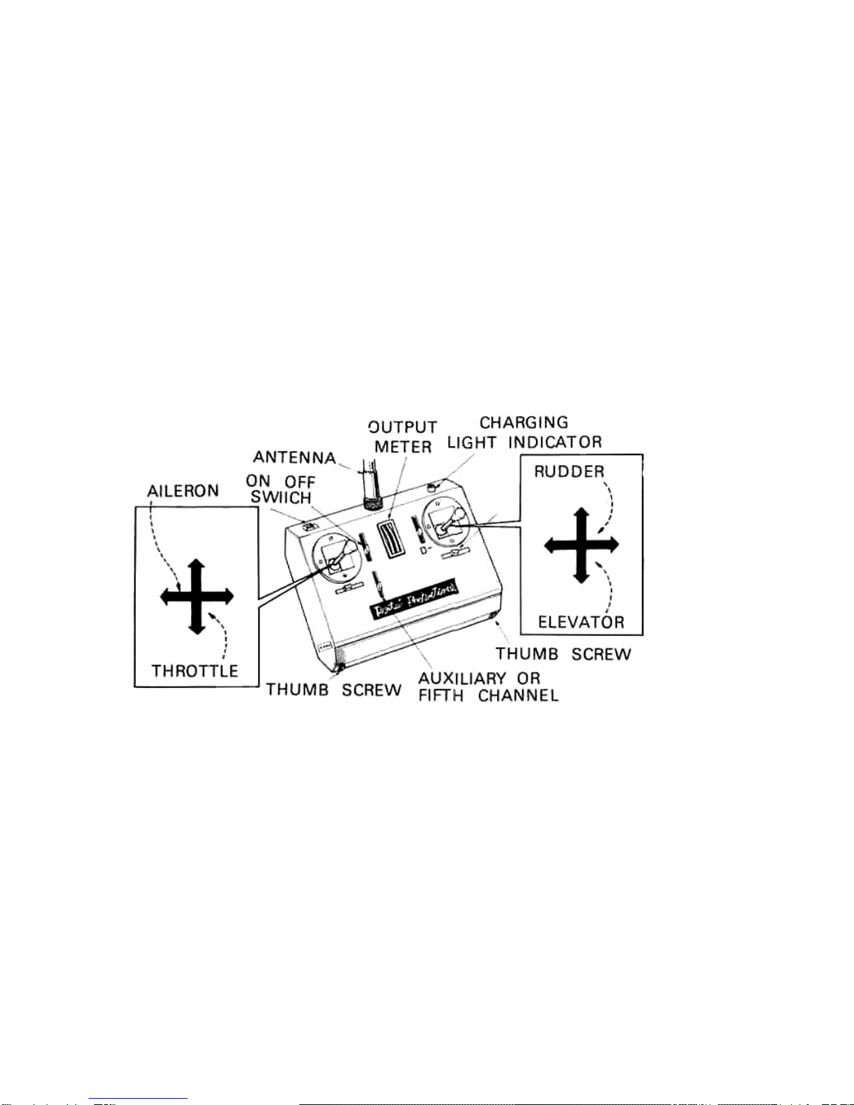
Before connectingthe chargingcord, turnthe transmitterswitchoff
andturnthereceiverswitchto theon position,(ifyourswitcharen't
intheproperposition,yoursystemwon'tcharge.)Next,plugthe4
socket connectorto the transmitterandthenthe7 pinplugintothe
receiverbatterypack.Thenyouplugthelinecord pluginto110volts
AC householdoutlet.Checkthechargingindicatorlightlocatedatthe
top righthandsideof thetransmitter,whenthislightison, itindicates
thatbothbatteriesarebeingproperlycharged18to 24 hoursissuffi-
cientfor100%chargeand thiswilloperatesyoursystem for3 hours.
"ON"FOR CHARGING
BATTERY PACK

TRANSMITTER:
LOCATED ONFRONT PANEL:
Two controlsticks-4trimlevers-one lever forauxiliary(5th) channel
operation-outputmeter.
TOP PANEL:
On-offswitch-Antennamount-Charginglightindicator.
BOTTOM PANEL:
Two thumbscrews.Removingthese screwsallowsacessto batterycom-
partment,
SIDE PANNEL:
Leftsidecontainsbatterychargingconnectors.
THECONTROLSPROVIDETHEFOLLOWINGFUNCTIONS:
The lefthandcontrolstickoperate throttleand aileron.To the right
of thisstickis a trimleverwhichcontrolstheidlepositionof the
throttleservo.Directlybelowthestickisthetrimleverforaileron.
The righthandcontrolstickoperatesrudderandelevator.The trim
leverlocatedto theleftof thisstickcontroltheneutralpositionof
the servowhichis activatedby movingthestickvertically.The trim
leverlocateddirectlybelowtherightcontrolstickis usedto control
the neutralpositionof the servo thatis activatedby movingthestick
horizontally.Theauxiliaryor 5th channeliscontrolledbythelever
locatedJustbelowandto theleftof theoutputmeter.See diagrama-
bove. Each ofthe fourmaincontrolsis trimmableby thefourtrimle-

vers.
The
auxiliary
or
5
channel
is
notindependentlytrimmable.
Two
sets
of
controlstick
knob
of
differentlengths
are
supplied
with
this
system,sinceindividualpreferencesforcontrolsticklengthmayvary.
Stickknobmaybe interchangedby merelypullingtheknobdirectlya-
wayfromthestick.The replacementknobshouldbe pushedonto the
stickuntilitis fixed.
RECEIVER:
This receiverhasbeen factorytunedand adjustedto the transmitter,
no furtheradjustmentsarerequiredandthe receivershouldnotbe tam-
peredwith.Attachto the receiveristheantenna,one 7pinplugand
2jacks.Thesevenpinplugconnectsthe receiverbatterypackand
supplies
power
to
the
receiver
and
servos.
The
multi
connectors
jack
is fortherudder,throttle,elevatorand auxiliarythe aileronservo.
See diagrambelow.
Note:Receiverconnector has a whitedot onone end. For auxiliary
(5th) channel,plugservointothisend of connector.
OPERATION CHECK:
1.Connect servo plugs to receiverjack,nextconnectreceiverto bat-
terypack.
2.Collapsetransmitterantennaandturntheswitchon.Nextturnthe
receiverswitchon.Allservosshouldstopattheneutralposition.
3.Make surethateachof the servos operatescorrectlyandrespondsto
the individualstickandtrimlever.Thistestshouldbe performedat
least20 yardsfromthereceiver.Don't testforlongerthan5 minutes.
Futaba FP-T4 and FP-T5 areveryhighputtype transmitters.

The receivershouldbe loosely mountedinfoamrubberor foam pl-
asticto protectagainstvibrationandshock.Batterypackshouldalso
beprotectedfromvibrationby wrappinginfoamrubber.The receiver
shouldalsobe protectedfromfuelbywrappingit ina plasticbag.
The
receiver
antenna
mustbe kept
as
far
as
possible
from
otherwiring
and metalparts.Excessiveelectricalnoiseisgeneratedbymetalto
metalconnectionsandmayseriouslyinterferewithreceiverreception.
Suchmetalto metalcontacts,such as throttlelinkage,shouldbe made
withnylondevicesThisreceiverhasoneof themostnoiseresistive
circuitson themarketbutcareshouldbe takento keepelectricalno-
ise ata minimum.
PRE-FLIGHT CHECK:
The finalcheckof thesystemshouldbe performedwiththeengine
runningata distanceof 20—30yardswithtransmitterantennaret-
racted. Ifthe distanceis substantiallyless thanwithenginenotrunn-
ing,youcanbe suresomethinginyourinstallationis causinginter-
ferencefromexcessivevibration.
Whenallthe above test are concludedsatisfactorilyyou areready
foryourfirstflight.If youhavenopreviousexperiencewithpropro-
tionalequipment,anexperiencedflyershouldbe enlistedto perform
the initialflyingandtrimmingof the craft.

REPAIR SERVICE
To insurepromptservice,please followthe instructionslistedbelow.
The gearsforrepairingshouldbesent backto thedistributoror local
dealer.
1.Chargebatteriesforatleast18hourspriorto the despatch.
2. Returnonlythe system,separatefromyourinstallation.Remove
servosfrommounts,removefoampaddingfromreceiver.
3.Plugsor othermodificationswhichinterferwithfactorytesting
procedureswillbe returnedto factorystandardsatyourexpense.
4.Carefullypackallcomponentsindividuallywithsufficientpacking
materialto preventshippingdamage.Warrantydoesnotcoverany
componentsdamagedintransit.Also,foryourownprotection,insu-
re allpackages.
5.Includea briefhutthoroughexplanationof allproblemsandservice
requiredandtapeto backoftransmitter.Labelservosas to their
function.
6.
Be
sure
to
include
your
full
address
inside
the
box
as
well
as
out-
side.
7.Includea packinglistof allitemsbeingreturnedanddoublecheck
to make sure allitemsarepackedforreturn.

yourdealer
This manual suits for next models
1
Table of contents
Other FUTABA Radio manuals