MANUAL WS6300 [EN] www.futech-EASY.com
- Usually, you should use the standard stud detection mode first before using the high sensitivity mode. If the sensitivity
is not high enough, you can switch to the high sensitivity mode. But keep in mind that in the high sensitivity mode
the unit may be interfered with, if the material of the wall is not homogeneous.
- Avoid interference by removing your other hand from the unit while using it.
- Remember that studs or joists are normally spaced 16-24” (41-61 cm) apart and 3.8 cm in width, so anything closer
together or of a different width may not be a stud.
- Doors and windows are commonly constructed with additional studs and headers for added stability. The unit detects
the edge of these double studs and solid headers as a single, wide stud.
- Depending on the proximity of electrical wiring or pipes to the wall surface, the unit may detect them in the same
manner as studs. Caution should be used when nailing, sawing or drilling into walls, floors and ceilings that may
contain these items.
- When the unit detects a metallic stud/object, the icon will appear on the display (in any stud detection mode).
If the icon appears on the display, the calibration has failed. Move the unit a few inches right or left,
release the TEST button [D] and then start over (Steps 2.1 to 2.12).
3 DETECTING METALLIC OBJECT
3.1 Place the unit flat against the wall surface (the surface should be flat and dry).
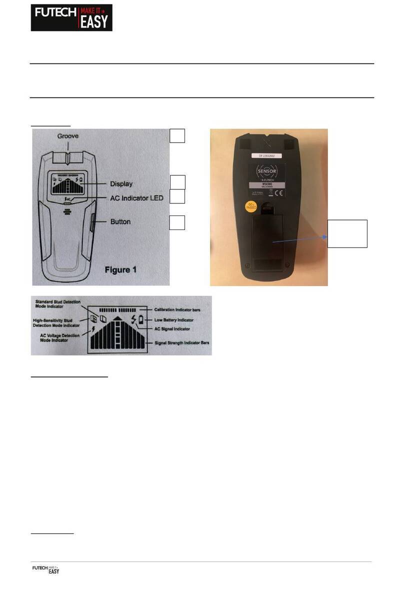
3.2 To select the metal detection mode, press the TEST button [D] until the icon appears on the display [C].
3.3 Before the unit turns off, press and hold the TEST button [D]. The unit starts calibrating, shown by the icon on the
display [C].
3.4 Do not move the unit until the calibration is completed.
- During the calibration, more and more indicator bars will appear on the display from right and left towards the center.
3.5 When all indicator bars are present, the calibration is finished and the built-in buzzer sounds a beep. The indicator bars will
disappear from the display [C].
3.6 Keep pressing the TEST button [D] through the following procedures.
3.7 Slowly move the unit sideways across the wall (keep it flat; do not rock or lift the unit).
3.8 As you approach an edge of a metallic object, more and more indicator bars will appear from right and left towards the
center. These signal strength indicator bars will indicate that you are getting close.
3.9 When the signal strength indicator bars peak and the built-in buzzer sounds continuously, the unit has detected an edge of
the metallic object.
3.10 Stop moving and mark the spot at the groove [A] with a pencil.
3.11 Continue to move the unit across the wall surface in the same direction until all the signal strength indicator bars has
disappeared. Then reverse direction (still holding the button in) and locate the other edge by using the same procedure.
3.12 Mark the spot at the groove [A] with a pencil (the midpoint of the two marks is the center of the metallic object).
If the icon appears on the display, the calibration has failed. Move the unit a few inches right or left,
release the TEST button [D] and then start over (Steps 3.1 to 3.12).
4 DETECTING LIVE AC WIRE
4.1 Place the unit flat against the wall surface (the surface should be flat and dry)
4.2 To select the AC voltage detection mode, press the TEST button [D] until the icon appears on the display [C].

