FUZRR ES1000 Series User manual

0

1
CONTENT
.SafetyPrecautionsand Procedures………………………‥ 3
Ⅱ. BriefIntroduction …………………………………………… 4
Ⅲ. ElectricalSymbols …………………………………………… 5
Ⅳ. TechnicalIndicators ………………………………………… 6
Ⅴ. Outline Structure …………………………………………… 7
Ⅵ. H/LVoltage ClampMeter Symbols ……………………… 8
1. Button Instructions …………………………………………… 9
2. LCD four-digit SymbolDisplayInstructions………………… 9
3. OrdinaryH/LVoltage Clamp MeterTestDisplayInstruction…10
Ⅶ.BasicH/LVoltageClampMeter OperatingInstructions …10
1. PowerOn/Off ……………………………………………… 11
2. GeneralTest …………………………………………………‥11
3. PEAKTest …………………………………………………… 13
4. Data Maintenance………………………………………………13
5. Data Storage……………………………………………………13
6. Data Reference…………………………………………………14
7. DataDeletion……………………………………………………14
ⅧSymbolsofWireless H/LVoltage ClampMeter………………14
1. InstrumentLCD SymbolDescription………………………… 14
Ⅸ.Receiver Operation ……………………………………………15
1. PowerOn/Off………………………………………………… 15
2. Data Reception ………………………………………………16
3. Data Maintenance………………………………………………16
4. Data Storage……………………………………………………16

2
5. Data Reference…………………………………………………16
6. DataDeletion……………………………………………………17
Ⅹ.Batteries ……………………………………………………… 17
Ⅺ.Accessories…………………………………………………… 17

3
. Safetyrules and precautions
Thankyou for purchasingthe company'shigh andlow voltage
clampammeter.Toavoidpossibleelectricshockorpersonalinjury,
please be suretostrictlyobservethe safetyrules andprecautions
listedinthismanual.
●Beforeuse, checkwhether the instrument isingoodcondition,
no damage,and forbidtouse beforethe backcoveriscovered.
Otherwise, thereisdanger ofelectricshock.
●Inanycase, it shouldpayspecialattentiontosafetyinuse of
thismeter, particularlyinmeasurement ofcircuitrywithmore
than AC100Vand abovevoltages.
●Ifthe voltage oftestedcircuitryhas exceeded 600V, itmust
be usedbyconnecting withan insulationrod.
●Asit isverydangerous ofhighvoltage transmission line, the
operatormust get strict training andthe relevant certification
on high-pressureoperationofthe statebeforeusingthismeter
and makingafieldtest.
●It isstrictlyforbidden tousethismeter totest the wirewithout
anyinsulateprotection orconvergence generatrix.
●Please payattention tomarked words and symbolson panel
or backboardofthismeter.
●Please donot put or storethismeter inthe placeofhigh
temperature,withmoisture,withfrozen deworwithdirect
daylight irradiationfor along time.
●Please notethe batterypolaritywhen replacing battery, and
removethe batteryifyouexpectnottouse thismeterfora
longtime.
●It must be operated byqualified staffthat has the authorization
on tearingdownor repairing thismeter.
●Checkthe housing beforeusingthe meter. Checkforcracks or

4
missing plasticparts.Ifthe head and otherpartsofthe
instrument aredamaged,please do not use it..
●Toavoidthe impact oftransducer clamp, it needs tomaintain
thismeterregularly.Donotuse corrosiveorcoarsematerials
toclean,butuse soft cloth(such as glasses cloth), dipa
lubricantthatisrust-proofand dehumidified,and gentlywipe
the meter.
●For the reason ofthismeter, incase that anydanger may
occur ifcontinue touse it, stop using it immediatelyand sealit
up forkeepingatonce,which shall be dealtwithby qualified
authorization agency.
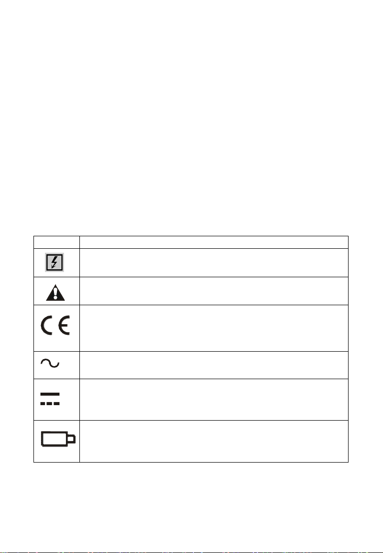
●The danger symbol on the meter and the manual, the
usermustmake safeoperation accordingtothe indication.
●The extremelydangeroussymbol ”on the meterand the
manual,the usermustmakesafeoperationaccordingtothe
indication.
●It suggeststhat thismetershallbe made insulationintensity
testatleastonceeveryyear(AC 60kV/rms fiveinsulation rods
between the twoends.)
●The manualhas awirelesstransmissiondatatype.
. BriefIntroduction
The H/LVoltageClampMeterisahigh-voltagemeasurement
toolcomposedofaspecialclampammeterequipped withahigh
voltage insulation rod.Inside the clampammeter,amask
integratedcircuitisused,and an insulatingrod isconnected to
measurethe currentofahighvoltageline withabarewireorless
than 35 kV.When notusing the insulationrod,itcanalso beused
as ahigh-precisionlow-voltageclampammeter,leakagecurrent
meter,canaccuratelymeasurethe currentof0.1mA.It has a
simpletouse, easytocarry
Itswireless transmissiontestdata,equippedwithawireless
receiver,can receivemeasured datawithin30 metersofastraight
line(withoutobstacles), ensuring high-precision,highreliability,

5
and high stabilitythroughout the year..
The H/LVoltage ClampMeteralsohas functions such as peak
hold,dataretention,datastorage,wireless transmission,etc.Its
specialclampammeter canfacilitateclamping or evacuation ofthe
measured wirebypushingorretracting theinsulation rod,saving
timeand fast.
It can be widelyused insubstations,powerplants,industrial
and miningenterprises andtesting stations,electricalmaintenance
departmentsforcurrentdetection andfieldelectricalwork.
Insulation rodsarelight, moisture-proof,high-temperatureresistant,
impact-resistant, bend-resistant, and highlyinsulating.
Ⅲ. ElectricalSymbols
Symbol
Meaning
Dangerous voltage(Riskofelectricshock)
Warning attention safetysign.
ComplywithEUCommunitySafetyStandards.
AlternatingCurrent (AC)
Direct Current (DC)
Battery, when indicated, means low battery

6
Ⅳ.TechnicalIndicators
Model Range of
measurement Accuracy Jaw
Specification
BaseModel 0.0mA-1200A 0.1mA Φ50mm
WirelessModel 0.0mA-1200A 0.1mA Φ50mm
Insulation sheathwiretestbelow60kVline voltage,barewiretest
below 60kV(withinsulationrod operation)
1.Jaw Specification: Φ50mm
2.Range ofmeasurement: 0.0mA-1200A(50/60HzAuto
Identification)
3.TestAccuracy: ±2%±5dgt
4.Sampling Speed:About 2times/second
5.Meter Dimension:W/T/H:87mm×37mm×262mm
*6.Receiver Dimension:W/T/H: 100mm×35mm×204mm
7.LCDDimension: 47mm×28.5mm
*8.Wireless Receiver DisplayDimension:62mm ×44mm
9.InternalBattery: DC6V4alkaline batteries, 7th,Wireless
Receiver: 51.5V5alkaline batteries
10.MeterTotalWeight:2.5kg ( including insulating rod and
battery)
11.Insufficient Voltage: LCDdisplay" " symbol
12.WorkTemperature: -10 ~40

7
13.StorageTemperature: -10 ~60
14.RelativeHumidity: 0℃~31℃≦75%,31℃~40℃≦50%
*15.Wireless Distance: 30m
16.Insulating Rod:Fivesectioninsulation rods (5metersintotal)
InsulationstrengthAC60kV/rms
Parameter withsymbol*isfor the wireless model
Ⅴ. OutlineStructure
Base ModelWirelessModelReceiverforWirelessModel

8
NO. Description
①Clamp Jaw
②Base Type:LCD Display
③PEAKTestIndication
④PEAKKey
⑤Insulation Rod Connector
⑥POWERKey
⑦Wireless Type LowBatteryIndication
⑧Wireless Type PowerIndication
⑨Wireless Type HOLDKey
⑩Wireless ReceiverLCD Display
Insulation Rod(total5m)
Ⅵ.H/LVoltageClampMeterSymbols
1. Button Instructions
POWER Press the POWER button toturnon the LCD
displayand enterthe normaltestmode.
PEAK Peak hold
LOWBATTERY
Low-powerdisplaylight
HOLD Data retention function (wireless model)
2. LCD four-digitSymbolDisplayInstructions

9
Lowbatteryvoltage symbol,when thebatteryvoltage islower
than 5.5V,thissymbolshows,pleasereplace the batteryin
time
MEM Data storage symbol
MR Data access symbol
mVA Unit symbol
AC Alternating currentsymbol
HOLDData retention
DC Directcurrentsymbol
3.OrdinaryH/LVoltageClampMeterTestDisplay Instruction
StatusSymbol Instrucion
The measuredcurrentexceedsthe upperlimit of
the meter
When the memorydataisfull of100 groups,the
"FULL" symbolflashesand datacan no longerbe
stored
Data clearsymbol, displayedduring clearing
The measured currentis0.1mA

10
Lock the displaydata. Thisdataisautomatically
stored asgroup 08. Themeasured currentis:
100.6A
The measured currentis:486Abatteryvoltage
lowsymboldisplay,pleasereplace the batteryin
time
Reviewthe stored 08thsetofthe measured
current, it sdata is:100.6A
Ⅶ.Basic H/LVoltageClampMeterOperating Instructions
Please checkall partsofthe metercarefully
beforeusage,tosee whetherthereisany
damage.Andmake sureno damagebefore
usage.
According tomanualinstructionstoinstall the
battery
Test Operation

11
1. Power On/Off
Press POWER button topoweron,theinstrumentwill
displaysthe LCDscreen,enteringnormaltestingmode.If
LCDdisplayisrelativelydarkafter power on, it ispossiblethat
batteryvoltage isabitlower.Please replacebattery.15
minutesafterpowering onthe meter,if itremainsidle,an
auto-poweroffprocedurestartstopreservethe batterylifeand
LCDwillcontinueflash untilthe completeswitchofftakes
placeafter30seconds.Incase ofLCDcontinuous flash,
press POWER button, then the meter willcontinue towork.
Under generaltest mode,press POWER button topower
off. Inthe power-on state, press and holdthe HOLDbutton
for along time.After releasing, enter the dataaccessmode.
Inthe datareferencemode, press the HOLDbutton and the
POWERbutton tocheckthe datamode. Press and holdthe
HOLDbutton toreturntothe normaltestmode,and then press
the POWERbutton toshut down.
2.GeneralTest
High voltage,extremelydangerous!It mustbe
operatedbyqualifiedstaffthathasacquired
authority.The operatormuststrictlyabide bythe
safetyrules.Otherwise,thereiselectricinjury
danger,causing personaldamageorcasualty
accident.
Dangerous!It cannotbe used tomeasurethe
circuitover60KV voltage.Otherwise,thereis
electricinjurydanger,causing personal damage
or equipment damage.
Dangerous!It cannotbe used tomeasurethe
circuitover1200Avoltage.Otherwise,thereis
electricinjurydanger,causing personal damage
or equipment damage.
GeneralTest: Inthe process oftest, LCDwilldisplaythe
tested currentvalue realtime,andLCDdatawillvarywiththe

12
currentchange.When thetesterisremoved away fromthe
leadontest, itdoes notpreservethe testresult, LCDdisplay
will returntozero.
Innormaltesting mode,itissuitableforclose distance
measurement, convenient for circuit test bydirect read ofLCD
data.
Beforetest, firstlytoconnectinsulationrod,
which mustbe connected inrightposition,and
then toconnecttester,avoidingthe impactof
meter toground surface.
Makesuretouse speciallyequipped insulation
rod toconnect withthe meter.
Aftertest, itshouldincline the insulation rod
accordinglyon drawingin.Firstlytoteardown
the testerand then the insulation rod,avoiding
the impact ofmeter toground surface.
Afterthe normalstart-up,letthe wirebe inthe middleof
the clampguide area,the instrumentguidearea is
perpendiculartothe wire, push the meterforwardtoclampthe
measured wire,and the LCDshowsthemeasurementresult.
If OLA”isdisplayed,the measured conductorcurrent
exceeds the upperlimitofthe gear.Please selecthigh-endor
higherlimitmeter.Afterpulling back,the instrumentcan be
evacuated fromthe tested wire.When evacuating,the
instrumentguidearea shouldbe keptperpendiculartothe
wire..
Wire
PUSHPULL

13
Press HOLDkeytoreleasethe hand,LCD displayHOLD
symbol,enterHOLDmode,press HOLDkey toexit
measurementmode!
Press andholdtheHOLDbutton torelease,enterthe
dataquerymode.Inthedatareference mode,press and hold
the HOLDbutton torelease the exitdatareference mode and
returntothe normaltestmode.
Inthe PEAK testmode, press the PEAKkeytoexit the
PEAKtest mode andreturntothe normaltestmode.
Attention!Forthe sake ofsafety,please move
the meter awayfromthe tested wire
3. PEAK Test
PEAKtest: the maximumcurrenttest. The meterwillmake
automaticcomparison onthe changes inmeasured current,
indicating the maximumvalueand maintainit.
When the meterisremoved awayfromthe wireontest,
the testresultwill be keptconsistently,suitableforthe circuit
test on those LCDdatahardtobe read directly.
Underthe normaltestingmode,press PEAK button,
PEAK indication lightwillbe bright,,enter PEAK testing
mode.Thatmeans the meterwill displayand automatically
keep the maximumvalue inthe test.
4.DataMaintenance
Undernormaltestingmode,press HOLD button tokeep
LCDdisplay, HOLD”symboldisplays,the "HOLD"symbol
indicatesthatthe MEMflashes once and the measured current
dataisretainedPress HOLD button againtoreleasedatalock,
returningtonormaltesting mode,and HOLD”symbol
disappears.
5.DataStorage
Undernormaltestingmode,press HOLD tostoragedata,
at the sametime, Meter willautomaticallyformserialnumbers,
and memorythe currentpreserved data.During thestorage,
MEM”symbolwill showonce byflash.Thismetercan

14
memory100 groupsofdata,incase offullstorage, FULL”
symbolwill displayby flash continuously,anditcannot
continue tomemoryuntilcleaningout the previous memory.
6.DataReference
Inthe normaltestmode,press and holdthe HOLDbutton
toreleaseand enterthe datareference mode.The MR”
symbolisdisplayed.Atthe sametime,thestored 01stgroup
dataisautomaticallydisplayed.Press the HOLDbutton orthe
POWERbutton toscrollup ordownthrough the stored data.
The data,when referringtothe lastsetofstored data,
automaticallyreturns tothefirstsetofdata.Press and release
the POWERbutton torelease the datareference mode and
returntothe normaltestmode
7.DataDeletion
Inthe testmode,press andholdthe POWER buttononce
toclearallstored data.During thedataclearing process,the
dEL”symbolisdisplayed.HolddowntheHOLDbutton to
clear the data.
.SymbolsofWirelessH/LVoltageClampMeter
1. InstrumentLCD SymbolDescription
StatusSymbolInstructions
The measured currentexceedsthe upperlimit of
the meter
When the memorydataisfullof200 groups,the
"FULL" symbolflashesanddatacannolonger
be stored。

15
DataClear,ClearSelect"YFS",DoNotClear
Select"No"。
No signalreceived
The measured currentis0.2mA
Lock the displaydata, thisdataisautomatically
stored asgroup 06. The measured currentis:
27.6A.
The measured currentis:486Abatteryvoltage
lowsymboldisplay,when the batteryvoltage is
lowerthan 5.5V,thissymbolshows,please
replace the batteryin time.
The measured currentofthestored 06thdatais:
27.6A
ⅨReceiver Operation
1.Power On/Off
Press POWER button toturnon,LCDdisplay,enterthe
receivedatamode.Ifthe LCDdisplayisdarkafterpoweron,
the batteryvoltage maybelow. Replace the batteryintime.
Afterthe receiveristurned on for15 minutes,the LCD
continues toblink,indicating thatthe LCDwillautomatically
shutdown.AftertheLCD flashesfor30 seconds,theLCD will
NOSIGNAL
-- - -

16
automaticallyshutdowntoreducebatteryconsumption.Ifthe
LCDcontinues toflash,press the POWERbutton tocontinue
working.
Underdatareference,first, press POWER button(for3
seconds )toexitdatareference mode,then comebacktodata
receivemode, press POWER button onceagaintopower off.
2.DataReception
Afternormalpoweron,the receiverwill underreceiving
mode.Ifthereareemission data,the receiverwilldisplaythe
testresultrealtime.Ifithas notreceived anysignal,the
receiverwill searchsignalsconstantly,anddisplay NO
SIGNAL----”symboldynamically.
3.DataMaintenance
UnderDataReception mod,press HOLD button,keep
LCDdisplay, HOLD”symbolindication.Press HOLD button
once againtorelievedatalock,returns todatareception mode,
HOLD”symboldisappears.
4.DataStorage
UnderDateReception mode,press HOLD button to
maintaindata,meanwhile,the receiverwill automaticallyform
serialnumbers,and memorythe currentpreserved data.
During the storage, MEM”symbolwilldisplayonce byflash.
The receivercan memory200 groupsofdata,incase of
full storage, FULL”symbolwilldisplaybyflashcontinuously,
and itcannotcontinue tomemoryuntil cleaningoutthe
previous memory.
5.DataReference
UnderDataReception mode,press HOLD button for more
than 3seconds toenterDataReferencemode, MR”symbol
display,meanwhile,itwillautomaticallydisplaydatasaved in
the group 1.Then press HOLD button or POWER button to
read the stored databyturningupwards ordownwards incycle.
It will returntothe group1’sdataautomaticallyafterreaching

17
the last group’sdatainstorage.
Press HOLD button formorethan 3seconds toexit from
datareference mode, returning toreceivingdatamode.
6.DataDeletion
Underanymode,press POWER button formorethan 3
seconds,"Deletedata?"appears,clearallstoreddatalong
press "YFS"(morethan3seconds)todelete,otherwise select
"No", and returntoreceivedatamode
. ⅩBatteries
Warning!Incase thatthe battery’scover
boardisnotwell closed,itisforbidden to
make test. Otherwise, it isdangerous.
Payattention tothe polarityofbattery,incase
ofdamage tothe meter.
Donotmixinthe use ofnewand oldbatteries.
1.Whenthe batteryvoltageisbelow5.5V,the meterwill
display ” symbol,indicating thebatteries haveno
sufficient power content. Please replace batteries.
Ⅺ.Accessories
Tester 1PC
Insulation Rod1SET(5m)
Meter Bag
1PC
Tester (battery) DC6V7# alkaline
battery 4PCS
User’sManual 1SET

18
The contentsofthisusermanualcannotbeusedasareasontousethe
product forspecial purposes.
The companyisnot responsiblefor otherlossescaused byuse.
The companyreservesthe righttomodifythe contentsoftheusermanual.If
thereis anychange, it will notbe notified.
GuangZhou ZhengNeng ElectronicsTechnologyCo.
Address:2F, No.15 Baoshu Road, Taihe, Baiyun District,Guangzhou,
Guangdong, China
Toll-free call:4000-1515-38
Tel:86-20-36544172
Fax:86-20-37319075
Post:510540
WebSite:www.znele.com
This manual suits for next models
2
Table of contents
Other FUZRR Measuring Instrument manuals