Gadspot S series User manual

H.264 Super Digital Video Recorder User Manual

H.264 Super Digital Video Recorder User Manual
1
Welcome
Thank you for purchasing our DVR!
This manual is designed to be a reference tool for the installation and operation of your system.
Here you can find information about this series DVR features and functions, as well as a detailed menu tree.
Before installation and operation please read the following safeguards and warnings carefully!
Important Safeguards and Warnings
Do not place the heavy object on the DVR.
Do not let any solid or liquid fall into or infiltrate the DVR.
Please brush the printed circuit boards, connectors, fans, machine box and so on regularly. Before the dust
cleaning please switch off the power supply and unplug it.
Do not disassemble or repair the DVR by yourself. Do not replace the electronic components by yourself.
Environment
Please place and use the DVR between 0℃and 40℃.Avoid direct sunlight. Stay away from heat source.
Do not install the DVR in damp environment.
Do not use the DVR in smoky or dusty environment.
Avoid collision or strong fall.
Please insure the DVR level installation in a stable workplace.
Please install in ventilated place. Keep the vent clean.
Use within the rating input and output scope.

H.264 Super Digital Video Recorder User Manual
2
Contents
1. Production Introduction..........................................................................................................................................4
1.1 Product Overview .............................................................................................................................................4
1.2 Main Functions.................................................................................................................................................4
2. Open-package check,products understanding and cable connections.....................................................................5
2.1 Open-package check.........................................................................................................................................5
2.2 The rack installation..........................................................................................................................................6
2.3 Understanding of the front panel ......................................................................................................................6
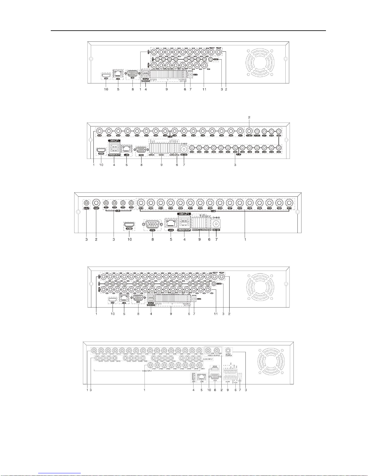
2.4 Understanding of the rear panel........................................................................................................................7
2.5 Installation connections sketch map (16CH DVR as an example the following,please prevail in kind) .....................................10
2.6 Audio and video input and output connections...............................................................................................10
2.6.1 Video input connections...........................................................................................................................10
2.6.2 Video output device selection and connection.........................................................................................11
2.6.3 The audio signal input..............................................................................................................................12
2.6.4Audio Output............................................................................................................................................12
2.7 Alarm Input and output connections...............................................................................................................12
2.7.1Alarm Input port explain..........................................................................................................................13
2.7.2 Alarm Output port explain .......................................................................................................................13
2.8 PTZ Decoder, The ball machine connection...................................................................................................13
3. Basic Operation.....................................................................................................................................................14
3.1 Starting up.......................................................................................................................................................14
3.2 Shutdown........................................................................................................................................................14
3.3 Login...............................................................................................................................................................15
3.4 Preview ...........................................................................................................................................................15
3.5 Desktop Shortcut Menu ..................................................................................................................................16
3.5.1 PlayBack..................................................................................................................................................16
3.5.2 Record Mode............................................................................................................................................19
3.5.3 PTZ Control.............................................................................................................................................19
3.5.4 Highspeed PTZ ........................................................................................................................................25
3.5.5 Color Setting............................................................................................................................................25
3.5.6 OutputAdjust...........................................................................................................................................25
3.5.7 Info...........................................................................................................................................................26
3.5.7.1 Version ..............................................................................................................................................26
3.5.7.2 HDD Info..........................................................................................................................................26
3.5.7.3 BPS ...................................................................................................................................................27
3.5.7.4 LOG ..................................................................................................................................................27
3.5.7.5 Online User.......................................................................................................................................28
3.5.8 Logout......................................................................................................................................................28
3.5.9 View 1......................................................................................................................................................28
3.5.10 View 4....................................................................................................................................................29
3.5.11 View 9....................................................................................................................................................29
3.5.12 View 16..................................................................................................................................................29
3.5.13 Hide........................................................................................................................................................29
4. Main Menu.........................................................................................................................................................29
4.1 Main Menu navigation....................................................................................................................................30

H.264 Super Digital Video Recorder User Manual
3
4.2 General............................................................................................................................................................32
4.3 Record.............................................................................................................................................................33
4.4 Network ..........................................................................................................................................................35
4.4.1 Net Service...............................................................................................................................................36
4.5 Alarm ..............................................................................................................................................................43
4.5.1 Motion Detect ..........................................................................................................................................44
4.5.2 Video Blind..............................................................................................................................................46
4.5.3 Video Loss................................................................................................................................................47
4.5.4 Alarm input ..............................................................................................................................................47
4.5.5 Alarm output ............................................................................................................................................48
4.5.6 Abnormality .............................................................................................................................................48
4.6 Switch.............................................................................................................................................................49
4.7 System.............................................................................................................................................................52
4.7.1 HDD Manage...........................................................................................................................................53
4.7.2 PTZ config...............................................................................................................................................53
4.7.3 GUI Display.............................................................................................................................................54
4.7.4 Bacckup....................................................................................................................................................55
4.7.5Account....................................................................................................................................................56
4.7.6 Device Info...............................................................................................................................................59
4.7.7 Restore.....................................................................................................................................................59
4.7.8Auto Maintain..........................................................................................................................................60
4.7.9 Upgrade....................................................................................................................................................60
4.7.10 Import/Export.........................................................................................................................................61
5. Network access settings and cloud technology introduced................................................................................61
5.1 LAN access settings........................................................................................................................................61
5.2 Cloud technology functions and using introduction .......................................................................................63
5.3 Client CMS software operation.......................................................................................................................64
5.4 Mobile Phone monitoring...............................................................................................................................66
6. FAQ and use and maintenance..............................................................................................................................68
6.1 FAQ.................................................................................................................................................................68
6.2 Use and maintenance ......................................................................................................................................74
Appendix 1. Remote controller operation.................................................................................................................74
Appendix 2. Mouse operation...................................................................................................................................75
Appendix 3. Hard Disk capability calculation..........................................................................................................75

H.264 Super Digital Video Recorder User Manual
4
1. Production Introduction
1.1 Product overview
The series DVR is designed specially for security and defense field which is an outstanding digital
surveillance product. It introduces embedded LINUX operating system which is more stable. It introduces
standard H.264mp video compressed format and G.711A audio compressed format which insures the high quality
image, low error coding ratio and single frame playing. It introduces TCP/IP network technology which achieves
the strong network communication ability and telecommunication ability.
The series DVR can be used individually or online applied as a part of a safety surveillance network. With the
professional network video surveillance software it achieves the strong network communication ability and
telecommunication ability.
The series DVR can be applied in the bank, telecom, electric power system, judicial system, transportation,
intelligent housing, factory, storehouse, water conservancy and so on.
1.2 Main functions
Real-time surveillance
·Analog interface VGA interface and HDMI interface (Optional).
·Surveillance functions through monitor or display.
. The phone wireless monitor function.
Storage
·Non-working hard disk dormancy processing which is convenient to radiate heat, reduce power and extend the
life-span.
·Special storage format which insures the data safety.
Compression
·Real-time compression by individual hard disk which insures the audio and video signal stable synchronization.
Backup
·Through SATA interface and USB interface such as USB equipment, removable hard disk and so on.
·Through net download the files in the hard disk.
Playback

H.264 Super Digital Video Recorder User Manual
5
·Individual real-time video recording as well as searching, playback, network surveillance, recording check,
downloading and so on.
·Multi-channel playback mode.
·Zoom at arbitrary region.
Net operating
·Through net tele-surveillance in the real time.
·Remote control PTZ.
·Remote checks the recording and real-time playback.
Alarm linkage
·Only one channel relay alarm output which is convenient for the alarm linkage and light control at the spot.
·protecting circuits at the alarm input and output interface which protects the main machine from damage.
Communication interface
·RS485 interface which fulfills the alarm input and PTZ control.
·Standard Ethernet network interface which fulfills the telecommuting function.
. IPC signal input function.
·With USB interface, 3G and WIFI wireless network connection (Optional).
Intelligent features
·Mouse action function.
·Fast copy and paste operating for the same setting.
. Support cloud access technology (Access Address: www.dvrcenter.net), Make network monitoring more easily.
. DVR/HVR/NVR function 3-in-1 design,A video signal input can receive multi-mode.
. Support analog signal, network HD signal.
2. Open-package check, Products understanding and cable connection
2.1 Open-package check
When you receive the DVR, please check first.
First, please check whether there is any visible damage to the package appearance. The protective materials
used for the package of the DVR can protect most accidental clashes during transportation.
Then, please open the box and get rid off the plastic protective materials. Check whether there is any visible

H.264 Super Digital Video Recorder User Manual
6
damage to the DVR appearance.
At last, please open the machine crust and check the data wire in the front panel, power wire, the connection
between the fan power and the main board.
Note: Please carefully check the bottom or back on the product type and consistency. Label affixed by
the base plate or on the rear panel, Label, has a very important significance, please protect. When contact
with our customer service, will need you to provide label type and serial number.
2.2 The rack installation
The specification of machine box is standard 1U.It can be installed in the standard frame.
Installation approach and notice:
1、Mare sure the house temperature under 40℃(104°f).
2、Keep the DVR away from other equipments at least 15 centimeters(6 inches).
3、Frame installation from bottom to top.
4、If installing multiple components in the frame, take precaution to avoid the overload of the jack.
2.3 Understanding of the front panel
Front panel button operation function table (Note: This manual is a generic manual, Please
prevail in kind).
No.
Button name
Mark
Function
1
Shift function button
SHIFT
Shift in the number button, character button and other function
button during the user under input state
2
Direction button
<
>
Remove the cursor
Add or decrease number during the user edit state
Change the setting in the menu
Surveillance pictures, into the single channel or multi-channel
image surveillance.
< >
Remove the cursor when the main menu or submenu is
popped
Remove the cursor during the playback mode
Enter former or after channel surveillance during single
surveillance image
Main menu/Confirm
button
ENTER
Confirm
Enter main menu or next grade menu

H.264 Super Digital Video Recorder User Manual
7
3
Cancel button
ESC
Back to the above level menu or cancel operation in the
operation menu
Back to the real-time surveillance during the playback state
4
Play previous file button
I
Play previous video during the playback state
5
Play next
file button
I
Play next video during the playback state
6
Slow play
►
Play in the multi-low or regular speed video during the
playback state
7
Fast play
Play in the multi-fast or regular speed video during the
playback state
8
Playback/pause button
II/
Playback the video or pause during the playback state
9
Play/pause button
/II
Play the video or pause during the playback state
10
Recording button
REC
Start/stop the video recording manually. With the direction
button choose the channel in the recording control menu
11
Recording search button
SEARCH
Search recording files
12
PTZ control button
PTZ
Enter PTZ setting, PTZ control
13
USB interface
USB
Connect USB device. Eg: USB flash drive, mouse etc.
14
Power switch button
POWER
Power switch button
15
Remote controller
receiver
IR
Receiving remote control signal
16
HDD indicator light
HDD
HDD is during working state if lighted
17
HDD information button
INFO
Check HDD information, state
18
Alarm indicator light
Trigger alarm if lighted
19
Pause button
STOP
Stop playing recording file
20
Channel 1 button
Display channel 1 image
21
Channel 2 button
Display channel 2 image
22
Channel 3 button
Display channel 3 image
23
Channel 4 button
Display channel 4 image
24
All channels button
Display all channels
25
Single channel display
button
/ / …
Single surveillance image preview according to referred
number
26
Network connection
indicator light
/LINK
Network connects normally if lighted
27
Backup button
BACKUP
Back up recording files
28
Power indicator light
Power is connected if lighted
29
Recording indicator
light
DVR is recording if lighted
Table 2.1 Front panel button operation function table

H.264 Super Digital Video Recorder User Manual
8
2.4 Understanding of the rear panel
Note: Below are rear panels of some of our representative models. Pls take the real object as final, these are
Just for reference.
4CH DVR panel 1
4CH DVR panel 2
8CH DVR panel 1
8CH DVR panel 2
8CH DVR panel 3

H.264 Super Digital Video Recorder User Manual
9
16 CH DVR panel 1
16CH DVR panel 2
16CH DVR panel 3
24CH DVR panel
32CH DVR panel

H.264 Super Digital Video Recorder User Manual
10
(1) Video input (2) Video output (3) Audio input/ audio output (4) USB interface
(5) Network interface (6) RS-485 interface video (7) Power jack (8) VGA output
(9) Alarm input/alarm output (10) HDMI interface (11) Loop out output
Note: Some models have front panel USB interface, this interface with the top of the rear panel USB port
are mutually exclusive, only one interface is effective at the same time. USB at the bottom of rear panel is
independent and effective.
2.5 Installation connections sketch map (16CH DVR as an example the following, please
prevail in kind).
Picture 2.1 Installation connections sketch map
2.6Audio and video input and output connections
2.6.1 Video input connections
A. Analogue video signal: The video input port is BNC connector plug. The demand of input signal is
PAL/NTSC BNC (1.0VP-P, 75Ω).

H.264 Super Digital Video Recorder User Manual
11
The video signal must be accorded with the state standard which has the high signal to noise ratio, low
aberration and low interference. The image must be clear and has natural color in the appropriate brightness.
B. Network HD video signal: The network HD video input port is RJ45 port, this signal comes from other
network video device (such as IPC or other DVR). And it needs to be configured in Mode shift and Number
channel item.
Insure the camera signal stable and credible
The camera should be installed in the appropriate location where is away from backlighting and low
illumination or adopts the better backlighting and low illumination compensation.
The ground and power supply of the camera and the DVR should be shared and stable.
Insure the transmission line stable and credible
The video transmission line should adopt high quality coaxial pair which is chosen by the transmission
distance. If the transmission distance is too far, it should adopt shielded twisted pair, video compensation
equipment and transmit by fiber to insure the signal quality.
The video signal line should be away from the electro magnetic Interference and other equipments signal
lines. The high voltage current should be avoided especially.
Insure the connection stable and credible
The signal and shield lines should be firm and connected credible which avoid false and joint welding and
oxidation.
2.6.2 Video output device selection and connection
The video output is divided into PAL/NTSC BNC (1.0VP-P, 75Ω) and VGA output(selective
configuration).And HDMI output( HDMI is optional).
When replace the monitor by the computer display, there are some issues to notice.
1、Do not stay in the turn-on state for a long time.
2、Keep the computer display normal working by demagnetizing regularly.
3、Stay away from the electro magnetic Interference.
TV is not a credible replacement as a video output. It demands reducing the use time and control the power
supply and the interference introduced by the nearby equipments strictly. The creep age of low quality TV can lead
to the damage of other equipments.

H.264 Super Digital Video Recorder User Manual
12
2.6.3 The audio signal input
Audio port is RCA connection.
The input impedance is high so the tone arm must be active.
The audio signal line should be firm and away from the electro magnetic Interference and connected credible
which avoid false and joint welding and oxidation. The high voltage current should be avoided especially.
2.6.4Audio output
Commonly the output parameter of DVR audio signal is greater than 200mv 1KΩ (BNC) which can connect
the low impedance earphone and active sound box or other audio output equipments through power amplifier.
If the sound box and the tone arm can not be isolated, howling phenomena is often existed. There are some
methods to deal with the above phenomena.
1、Adopt better directional tone arm.
2、Adjust the sound box volume to be under the threshold that produces the howling phenomena.
3、Use fitment materials that absorb the sound to reduce reflection of the sound.
4、Adjust the layout of the sound box and the tone arm.
2.7 Alarm input and output connections (Some models without this function, please prevail in
kind)
Please note the following:
1、Alarm input
A. Alarm input is grounding alarm input.
B. Alarm input demand is the grounding voltage signal.
C. When the alarm is connected with two DVRs or connected with DVR and other equipments, it should be
isolated by relay.
2、Alarm output
Alarm output can not be connected with high-power load (no more than 1A).When forming the output loop it
must prevent the big current from relay damage. Use the contact isolator when there is a high-power load.
3、Front equipment grounding note
Bad grounding can lead to the burnout of the chip.
4、Alarm input type unlimited

H.264 Super Digital Video Recorder User Manual
13
The DVR alarm output port is constant opening type.
2.7.1Alarm Input port explain
The grounding and the com port of the alarm sensor are parallel (The alarm sensor is external power supply).
The grounding of the alarm and the DVR should be shared.
The NC port of the alarm sensor must be connected with the DVR alarm input port.
The grounding of the power supply and the alarm sensor must be shared when used in external power supply.
2.7.2Alarm Output port explain
Switch alarm output (normally open contact), external alarm device requires a power supply.
In order to avoid voltage overload and damage the host, attached please refer to relay parameter list, see table
2.2.
Type:JRC-27F
Interface material
silver
rating
(resistance load)
Rating switch capacity
30VDC 2A, 125VAC 1A
maximal switch power
125VA 160W
maximal switch voltage
250VAC, 220VDC
maximal switch current
1A
isolation
Homo-polarity interface
1000VAC 1minute
Inhomo-polarity interface
1000VAC 1 minute
Interface and winding
1000VAC 1 minute
Surge voltage
Homo-polarity interface
1500VAC (10×160us)
Turn-on time
3ms max
Turn-off time
3ms max
longevity
mechanical
50×106 MIN(3Hz)
electric
200×103 MIN (0.5Hz)
Environment temperature
-40~+70℃
Table 2.2 Parameter list
2.8 PTZ Decoder, The ball machine connection
A、The grounding of the PTZ decoder and DVR must be shared otherwise the common-mode voltage will

H.264 Super Digital Video Recorder User Manual
14
lead to the PTZ control failure. The shielded twisted pair is recommended.
B、Avoid the entrance of high voltage. Make the layout reasonably. Take precaution from the thunder.
C、In the outlying end connect 120Ωresistance paralleled to reduce the inflection and insure the signal
quality.
D、The RS485 +、-lines of DVR can not connected with other RS485 output equipments paralleled.
E、The voltage between the +、- lines of the decoder must be less than 5V.
F、Connect the 485 lines of the speed dome with the DVR 485 interface.
G、Connect the speed dome video cable with the DVR video input.
3. Basic operation
3.1 Starting up
Plug the power supply and turn on the power supply switch. Power supply indicator light shining indicates
turning on the video recorder. After the startup you will hear a beep. The default setting of video output is
multiple-window output mode. If the startup time is within the video setting time, the timing video recording
function will start up automatically. Then the video indicator light of corresponding channel is shining and the
DVR is working normally.
Note: 1. Make sure that the input voltage corresponds with the switch of the DVR power supply.
2. Power supply demands: 220V±10% /50Hz-60Hz.
Suggest using the UPS to protect the power supply under allowable conditions.
3.2 Shutdown
There are two methods to turn off the DVR. Soft-switching:Entering “desktop shortcut menu”and choosing
“logout”in the “shutdown”option; Hard-switching:Press the power button on the front panel or rear panel power
switch can switch power.
Notice:

H.264 Super Digital Video Recorder User Manual
15
1、Auto resume after power failure
If the DVR is shut down abnormally, it can automatically backup video and resume previous working
status after power failure.
2、Replace the hard disk
Before replacing the hard disk, the power supply switch in the real panel must be turned off.
3、Replace the battery
Before replacing the battery, the setting information must be saved and the power supply switch in the
real panel must be turned off. The DVR uses button battery. The system time must be checked regularly. If
the time is not correct you must replace the battery, we recommend replacing the battery every year and using
the same battery type.
Note: The setting information must be saved before replacing the battery otherwise information will lose.
3.3 Login
When the DVR boots up, the user must login and the system provides the corresponding functions with the
user right. There are 3 user settings: Admin, Guest and Default. Admin default have no PW. Admin as super user.
Guest and default are the common users at the factory presetting.
Picture 3.1 SYSTEM LOGIN
Password protection: If the password is continuous wrong three times, the alarm will start. If the
password is continuous wrong five times, the account will be locked. (After reboot or half an hour, the
account will be unlocked automatically).
For your system security, please modify the username & password after first login. (Chapter 4.7.5
Account).
3.4 Preview
You can right click mouse to choose the switch between the windows.
The system date, time and channel name are shown in each viewing window. The surveillance video and the

H.264 Super Digital Video Recorder User Manual
16
alarm status are shown in each window.
1
Recording status
3
Video loss
2
Motion detect
4
Camera lock
List 3.1 Preview icon
3.5 Desktop shortcut menu
In preview mode you can right click mouse to get a desktop shortcut menu, as picture 3.2. The menu includes:
Main Menu, Playback, Record Mode, PTZ control, High-speed PTZ, Color Setting, Output Adjust, Info,
Logout, View 1, View 4, View 9, View 16 and Hide.
Picture 3.2 Desktop shortcut menu
3.5.1 Playback
Play the video files in the hard disk.
Select " desktop shortcut menu ""playback""search""play" appear as shown in Figure 3.3; in the
video file list select the file will appear "backup" button, the selected files to be backed up as shown in figure 3.4.
Note: The hard disk that saves the video files must be set as read-write or read-only state. (Please refer to
Chapter 4.7.1 for HDD Manage).

H.264 Super Digital Video Recorder User Manual
17
Picture 3.3 Playback
1. listed files 2. file information 3.file backup option 4.file backup
5. file searching 6. playback control 7. Playback state hint
listed files: Look up the listed files that accord with the searching criteria.
file information: Look up the found file information.
file backup option: Choose the file to backup.
Note: Before the file backup, must be installed a enough storage device; If the backup is terminated,
the already backup can playback individually.
Picture 3.4 Backup
Detect: Detect the storage connected with the DVR such as USB hard disk or USB Flash memory disk,
etc. (USB-RW)
Burning: burn the files.
Erase: Choose the file to delete and click erase to delete the file.

H.264 Super Digital Video Recorder User Manual
18
Stop: Stop the backup.
Backup: Click “Backup”button and the dialog box is popped up. You can choose the backup file
according to the type, channel and time.
Picture 3.5 backup
Remove:Clear the file information.
Add:Show the file information satisfying the set file attributes.
Start/Pause:Click the play button to start the backup and click the pause button to stop the backup.
Cancel:During backup you can exit the page layout to carry out other functions.
Back format:H.264 andAVI format are optional.
【file searching】Search the file according to the searching parameter.
Picture 3.6 file searching
File type: Select the playback file type.
Channel: Select the playback channel, also can choose other channels to simultaneously play back.
Start Time: Search video files to set the starting time.
End time: Set the video file to search the end of time.
Synchronization Mode: to realize multi-channel playback synchronously.
【playback control】Refer to the following sheet for more information.
Button
Function
Button
Function

H.264 Super Digital Video Recorder User Manual
19
/
Play/Pause
Backward
Stop/Close
Fast back play
Full screen
Fast play
Previous frame
Next frame
Previous file
Next file
Circulation
List 3.6 Playback control key list
Note: Frame by frame playback is only performed in the pause playback state.
Operation hint: Display the function of the cursor place.
Special Functions:
Accurate playback:Input time (h/m/s) in the time column and then click play button. The system can
operate accurate playback according to the searching time.
Local zoom:When the system is in single-window full-screen playback mode, you can drag your mouse in
the screen to select a section and then left click mouse to realize local zoom. You can right click mouse to exit.
3.5.2 Record Mode
Please check current channel status: “●” means it is in recording status.
Picture 3.7 record mode
Schedule: It records according to the set parameters in “main menu”and “record”“record plan”.
Manual: Click the all button and the according channel is recording no matter the channel in any state.
Stop: Click the stop button and the according channel stops recording no matter the channel in any state.
3.5.3 PTZ Control
Operation interface is as followed. The functions include: PTZ direction control, step, zoom, focus, iris, and
This manual suits for next models
1
Table of contents
Other Gadspot DVR manuals