manuals.online logo
Brands
  1. Home
  2. •
  3. Brands
  4. •
  5. Gaggenau
  6. •
  7. Cooktop
  8. •
  9. Gaggenau CX 491 User manual

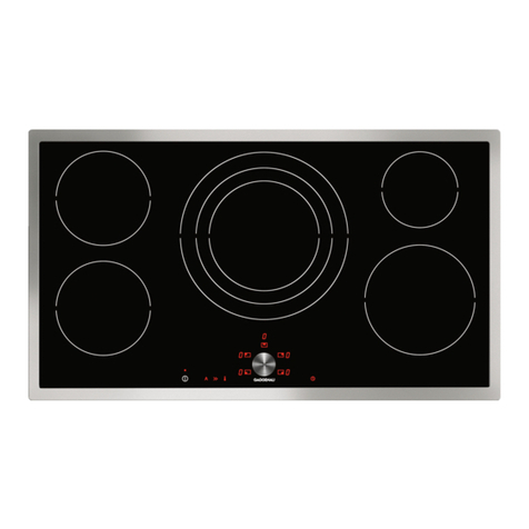
Gaggenau CX 491 User manual

Other Gaggenau Cooktop manuals

Gaggenau VI 414 613 User manual

Gaggenau

Gaggenau VI 414 613 User manual

Gaggenau VG 233 234 CN User manual

Gaggenau

Gaggenau VG 233 234 CN User manual

Gaggenau VP 230 620 User manual

Gaggenau

Gaggenau VP 230 620 User manual

Gaggenau CE 273 612 User manual

Gaggenau

Gaggenau CE 273 612 User manual

Gaggenau VI424 User manual

Gaggenau

Gaggenau VI424 User manual

Gaggenau VG 231 334 SG User manual

Gaggenau

Gaggenau VG 231 334 SG User manual

Gaggenau Vario 400 Series User manual

Gaggenau

Gaggenau Vario 400 Series User manual

Gaggenau VP 414 611 User manual

Gaggenau

Gaggenau VP 414 611 User manual

Gaggenau VG 442 User manual

Gaggenau

Gaggenau VG 442 User manual

Gaggenau CX 492 611 User manual

Gaggenau

Gaggenau CX 492 611 User manual

Gaggenau CI 282 601 User manual

Gaggenau

Gaggenau CI 282 601 User manual

Gaggenau VG 295 150 CA User manual

Gaggenau

Gaggenau VG 295 150 CA User manual

Gaggenau VI 411611 User manual

Gaggenau

Gaggenau VI 411611 User manual

Gaggenau VI 424 610 User manual

Gaggenau

Gaggenau VI 424 610 User manual

Gaggenau CI 292 610 User manual

Gaggenau

Gaggenau CI 292 610 User manual

Gaggenau CE291 Series User manual

Gaggenau

Gaggenau CE291 Series User manual

Gaggenau CI 282 610 User manual

Gaggenau

Gaggenau CI 282 610 User manual

Gaggenau VV 200-000 User manual

Gaggenau

Gaggenau VV 200-000 User manual

Gaggenau GE273 User manual

Gaggenau

Gaggenau GE273 User manual

Gaggenau CX 482 User manual

Gaggenau

Gaggenau CX 482 User manual

Gaggenau VG 295.20 User manual

Gaggenau

Gaggenau VG 295.20 User manual

Gaggenau VG491211CA User manual

Gaggenau

Gaggenau VG491211CA User manual

Gaggenau VI462105 User manual

Gaggenau

Gaggenau VI462105 User manual

Gaggenau VE 230 Manual

Gaggenau

Gaggenau VE 230 Manual

Popular Cooktop manuals by other brands

Fisher & Paykel CE302CBX2 manual

Fisher & Paykel

Fisher & Paykel CE302CBX2 manual

Whirlpool GJC3634RB00 parts list

Whirlpool

Whirlpool GJC3634RB00 parts list

Whirlpool ACH7324/BLV Use, care and installation guide

Whirlpool

Whirlpool ACH7324/BLV Use, care and installation guide

Frigidaire Professional FPDF4085KF Important safety instructions

Frigidaire

Frigidaire Professional FPDF4085KF Important safety instructions

Bonnet OPTIMUM 700 Technical instructions

Bonnet

Bonnet OPTIMUM 700 Technical instructions

Jenn-Air JGCP430 installation instructions

Jenn-Air

Jenn-Air JGCP430 installation instructions

Bompani BO374AA/E User instructions

Bompani

Bompani BO374AA/E User instructions

Kleenmaid cooking GCTK9011 Instructions for use and warranty details

Kleenmaid

Kleenmaid cooking GCTK9011 Instructions for use and warranty details

Waldorf RN8603E-B Technical data sheet

Waldorf

Waldorf RN8603E-B Technical data sheet

Whirlpool SMP658CNEIXL quick guide

Whirlpool

Whirlpool SMP658CNEIXL quick guide

Electrolux E36IC80ISS - 36" Induction Cooktop Wiring diagram

Electrolux

Electrolux E36IC80ISS - 36" Induction Cooktop Wiring diagram

Wolf CI243C/B Use and care guide

Wolf

Wolf CI243C/B Use and care guide

Fulgor Milano F5PGK305S1 installation instructions

Fulgor Milano

Fulgor Milano F5PGK305S1 installation instructions

Wells WV-2HFG owner's manual

Wells

Wells WV-2HFG owner's manual

Samsung NA36N9755 installation manual

Samsung

Samsung NA36N9755 installation manual

Miele KM 404 operating instructions

Miele

Miele KM 404 operating instructions

Lacor 69562 Instructions for use and maintenance

Lacor

Lacor 69562 Instructions for use and maintenance

Keating Of Chicago MG-2 manual

Keating Of Chicago

Keating Of Chicago MG-2 manual

manuals.online logo
manuals.online logoBrands
  • About & Mission
  • Contact us
  • Privacy Policy
  • Terms and Conditions

Copyright 2025 Manuals.Online. All Rights Reserved.

CX 491 610
Stainless steel frame
Width 36" (90 cm)
Installation accessories
In combination of several Vario
cooktops, connecting strips must be
used.
Choose respective VA 420 strip from
one of the below, depending on type
of installation.
VA 420 010
Connection strip for surface-mount
installation without appliance cover.
VA 420 011
Connection strip for surface-mount
installation with appliance cover.
VA 420 000
Connection strip for flush installation
without appliance cover.
VA 420 001
Connection strip for flush installation
with appliance cover.
VA 450 900
36" stainless steel adjustment strip.
Necessary accessory in a combina-
tion of 15" Vario(s) with at least one
cover adjacent to a 36" cooktop. VA
450 strip will compensate the
appliance depth.
Optional accessories
GN 232 110
Teppan Yaki plate made of multi-ply
material, 13" x 21".
GN 232 230
Teppan Yaki plate made of multi-ply
material, 13" x 14.
GN 340 230
Gastronorm roaster
Non-stick cast-aluminum
4" deep, with 2 ½" lid, GN ⅔
GP 900 001
Stainless steel 6" frying pan
Non-stick cooking.
GP 900 003
Stainless steel 8" frying pan
Non-stick coating.
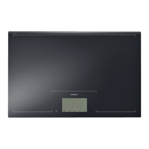
Full surface induction cooktop
CX 491
– One large cooking surface
– Free positioning of cookware
– Cookware of any shape and size
can be used
– TFT touch display for an intuitive
control of all functions
– Max. power output for large
cookware of up to 4,600 W with
Power boost function
– Precision-crafted ⅛-inch stainless
steel frame
– For surface-mount installation with
a visible edge or for flush
installation
– Can be perfectly combined with
other Vario 400 series products
Cooking zones
One unique cooking surface allows for
cookware as small as 3" and as large
as 13" x 21".
Up to 4 items of cookware can be
placed simultaneously on the cooktop.
Operation
Large 6.5" color graphic TFT touch
display with an easy-to-use display
concept.
Electronic power control in 17
output levels.
Features
Power boost function.
Individual pot detection.
Timer for each cooking position.
Short-term timer.
Information key with use indicators.
Power management.
Safety
Main switch.
Residual heat indicator.
Child lock.
Display cleaning protection.
Planning notes
Depending on the type of installation
(surface-mounted or flush-mounted),
the specific definition of the cut-out
must be observed.
When using the appliance cover
VA 440 or adjustment strip VA450
additional space for cut-out depth
needs to be considered.
In a combination of Vario cooktops
with at least one appliance cover, the
adjustment strip VA 450 is required.
In a combination of several Vario 400
series cooktops a connection strip
must be used.
Depending on the type of installation—
surface- or flush-mounted, with or
without cover — the respective VA 420
connecting strip must be used.
For flush installation the edge height
in the cut-out needs to be at least ½"
and for surface-mount ⅜". Ensure a
continuous cut surface of 90°.
The weight capacity and stability,
especially in case of thin countertops,
must be supported using suitable
substructures. Take the appliance
weight and additional loads into
account.
Flush installation is possible in
countertops made of stone, synthetics
or solid wood. Heat resistance and
watertight sealing of the edges must
be observed. For other materials,
please consult with your countertop
manufacturer.
The groove must be continuous and
even, so that uniform placing of the
appliance on the gasket is ensured.
Do not use discontinuous lining.
Operates with magnetic (induction)
iron pots and pans only. For an optimal
heat distribution, the use of sandwich
bottom cookware is recommended.
Immersion depth depending on
installation situation, 3 ³⁄₁₆" for surface-
mount or 3 ⁵⁄₁₆" for flush-mount.
Intermediate shelf is required.
Appliance can be snapped into the
countertop from above.
Please read additional planning notes
on combinations with Vario 400 series
cooktops on pages 82 – 87.
Please read the installation details
regarding air ducting on page 121.
Rating
Total rating: 7.2 kW.
Total Amps: 40 A.
208/220–240 V / 60 Hz
Plan for a 37" connecting cable
without plug (hardwire required).
Numbers indicated
inside parenthesis ( ) = mm
min. 2"
(50)
min.
23
5
/
8
"
(600)
min.
1
3
/
8
"
(35)
min.
7
/
8
"
(20)
R
1
/
8
" (R
3)
90°
*
with adjustment strip. See separate planning notes.
**
Recessed depth in the vicinity of the electrical
connection box: 4
1
/
16
" (104).
1
9
3
/
8
"
±
1
/
16
(492
±2
)
*20
1
/
4
"
+
1
/
16
(*515
+2
)
34
15
/
16
"
±
1
/
16
(887
±2
)
**3
1
/
6
"
(**81)
1
/
8
"
(3)
20
1
/
2
" (520)
*
21
1
/
16
" (*535)
35
3
/
4
"
(908)
4
3
/
8
" (110)
35
1
/
2
"
(900)
min. 2"
(50)
min.
1
3
/
16
"
(30)
90°
R
3
/
16
"
(R5)
min. 23
5
/
8
"
(600)
*
with adjustment strip. See separate planning notes.
**
Recessed depth in the vicinity of the electrical
connection box: 4
2
/
7
" (107).
1
/
8
"
(3.5
-0.5
)
20
11
/
16
"
+
1
/
16
(526
+2
)
*21
1
/
4
"
+
1
/
16
(*541
+2
)
36"
+
1
/
16
(914
+2
)
1
/
8
"
(3)
35
3
/
4
"
(908)
4
3
/
8
" (110)
35
1
/
2
"
(900)
**3
2
/
7
"
(**84)
34
15
/
16
"
±
1
/
16
(887
±2
)
20
1
/
2
" (520)
*
21
1
/
16
" (*535)
1
9
3
/
8
"
±
1
/
16
(492
±2
)
*20
1
/
4
"
+
1
/
16
(*515
+2
)
Surface-mount Installation Flush-mount Installation
* with adjustment strip
View from above
R
3
/
16
"
(5
+1
)
R
1
/
8
"
(3)
36"
+1
/
16
"
(914
+2
)
34
15
/
16
"
±1
/
16
"
(887
±2
)
19
3
/
8
"
±1
/
16
" (
492
±2
)
*20
1
/
4
"
+1
/
16
"
(*515
+2
)
20
11
/
16
"
+1
/
16
" (
526
+2
)
*
21
1
/
4
"
+1
/
16
"
(*541
+2
)
View from above
fill with
silicone
Longitudinal section
1
/
8
" (3.5
-0.5
)
17
/
32
"
(13.5)
17
/
32
"
(13.5)
34
15
/
16
"
±1
/
16
"
(887
±2
)
36"
+1
/
16
"
(
914
+2
)
35
3
/
4
" (908)
1
/
8
"
(3
+1
)
1
/
8
"
(3
+1
)
Longitudinal section
When installating with appliance cover or adjustment strip, pay attention
to the deeper cut-out and the front and rear groove width.
Cross-section
fill with
silicone
1
/
8
" (
3.5
-0.5
)
19
3
/
8
"
±1
/
16
"
(492
±2
)
20
11
/
16
"
+1
/
16
"
(526
+2
)
11
/
16
"
(17)
11
/
16
"
(17)
1
/
8
"
(3
+1
)
1
/
8
"
(3
+1
)
20
1
/
2
"
(520)
Cross-section
* with adjustment strip. See separate planning notes on page 87.
** Recessed depth in the vicinity of the electrical connection box: 4 ¹⁄₁₆".
* with adjustment strip. See separate planning notes on page 87.
** Recessed depth in the vicinity of the electrical connection box: 4 ²⁄₇".