manuals.online logo
Brands
  1. Home
  2. •
  3. Brands
  4. •
  5. Gaggenau
  6. •
  7. Ventilation Hood
  8. •
  9. Gaggenau VL040-707 Product guide

Gaggenau VL040-707 Product guide

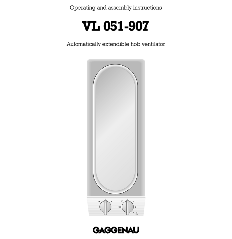
Operating and assembly instructions
VL 040/041-707
Hob ventilator
0
1
2
VL 040/041-707
1
Preface
Safety notes Page 3
1. Important notes Page 4-5
1.1 For your safety Page 4
1.2 Operating for the first time Page 5
2. Structure and operating principle Page
2.1 Structure of the appliance Page
2.2 Accessories Page
3. Operation Page 7
4. Cleaning and care Page 8
5. Maintenance Page 8
2
Preface
With your new hob ventilator, working in the
kitchen will be even more fun.
The appliance offers you the following
advantages:
– Kitchen vapours and fats are sucked away
directly where they arise.
– One-hand operation ensures high operating
convenience.
To ensure that you will be able to use this
appliance in all its diversity, read through
the operating and assembly instructions
conscientiously before operating it for the
first time. The instructions contain important
notes on use, installation and maintenance of
the appliance.
On the following page you will find important
notes on safety and operation. These will serve
to ensure your personal safety and the lasting
value of your appliance.
You will find notes on Page 3 that you ought to
observe before operating the appliance for
the first time.
Tips and hints in the chapter entitled "Cleaning
and care" will make sure that your appliance will
stay operable and beautiful for a long time.
nd now we wish you lots of fun with your
new hob ventilator.
2
Fig. 2
Fig. 1
VL 041-707
VL 040-707
W RNING - TO REDUCE THE RISK OF FIRE,
ELECTRIC SHOCK, OR INJURY TO PERSONS,
OBSERVE THE FOLLOWING:
a.) Use this unit only in the manner intended by the
manufacturer. If you have questions, contact
the manufacturer.
b.) Before servicing or cleaning unit, switch power
off at service panel and lock the service
disconnecting means to prevent power from
being switched on accidentally. When the
service disconnecting means cannot be locked,
securely fasten a prominent warning device,
such as a tag, to the service panel.
C UTION:
FOR GENERAL VENTILATION USE ONLY. DO NOT
USE TO EXHAUST HAZARDOUS OR EXPLOSIVE
MATERIALS AND VAPORS.
W RNING - TO REDUCE THE RISK OF
R NGE TOP GRE SE FIRE.
a.) Never leave surface units unattended at high
settings. Boilovers cause smoking and greasy
spillovers that may ignite. Heat oils slowly on low
or medium settings.
b.) Always turn hood ON when cooking at high heat
or when cooking flaming foods.
c.) Clean ventilating fans frequently. Grease should
not be allowed to accumulate on fan or filter.
d.) Use proper pan size. Always use cookware
appropriate for the size of the surface element.
W RNING - TO REDUCE THE RISK OF INJURY
TO PERSONS IN THE EVENT OF R NGE
TOP GRE SE FIRE, OBSERVE THE
FOLLOWING:
a.) SMOTHER FLAMES with a close-fitting lid,
cookie sheet, or metal tray, then turn off the
burner. BE CAREFUL TO PREVENT BURNS. If the
flames do not go out immediately, EVACUATE
AND CALL THE FIRE DEPARTMENT.
b.) NEVER PICK UP A FLAMING PAN - You may be
burned.
c.) DO NOT USE WATER, including wet dishcloth or
towels - a violent steam explosion will result.
d.) Use an extinguisher ONLY if:
1. You know you have Class ABC extinguisher,
and you already know how to operate it.
2. The fire is small and contained in the area
where it started.
3. The fire department is being called.
4. You can fight the fire with your back to an exit.
Safety notes
3
Read nd Save These Instructions.
4
1. Important notes
1.1 For your safety
Damaged appliances must not be operated.
The appliance must only be connected by an
authorised specialist, paying attention to the
relevant regulations of the power supply companies
and the regional construction regulations.
lso observe the assembly instructions!
Connecting cables must not come into contact
with hot cooking surfaces.
Hazardous or explosive substances and vapours
must not be extracted!
The user is responsible for expert use and the
perfect condition of the appliance.
Never operate the appliance without a grease
filter.
Only ever operate the appliance under
supervision. The appliance is intended solely for
use in the household and must not be put to any
other uses.
Caution! Over-greased filters are a fire risk! Only
ever deep-fry next to the appliance under constant
supervision. Pay attention to cleaning the grease
filter on a regular basis.
Do not clean the appliance with a steam cleaning
apparatus or with water pressure because this
poses a risk of short-circuits.
Isolate the appliance from the mains during every
maintenance operation. To do this, remove the
mains plug or actuate the corresponding fuse. If the
mains plug is not accessible, the appliance must be
deenergised by means of the domestic installation
fuse.
In the event of malfunctions, first of all check
the household fuses. If the malfunction has nothing
to do with the power supply, please contact your
specialist dealer or your responsible Gaggenau
after-sales service. Repairs must be carried out by
authorised specialists, thus ensuring electrical
safety.
No warranty claims can be lodged in the event
of damage caused by failure to observe these
instructions.
Fire risk! It is not permitted to flambé meals next
to a hob ventilator that is in operation.
If you have installed the hob extractors VL 040/041
next to a gas appliance, each has to be fitted with
an air baffle LS 041 while cooking. The air baffle not
only improves the air flow of the extractor next to a
gas appliance, but also prevents a flame which has
been set to a low level from being extinguished.
You may only ever use a grill or a deep fryer at
the same time as the hob ventilator if it is under
constant supervision.
This will involve a fire risk!
Do not place any objects on the appliance; this
will have a detrimental effect on functioning.
Technical modifications reserved.
5
1.2 Operating for the first time
Before operating the appliance for the first time,
please pay attention to the following notes:
– Conscientiously read through the operating
and assembly instructions before operating the
appliance for the first time.
– The rating plate for this appliance is included
with the instructions on a separate sheet. Store
the rating plate in the same location as your
operating and assembly instructions. You need
the rating plate for possible damage and warranty
cases.
– Remove the packaging from the appliance and
dispose of it properly. Pay attention to the fact that
there are accessories in the packaging.
Keep packaging elements out of the reach of
children!
–Thoroughly clean the appliance before using it
for the first time. (see chapter entitled "Cleaning
and care")
–Before operating the appliance for the first
time, check that the mains connection is in proper
working order.
2.1 Structure of the appliance
2.2 ccessories
1Ventilation grille
2Control knob (VL 041-707 only)
3Clamping screw
4Retaining bracket
5Suction extraction connection
Special accessories:
S 070-000: connection piece for extension during
assembly (fig. 4)
VV 200-000: connecting trim
RV 050-150: bifurcated pipe for joining 2 x DN 125
into DN 150 (fig. 5)
LS 041-000: air baffle
2. Structure and operating principle
2
1
2
3
4
5
Fig. 3
Fig. 4
Fig. 5
7
Switching on
Switching off
Note:
VL 040 can only be operated in combination with
VL 041 or VL 051. All operator inputs apply to both
hob ventilators. That is to say: if you set the control
knob to level 1, both hob ventilators are operated
at level 1.
Switching on
Turn the control knob to the right to the position you
require (0-2).
Switching off
Turn the control knob to the left to the 0 position.
3. Operation
Fig.
Fig. 7
8
Caution:
Avoid sharp and caustic cleaning agents as well as
brushes and abrasive cleaners.
The stainless steel frontages must only be
cleaned with a soft cloth.
Do not use any abrasive sponges either. Use
commercially available window cleaner and apply it
to a soft, moist cloth. Do not spray it onto the switch
panel.
Clean the ventilation grille with a moist cloth
and detergent solution. You should not clean the
ventilation grille in a dishwasher because spots
may appear on the ventilation grille.
Grease filter cleaning
You can clean the metal grease filters in a
dishwasher at a maximum temperature of 5°C /
150 °F. Place the grease filter in the dishwasher with
the opening pointing down to ensure that no food
remainders will stay on it.
Proceed as follows: (fig. 8)
– Detach the ventilation grille.
– Turn up the two retaining wires and detach the
grease filter from the appliance.
Insert in the reverse order.
The appliance must be disconnected from the
power supply during all repair work.
If the appliance does not function correctly, check
the fuses first.
If the power supply is functioning correctly, but your
appliance still does not work, please contact your
Gaggenau dealer who will provide you with the
address and telephone number of your nearest
manufacturer’s authorized service agent or contact
Gaggenau US on (800) 828-9165. Specify the
appliance type (see rating plate).
4. Cleaning and care
5. Maintenance
2
Repairs must only be carried out by authorised
specialists, thus ensuring the safety of the
appliance. Improper tampering will render all
warranty claims null and void.
Fig. 8
The grease filters must be cleaned on a regular
basis (at the latest after 30 hours of operation).
Overgreased filters are a fire risk!
9
6.1 Technical data
Rating: 120V 0Hz
Weight: 3.9 kg
Power consumption with GB 031: 250W
Technical modifications reserved.
6.2 How to do it
W RNING - TO REDUCE THE RISK OF FIRE,
ELECTRIC SHOCK, OR INJURY TO PERSONS,
OBSERVE THE FOLLOWING:
a.) Installation work and electrical wiring must be
done by qualified person(s) in accordance with
all applicable codes and standards, including
fire-rated construction.
b.) Sufficient air is needed for proper combustion
end exhausting of gases through the flue
(chimney) of fuel burning equipment to prevent
back drafting. Follow the heating equipment
manufacturer’s guideline and safety standards
such as those published by the National Fire
Protection Association (NFPA), and the American
Society for Heating, Refrigeration and Air
Conditioning (ASHRAE), and the local code
authorities.
c.) When cutting or drilling into wall or ceiling, do
not damage electrical wiring and other hidden
utilities.
d.) Ducted fans must always be vented to the
outdoors.
e.) If this unit is to be installed over a tub or shower,
it must be marked as appropriate for the appli-
cation and be connected to a GFCI (Ground
Fault Circuit Interrupter) - protected branch
circuit.
f.) NEVER place a switch where it can be reached
from a tub or shower.
W RNING:
To reduce the risk of fire, use only metal ductwork.
. Assembly instructions
VL 041-707 /01 FD xxxx xxxxxx
AC 120V / 0Hz max 500W 2.2A
The appliance must only be connected by
an authorised specialist. The specialist is
responsible for perfect functioning of the appliance
at its installation location. He must explain the
operating principle of the appliance to the user with
reference to the operating instructions. He must
explain to the user how the appliance can be
isolated from the mains whenever required.
The exhaust air can be routed into a ventilation
shaft or directly into the open through the outside
wall. Adequate incoming air must be ensured
whenever the hob ventilator is operated in the
exhaust air mode and firing systems dependent
on a chimney are operated at the same time.
It is not allowed to pass the exhaust air into a flue
or exhaust air chimney that is in operation or into a
shaft that is linked to the heating basement. Consult
the chimney sweep responsible for your district
whenever you wish to pass the exhaust air into a
chimney that is not in operation.
dequate incoming air must be ensured if a
wood, coal, gas or oil heater or an open hearth is
operated in the same room as the one in which
the wall hood is installed.
dequate ventilation of the room must be
ensured whenever a hob ventilator is operated
simultaneously with devices that are operated with
non-electrical energy. Official regulations must be
observed with regard to removal of the exhaust air.
The applicable regulations of the power
supply companies and the regional construction
regulations must be observed when installing the
hob ventilator.
The lateral distance from the appliance installed
next to it must amount to 8 mm.
Safe operation is possible whenever the partial
vacuum in the place where the firing equipment is
installed does not exceed 4 Pa (0.04 mbar). This
can be achieved whenever the air needed for
combustion is able to enter through openings that
cannot be sealed, for example in doors, windows,
incoming/exhaust air wall boxes or other technical
means.
Flexible aluminium pipes, corrosion-protected
sheet metal pipes and exhaust air pipes whose
material conforms to fire B1 in accordance with
DIN 4102 can be used. Exhaust air pipes should
have a nominal diameter of 125 mm.
fter installation, plug the connecting cable plug
in an accessible socket. If the plug can no longer be
removed after installation, isolation of all poles from
the mains must be ensured by means of an acces-
sible isolator with a contact spacing of at least 3 mm.
If two Vario appliances are used, the hob
ventilator must be installed between the
appliances. If 4-plate hobs are used, it is
recommended to place two ventilation devices to
the left and right of the hob. Owing to the high air
output, an adequate supply of air is required.
If you have installed the hob extractors VL 040/041
next to a gas appliance, each has to be fitted with
an air baffle LS 041 while cooking.
To prevent the ingress of water, e.g. condensate
or rain water from an uncovered exhaust air shaft,
our condensate separator RV 050-150 must be
installed in the proximity of the hob ventilator. The
condensate separator must still be accessible after
installation.
Electrical connection
Pay attention to the rating plate data.
If damaged, the mains cable must be replaced by a
special mains connecting cable. The mains connec-
ting cable must only be connected by the manu-
facturer or the manufacturer's after-sales service.
When connecting the power supply cord to the
receptacle located below the cooktop surface, the
cord is to be:
– Routed beneath the appliance; and
– Routed away from heat generated by the cooktop.
10
11
Installation
Proceed as follows:
– Produce the recess for the appliance. Proceed
as indicated on the installation sketch and the
dimension table (fig. 9). Important: the angle
between the cut surface and the worktop must
amount to 90°.
– Install the hob ventilator as the first appliance.
Only then install Vario appliances in accordance
with the assembly instructions.
– As standard, the blow-out direction is downward.
Proceed as follows to establish a blow-out
opening at the side:
– Undo all 5 screws on the connection piece and
detach the connection piece.
– Undo the screws of the side cover.
– Screw the connection piece onto the side
opening and the cover onto the bottom opening.
– Mark the centre of the recess exactly. Secure
the securing rail in the rear recess (fig. 10). Make
sure that the contact face of the securing rail lies
on the worktop and that the centre marking of the
securing rail is precisely flush with the centre
marking on the worktop.
14
3
/
8
"
Fig. 9
Fig. 10
12
– Lower the appliance into the worktop. Make
sure that the engaging lugs on the appliance
lie exactly on the clamping springs. Press the
appliance firmly into the worktop. The engaging
lugs on the appliance "snap" into the clamping
springs.
– Screw the included screw from below into the
hooked-in retaining bracket (fig. 11). Fit the cap
onto the top of the screw.
– Fully screw in the screw.
– Connect the hob ventilator to the fan module by
means of the 4-pole plug.
Pay particular attention to ensuring that
– the exhaust air ducts are kept as short as possible
– the pipes are not laid at an acute angle, but as
bends and that they are inserted into the shaft at
an inclined upward angle and
– there are no cross-sectional constrictions in the
upward direction (this reduces the volume flow).
We recommend the use of our telescopic wall box
TM 180-043 to route exhaust air through the outside
wall.
2
Fig. 11
3. 027.93ind02 en 03.03 SK 13
5551 McFADDEN AVENUE
HUNTINGTON BEACH, CA 92649
USA
Y(800) 828-9165 · FA (714) 901-0979
www.gaggenau-usa.com
GAGGENAU HAUSGERÄTE GMBH
P.O. BO 10 02 50 · 80076 MÜNCHEN
GERMANY
Y(089) 45 90-03
FA (089) 45 90-23 47

Other manuals for VL040-707

1

This manual suits for next models

1

Other Gaggenau Ventilation Hood manuals

Gaggenau AF210162 User manual

Gaggenau

Gaggenau AF210162 User manual

Gaggenau VL 200 120 User manual

Gaggenau

Gaggenau VL 200 120 User manual

Gaggenau AW250192 User manual

Gaggenau

Gaggenau AW250192 User manual

Gaggenau AT 400-700 User manual

Gaggenau

Gaggenau AT 400-700 User manual

Gaggenau AH600790 Product guide

Gaggenau

Gaggenau AH600790 Product guide

Gaggenau AC 200 User manual

Gaggenau

Gaggenau AC 200 User manual

Gaggenau AT 400-730 User manual

Gaggenau

Gaggenau AT 400-730 User manual

Gaggenau AW240120 User manual

Gaggenau

Gaggenau AW240120 User manual

Gaggenau AI 540-720 Product guide

Gaggenau

Gaggenau AI 540-720 Product guide

Gaggenau VL 410 User manual

Gaggenau

Gaggenau VL 410 User manual

Gaggenau AC2001.1 User manual

Gaggenau

Gaggenau AC2001.1 User manual

Gaggenau AW24.120 User manual

Gaggenau

Gaggenau AW24.120 User manual

Gaggenau AW 260-170 Assembly instructions

Gaggenau

Gaggenau AW 260-170 Assembly instructions

Gaggenau VL 414 User manual

Gaggenau

Gaggenau VL 414 User manual

Gaggenau AC 250 User manual

Gaggenau

Gaggenau AC 250 User manual

Gaggenau AH 600 Product guide

Gaggenau

Gaggenau AH 600 Product guide

Gaggenau AI201102 Product guide

Gaggenau

Gaggenau AI201102 Product guide

Gaggenau AT 400 User manual

Gaggenau

Gaggenau AT 400 User manual

Gaggenau AC 250 User manual

Gaggenau

Gaggenau AC 250 User manual

Gaggenau AW 400190 User manual

Gaggenau

Gaggenau AW 400190 User manual

Gaggenau AW 202 Product guide

Gaggenau

Gaggenau AW 202 Product guide

Gaggenau AI540122 Product guide

Gaggenau

Gaggenau AI540122 Product guide

Gaggenau VL 040 714 User manual

Gaggenau

Gaggenau VL 040 714 User manual

Gaggenau AH 590-720 Product guide

Gaggenau

Gaggenau AH 590-720 Product guide

Popular Ventilation Hood manuals by other brands

AGA ARAFX30W5SS Instruction booklet

AGA

AGA ARAFX30W5SS Instruction booklet

Electrolux EFC 650-950 user manual

Electrolux

Electrolux EFC 650-950 user manual

Perfelli DNS 6723 B 1100 LED Strip user manual

Perfelli

Perfelli DNS 6723 B 1100 LED Strip user manual

Schweigen DS3131S installation guide

Schweigen

Schweigen DS3131S installation guide

Miele DA 420 V EXT Operating and installation instructions

Miele

Miele DA 420 V EXT Operating and installation instructions

Smeg IS280 Installation and operating instructions

Smeg

Smeg IS280 Installation and operating instructions

Everdure RBBQ120S Installation operation & maintenance

Everdure

Everdure RBBQ120S Installation operation & maintenance

Yale RH10836AS Use, care and installation guide

Yale

Yale RH10836AS Use, care and installation guide

AEG DGK6681HM user manual

AEG

AEG DGK6681HM user manual

GE JV356 30 Use and installation guide

GE

GE JV356 30 Use and installation guide

Electrolux EFG60750X user manual

Electrolux

Electrolux EFG60750X user manual

EAS Electric EMRH604X instruction manual

EAS Electric

EAS Electric EMRH604X instruction manual

Novy 810 manual

Novy

Novy 810 manual

Bosch I92C67N0 installation instructions

Bosch

Bosch I92C67N0 installation instructions

AEG DI 8820 Operating and installation instructions

AEG

AEG DI 8820 Operating and installation instructions

Candy CFT63/1W/1 instruction manual

Candy

Candy CFT63/1W/1 instruction manual

ELICA EGS436SS Use, care and installation guide

ELICA

ELICA EGS436SS Use, care and installation guide

Presenza QR015 Installation guide and user's manual

Presenza

Presenza QR015 Installation guide and user's manual

manuals.online logo
manuals.online logoBrands
  • About & Mission
  • Contact us
  • Privacy Policy
  • Terms and Conditions

Copyright 2025 Manuals.Online. All Rights Reserved.