GALA VIKING V Series User manual


GALA inflatable boats
Series V – VIKING
V330, V360, V420
User’s Manual
CONTENTS Page
Part 1. Specifications and assembling
1. Models and specification 2
2. Standard features and optional equipment 2
3. Boat views 3
4. Boat assembling 4
5. Valves operation 5
6. Electric system 6
7. Fuel system 7
Part 2. Safety and precautions
8. Recommendation signs 8
9. An important message 8
10. Certification 9
11. Identification 9
12. Manufacturer's ID plate 9
13. Motor type, installation and operating 11
14. Boat operating instructions: 13
a. Distribution of the load 13
b. Checklist before departing 13
c. Rules to observe during navigation 14
d. Moring and towing 15
e. Lifting 15
f. Trailer 15
15. In case of accident 16
16. Environment 16
17. Maintenance: 17
a. Cleaning 18
b. Air tightness of inflatable tube 18
c. Maintenance of stainless steel 18
d. Maintenance of the aluminium and plywood seats and floor 18
e. Winterizing and storage 18
18. Contacts and Service 18

PART 1. SPECIFICATIONS AND ASSEMBLING
1. MODELS AND SPECIFICATIONS
VIKING V330, V360 are RIB models with aluminium hull and remote steering, including
steering console and integral rear seat.
Models
V330
V360
V
42
0
Length overall cm
ft/inches
330
10’ 10”
360
11’ 10”
420
13’ 9”
Width overall cm
ft/inches
177
5’ 8”
186
6’ 1”
192
6’ 4”
Tube diameter max
cm
ft/inches
44
17”
48
19”
48
19”
Bare boat weight kg
lbs
125
275
150
330
222
488
Loading capacity kg
lbs
500
1100
700
1540
850
1870
Passengers capacity
5
6
7
No of chambers
3
3
4
Engine power max HP
kW
30
22.1
40
29.4
60
44.1
Engine weight max kg
lbs
80
176
100
220
120
2
64
Engine shaft length inches 20”
(long)
20”
(long)
20”
(long)
Design category
C
C
C
All technical data are subject to change without notice. The products details and specifications may be changed from
specified herein. All the dimensions are + or - 3%. All the weights are + or - 10%

2. STANDARD FEATURES AND OPTIONAL EQUIPMENT
STANDARD FEATURES:
Medium “V” powder-coated aluminium self- bailing hull with «GALA TABS», motor
well, rear splash deflectors, keel protector, zinc anode.
Steering console with windshield and railing
Rear compartment with motor well, rear storage with soft seat and two back supports
Steering system with steering wheel and cable
Bow locker with hatch and soft cushion
4 lifting eyes and 3 towing bow eyes
Bow handle
Two rear GALA cleats
8 safety grab handles
Soft curved 3 (V330, V360) /4 (V420) -chamber VALMEX / Hypalon buoyancy tube
with rounded bow
Overpressure valve
Tough rubbing strake with splash guard
One-way drain valve with plug
Two paddles
High-efficiency foot pump
Repair kit and manual
OPTIONAL EQUIPMENT:
Bow step plate with cleat, soft seat back and anchor roller (V360, V420)
Electric package (incl. nav. lights, bilge pump, horn, battery switch etc)
Two side step panels
Fuel system with 40 lit tank (V330, V360), 83 lit (V420)
SEADECK decking
Overall cover
Console cover

3. BOAT VIEWS
VIKING V330, V360 general view (with some options):
VIKING V420 general view (with some options):

4. BOAT ASSEMBLING
Step 1: Open the boat
- Inspect the condition of the package for and report to your dealer if you find any
damages.
- Remove all the packaging plastic and cardboard carefully. Do not use knife.
- Check the completeness of the boat and make sure that no any parts are missing. You
must report the missing part to your dealer immediately.
Step 2: Assemble and install steering console
Unpack the steering console. Connect and secure the steering cable to the steering
system. Install steering wheel. If your boat is expected to feature electric start – install the
battery tray on the deck under steering console. Assemble and mount control box on the
right side of the console. Make sure the handle in upper position does not touch the railing.
Install the steering console on the deck with bolts with washers and tighten them.
Step 3: Install outboard motor
Install the outboard motor following the motor user’s manual.
Step 4: Install two rear seat backs
Unpack the two rear seat backs and install them on the hull with bolts with washers and
tighten them.
Step 5: Inflate the boat
- Open the pump, connect the pump hose to the pump onto inflation opening.
- Connect bayonet adapter of the pump hose to the valve
- Inflate the rear compartments first up to pressure slightly below nominal, and the bow
compartment the last up to the nominal pressure.
In this case the flexible baffles in the tube will move towards the rear compartments and
equalize the pressure in all compartments. You may use the manometer to measure the
pressure level to ensure the best performance of the boat and make sure that the pressure
is about nominal level. Nominal tube pressure is mentioned on Capacity Plate.

IMPORTANT!!! WE STRONGLY RECOMMEND THE BOAT ASSEMBLING AND THE
OUTBOARD MOTOR RIGGING TO BE MANAGED BY CERTIFIED BOAT DEALER
ONLY.
5. VALVES OPERATION
INFLATION-DEFLATION VALVE operation:
Inflation-deflation valve has PUSHPUSH operating system: pressing the central pin the
valve switches between OPEN and CLOSED. To inflate the tube put the pin to CLOSED
position (pin moves UP). To deflate the tube put the pin to OPEN position (pin moves
DOWN). After inflation every valve must be closed with the valve plug tight to ensure
airtightness of the tube.
OVERPRESSURE VALVE operation:
Overpressure valve protects the boat against unexpected pressure increase over the
maximum working limit. In case of any tube pressure increase or overinflating the gasket of
the valve will open automatically, release all excessive air and bring the tube pressure to
nominal. Make sure that the valve cup is always clean. Check the valve operation during
boat maintenance.

a) DRAIN VALVE operation:
Drain system includes: a) two drain through-hull fittings at the bottom of the rear
compartment wall with two expanding plugs, b) one way drain valves on the boat transom,
c) connecting tube. The cockpit of the boats is self bailing. To drain the water off the
cockpit, take out the expanding plugs and water will drain out automatically. For effective
draining inspect drain system regularly and make sure it is always clean, free of debris and
has no any damages.
WARNING
OVERINFLATING AND OVERHEATING OF YOUR BOAT MAY CAUSE THE BOAT
DAMAGE. AVOID OVERPUMPING THE BOAT, LEAVING THE BOAT NOT COVERED,
USING HIGH-PRESSURE INFLATORS. USE MANOMETER TO CHECK THE
PRESSURE IN THE TUBE REGULARLY.

6. ELECTRIC SYSTEM
GALA Viking electric system wiring diagram:
*GALA MARINE reserves the right to modify the boat wiring or wiring diagram without notice.
• All models come with manual bilge pump
• Fuel send wiring is presented only on the boats with fuel system installed,
• To connect the engine, follow the engine’s user manual instructions and rigging guide.
• Regularly inspect the condition of all electric elements and wiring, and clean or replace
elements with signs of corrosion or any damage
• Inspect the functionality of all system features before your ride
• To change the fuses, use only fuses with proper design and ratings
• Protect fuses and other elements of electric system from water
• Keep your battery disconnected with battery switch at all time when the boat is not in use.
• Maintain your battery following the battery user’s manual instructions.
• In case of smoke or insulation burning smell switch your battery off to avoid fire.
• Do not use any of electric equipment with a sign of its damage or non-proper functioning.
• Actual wiring may be modified from shown herein at factory choice
• Manufacturer does not allow modification of electric system without written consent.

7. FUEL SYSTEM
GALA boats fuel system is optional feature for V330, V360 and it includes:
Permanently installed fuel tank with 40 lit capacity.
STD type fuel sender (sender resistance 240-33 Ohm)
Gas fill with vent
Fill-in hose, vent hose, engine feeding hose traced to the boat transom
Fuel system does not include any fuel filters, gauges, or other equipment not listed above.
All additional equipment has to be installed and properly tested before use by qualified
Dealer or other company, which does the rigging of the boat to make sure that the fuel
system final installation and connections meet the local legal requirements and standards.
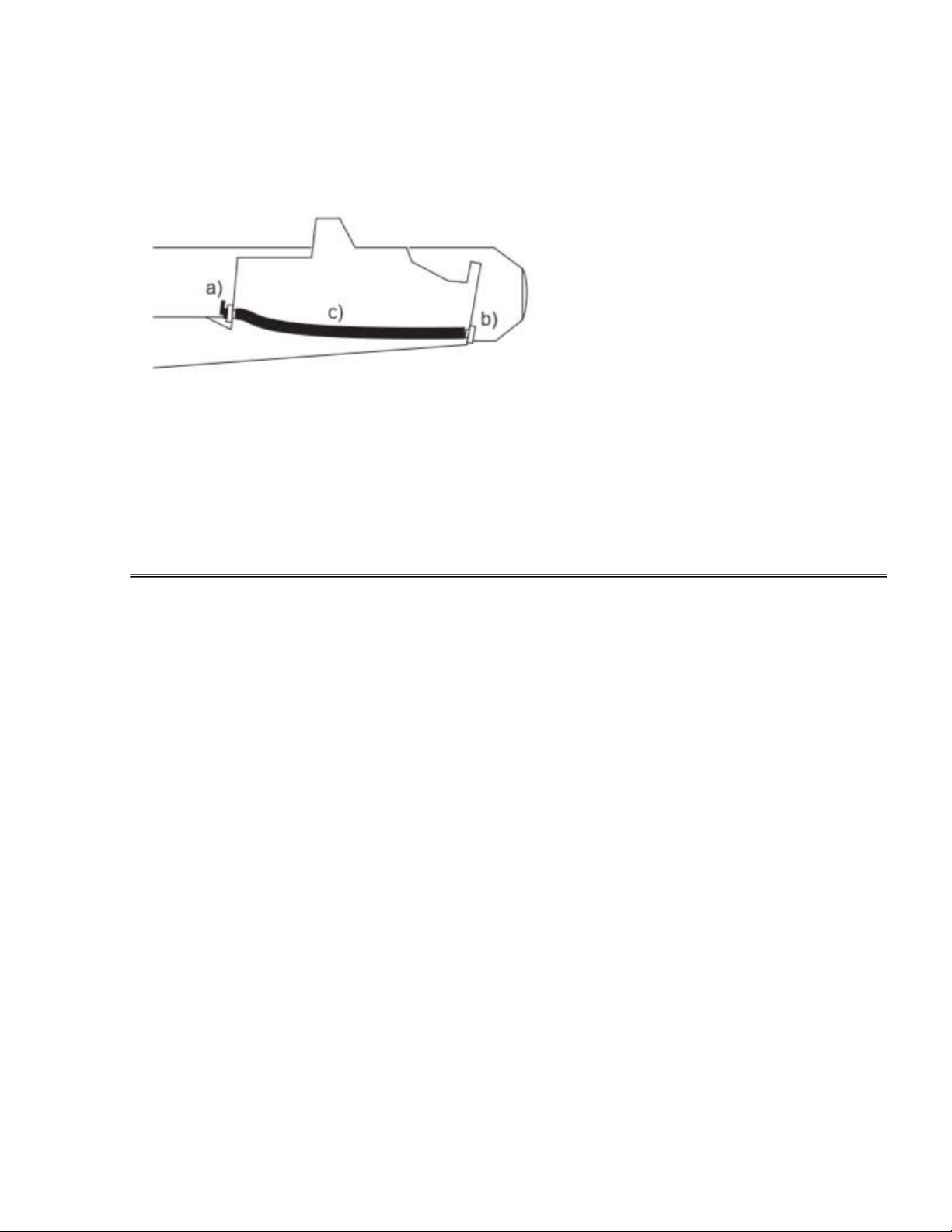
7.1. Fuel system mounting
Fuel tank is permanently installed in the rear compartment with deck fill located at the left
side of rear compartment. The tank is accessible for inspection through the rear locker
hatch.
V330, V360 fuel system: V420 fuel system:
7.2. Safety:
WARNING:
- Never overfill your fuel tank or spill fuel – spilling fuel into the engine or passenger
compartment can increase the risk of explosion or fire, and spilling fuel into water
will harm the marine environment.
- Never smoke while refueling, fuel system service or inspection
- The boat battery switch and all electric equipment on board must be switched off
during refueling, fuel system service or inspection
- Ask for passengers to exit the boat until you are finished fueling for their safety.
- Never use ethanol fuel – it can cause your equipment to malfunction.

- After fueling, open all ports, hatches and doors to ventilate fumes that may have
entered your boat during the fueling process.
- Perform the “sniff test” to check your bilges – make sure you don’t smell gasoline.
Stop using the boat if you smell gas immediately.
- Inspect all elements of the fuel system regularly and do not operate the boat with
any leaks or damages of fuel system elements.
- Do not repair the fuel system other than by authorized Dealer only.
PART 2. SAFETY AND PRESAUTIONS
8. RECOMMENDATION SIGNS
Throughout this manual there are advisories of sate operation. The symbols below are
advisories relative to various types of situations
DANGER:
DENOTES AN EXTREME INTRINSIC HAZARD EXISTS WHICH WOULD RESULT IN
HIGH PROBABILITY OF DEATH OR IRREPARABLE INJURY IF PROPER
PRECAUTIONS ARE NOT TAKEN.
WARNING:
DENOTES A HAZARD EXISTS WHICH CAN RESULT IN INJURY OR DEATH IF
PROPER PRECAUTIONS ARE NOT TAKEN.
CAUTION:
DENOTES A REMINDER OF SAFETY PRACTICES OR DIRECTS ATTENTION TO
UNSAFETY PRACTICES WHICH COULD RESULT IN PERSONAL INJURY OR DAMAGE
TO THE CRAFT OR COMPONENTS.
NOTICE: GIVES IMPORTANT INSTRUCTIONS
9. AN IMPORTANT MESSAGE

CAUTION
1. THIS USER'S MANUAL MUST BE ON YOUR BOAT, IN A SECURE AND EASILY
ACCESSIBLE PLACE FOR PILOT.
2. WE TAKE NO RESPONSIBILITY FOR THE CONSEQUENCES OF ACTIONS NOT
COMPLYING WITH THE INSTRUCTIONS DESCRIBED IN THIS MANUAL.
3. ALL THE IFORMATION HERE IS RIGHT FOR THE TIME OF ISSUE.WE RESERVE
THE RIGHT TO CHANGE THE CHARACTERISTICS, DESIGN OR AVAILABILITY OF
BOAT MODELS, PARTS AND ACCECCOSRIES ANY TIME.
4. CONTACT YOUR LOCAL DEALER FOR LATEST UP-TO-DATE DETAILS,
SPECIFICATIONS AND DOCUMENTS.
10. CERTIFICATION
All our boats comply with ISO standard ISO6185, established by the International
Standards Organization, and with the European Directive 2013/53/EU.
11. IDENTIFICATION
Every boat has “Hull Identification Number” (HIN), which uniquely identifies your boat and
is important for safety purpose. The HIN is marked on nonremovable metal plate, which is
affixed onto the transom area of your boat:
12. CAPACITY PLATE
The indications on the capacity plate give information about limitations imposed by
international regulations. Your local regulations can be different. Also these indications are

not a complete list: the security requirements (obligatory security equipment of the boat,
maximum authorized distance you can navigate from a shelter, etc.) may change according
to the country or state. Always refer to local regulations to be informed on actual
requirements.
The details of the capacity plate are:
1 - Design category (European Directive 2013/53/EU ):
Category C D
Navigation "Near the shore" "Protected water"
Wind speed (Beaufort scale) Until 6 included Until 4 included
Significant height of wave (in meters) Until 2 included Until 0.5 included
WARNING
BE RESPONSIBLE, TAKE NOTICE OF THESE PARAMETERS WHEN YOU PLAN YOUR
NAVIGATION PROGRAM, AND DO NOT PUT TO SEA IF THE CONDITIONS ARE
LIKELY TO EXCEED THESE PARAMETERS.
2 - MODEL: Commercial name of the model.
3 - Maximum number of people authorized on board (adults + children) according to ISO
and DIN standards.
4 - Maximum load capacity of the boat allowed by the manufacturer and expressed in
kilograms and lbs.
5 - Maximum outboard power allowed by the manufacturer for the boat and expressed in
kilowatts and lbs.
6 – Vessel type by ISO6185 classification.

7 – Nominal Pressure of the buoyancy tubes in Bars and Psi. Other parts of the boat can
require different pressures Refer to the INFLATION chapter of the Owner's Manual Volume
2.
13. MOTOR TYPE, INSTALLATION AND OPERATING
13.1. The maximum and recommended powers are listed in the table of technical
specifications. For smaller outboards use the tiller control. For 25HP and up we strongly
suggest to use the steering console with remote system.
DANGER
NEVER USE MOTOR WITH POWER HIGHER THAN INDICATED, AND MOTOR
WEIGHT HEAVIER THAN INDICATED ON THE MANUFACTURER'S ID PLATE. IT
COULD RESULT IN LOSS OF CONTROL, AND YOU WOULD BE BREAKING THE LAW.
13.2. MOTOR SHAFT LENGTH
The motor shaft length must be same as required for your boat (see boat specifications).
Using motors with other shaft length may cause the boat damage and will void warranty.
13.3. PROPELLER
To choose the optimal propeller your boat and its motor must be tested at sea. A lower
pitch is better for the boat either heavily loaded or used tor water skiing. A higher pitch will
increase the speed potential, when loaded light.
13.4. MOTOR INSTALLATION
Install the motor along the centerline of the boat in the middle on the mounting plate. Bolt
the motor to the transom and seal all holes/openings with marine sealant to prevent water
leak. All motors are equipped with a security stop switch lanyard. Always use it!
CAUTION
THE BOLTING OF THE MOTOR TO THE TRANSOM IS SUGGESTED FROM 10HP AND
HIGHLY RECOMMENDED FROM 25 HP AND ABOVE.

WARNING
1. FOR NOT BOLTED MOTORS TO THE TRANSOM: ALWAYS CHECK IF THE
CLAMPS ARE PROPERLY TIGHTENED BEFORE DEPARTURE AND ON THE WAY.
2. FOR OUTBOARDS WITH REMOTE STEERING UNIT: CHECK IF ALL THE
CONNECTIONS AND NUTS ARE IN GOOD ORDER AND TIGHTENED.
13.5. MOTOR ADJUSTMENTS
The motor requires an adjustment of its position in trim and height for better performance in
different navigation conditions and load distribution in the boat.
a) Motor height for different makes of motors, even inside the same type of shaft, the
length of the shaft can vary. It is necessary to add a shim to ensure correct height. Correct
motor height: it may vary from 0 to 30mm clearance between keel line and anti-cavitation
plate of the motor. Check the motor manual for exact instructions. Motor adjusted too high:
propeller aeration may occur with loss of forward thrust (capitation). Motor adjusted too
low: loss of speed and more difficult steering may occur (splashes).
b) Motor trim: The motor must be positioned so that the axis of the propeller is parallel with
the water surface. For better performance it can be adjusted either manually or with power
trim, if the motor is equipped with it.
Optimum position: axis of the propeller is parallel with the water surface.

Motor tilted outwards too far from the transom: the boats will porpoise.
Motor tilted inwards too near the transom: the boat will bow down.
WARNING
1. MAKE ANY MODIFICATIONS OF THE MOTOR ONLY WHEN THE MOTOR IS SHUT
OFF.
2. FOR ANY INFORMATION ABOUT MOTOR ITSELF REFER TO THE MOTOR’S
MANUAL
14. BOAT OPERATING INSTRUCTION
a) Distribution of the load
Evenly distribute the load. (For example, fixing the fuel tank on the front can help to
offset the weight of the outboard).

CAUTION
1. A BAD DISTRIBUTION OF THE LOAD CAN DESTABILIZE THE BOAT AND MAY
RESULT IN A LOSS OF CONTROL.
2. THE BOAT REACTS ROUGHER WHEN LIGHTLY LOADED.
3. BE PARTICULARLY CAREFUL WHEN YOU ACCELERATE OR CHANGE
DIRECTION.
4. ADJUST LOAD DISTRIBUTION AND TRIM WHEN NAVIGATION CONDITIONS OR
WAVES DIRECTION CHANGE.
b) Check-list before departure:
WARNING
GET REQUIRED INFORMATION AND INFORM OTHER PASSENGERS:
1. GET INFORMED on local regulations and hazards related to water activities and
boat operation.
2. CHECK weather forecast, local currents, tides and wind conditions.
3. ADVISE someone on land of time you plan to be back.
4. EXPLAIN basic boat operation to all passengers.
5. BE SURE that one of your passengers can operate the boat in case of
emergency.
6. LEARN how to determine the distance you can cover with a full fuel tank. Always
be sure you have enough fuel to reach a shelter.
CHECK THE GOOD WORKING OF THE BOAT AND EQUIPMENT:
1. CHECK inflation pressure.
2. INSPECT the valve caps. Remove the bailer plug.
3. CHECK the tightening of the motor clamps. For not bolted, secure the engine with
a safety lanyard.
4. TOP OFF fuel and oil level.
5. CHECK the secure and correct installation of fuel tank.
6. BE SURE motor is not in gear before starting.
7. CHECK the load is evenly distributed.
8. CHECK that required safety equipment Is on board:

a. One personal flotation device per person.
b. The foot-pump, paddles or oars, repair kit.
c. The boat papers and your boating license.
d. Lights are required if operating in dark.
b) Rules to observe during navigation:
• Be responsible: do not neglect the safety rules.
• Learn to always keep control of your boat.
• Always operate with courtesy and respect.
• Respect local regulations and practices.
• Near the shore, navigate in the designated boating areas.
• Always be sure that you can reach a shelter rapidly.
DANGER!
1. WEAR PERSONAL FLOTATION DEVICE (PFD)
2. ALWAYS USE THE STOP SWITCH LANYARD: wear it around your wrist or affix to your
clothes.
3. NO ALCOHOL / DRUGS BEFORE OR WHILE OPERATING YOUR BOAT.
4. DO NOT EXCEED THE AUTHORIZED NUMBER OF PERSONS OR WEIGHT.
5. MAKE SURE YOUR PASSENGERS REMAIN SEATED ON SEATS OR ON THE
FLOOR. AVOID SEATING ON TUBES.
6. NO BOW RIDING AS IT IS ILLEGAL AND EXTREMELY DANGEROUS.
7. BE ESPECIALLY CAREFUL WHEN DOCKING: Arms and legs may be injured if they
are outside the boat.
8. KEEP CLEAR OF SWIMMERS AND DIVERS: Always avoid areas where
divers/swimmers are in the water. Keep a sharp lookout especially when operating near
beaches and launch sites. Shut off the motor when operating near someone in the water.
The Alpha flag indicates proximity of divers. You MUST stay at a good distance (minimum
50 meters).
9. AVOID SHARP TURNS AT HIGH SPEEDS: You could get ejected from the boat.
10. DO NOT make a brutal change in direction without advising passengers.
11. NO SPEEDING OR RACING! Driver must keep reasonable speed to avoid any boat
stability loss.
12. BATTERY:

a. Avoid sparks and open flames near battery. It may explode.
b. Keep battery poles protected from any shortcut or contact with any metal things.
c. Turn off the engine when inspecting or servicing the battery.
d. Never keep battery close to fuel tank, filler or fuel system elements.
13. AVOID any contact of the inflatable tube with any sharp objects or aggressive liquids or
chemicals.
14. INSPECT AND MAINTAIN STEERING SYSTEM: an improperly maintained system
may fail, causing sudden loss of control.
15. AVOID THE RISKS OF EXPLOSION OR FIRE HAZARDS: Ensure your fuel system is
in a good with no leaks or smell, and maintain it properly.
16. AVOID SMOKING ON BOARD.
17. IF FUEL HAS SPILLED ON THE FLOOR: wash off with water. Stop operating the boat
if you discover any fuel leak or fuel smell until you find and fix the problem.
c) Mooring and towing:
• MOORING: use the buoyancy tubes' lateral D-rings. When moored, the self-bailers
should remain open to drain the rain water.
• TOWING: fully inflatable boats should always be towed using a bridle. Use the 2
lateral D-rings (fixed on the buoyancy tubes) made for this purpose. For rigid inflatable
boats (RIB), use a single line attached to the mooring ring.
CAUTION
1. Towing must be done at low speed (not more then 10 km/h) and in good weather
conditions with no waves.
2. Towing boat must be supervised at all time of towing.
d) Lifting the boat:
To lift boat and place it on davits, use the factory installed lifting eyes only, or have
them installed by your Dealer if the boat is not equipped. Use only certified and rated
lifting slings, appropriate for your boat and motor weight.

WARNING
1. NOBODY ON BOARD WHEN LIFTING.
2. WHEN LIFTED, THE BOAT MUST BE EMPTY (NO EQUIPMENT) AND TIPPED
TOWARD THE REAR WITH OPEN BAILERS.
e) Trailer and davits system use:
• The trailers size and carrying capacity should correspond to your boat size and
weight. Do not use too big or too small trailer for your boat.
• Always prefer trailer / davits system with bolsters / banks with large contact spot to
rollers. Do not use the trailers / davits system with rollers only.
• The boat must be properly inflated. Leave the self-bailer open.
• Haul the boat onto the trailer using the bow eye.
• Lift the engine shaft down and fix it to the support provided on a trailer. Do not trailer
or store the boat on davits without proper engine support on the trailer.
• Tie down the boat with straps, using bow, lateral and rear eyes for that.
• Close and secure all hatches and doors on the boat. Cushions must be secured or
taken away to prevent the loss.
• Do not trailer the boat with the cover, which is not designed for transportation.
15. IN CASE OF ACCIDENT
In case of accident:
• Do not panic and reassure passengers.
• Be aware that your boat, even damaged, is often the best shelter and facilitates your
rescue. Never leave the boat it floats, as the inflatable boat is practically unsinkable, even
full of water.
• If, after an accident, a compartment deflates, bring it inside the boat, restore the load
balance to the opposite side of the deflated compartment and return at reduced speed.
• In case of a collision or an impact with a floating object, stop to examine the hull, the
buoyancy tubes, the motor and its attachments and return to shore at a low speed.
• Take your boat to your Dealer for inspection before using it again.
This manual suits for next models
3
Table of contents
Other GALA Boat manuals