Operation
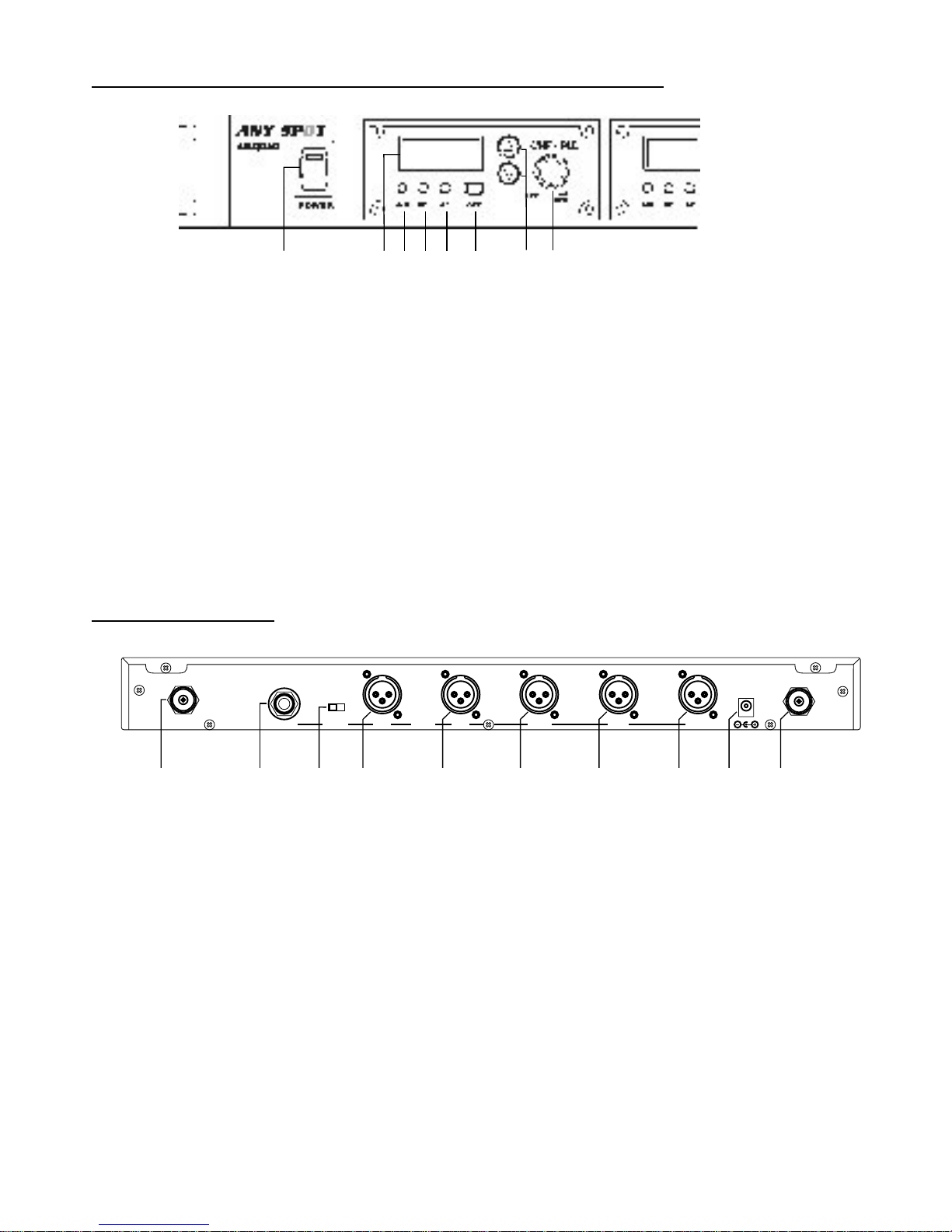
A. Power Supply and Main Power Switch
1. Starting with all power switches off, plug the included
DC Power Supply into the DC Input Jack (17) on the rear
panel. Plug the other end into an AC wall outlet. Switch on
the Main Power (8).
B. Output Jacks
The QUAD offers two different methods of connecting the
Mic Receiver Outputs to the Inputs of devices such as
mixers, amplifiers, or recording gear.
1. You may connect each Receiver Module Output (A
through D, 13-16) to separate input channels on a
mixer. This method is useful when independent signal
processing or routing of the Mic Receivers is required.
Note: The Module Ch. A Output jack (16) corresponds
to the module closest to the Main Power Switch (8) on
the front panel, and so on down the line.
2. Or, you may simply use one (or both) of the Mix
Outputs (10 or 12), which will supply a mix of all the
Receiver Modules based on the Volume settings of
each Module (7). Use the Hi / Lo Switch (11) to
choose the overall Output Level (Mic or Line Level).
This method is useful to conserve mixer input
channels, or when a simple setup is desired that does
not require independent signal processing or routing
of the Mic Receivers.
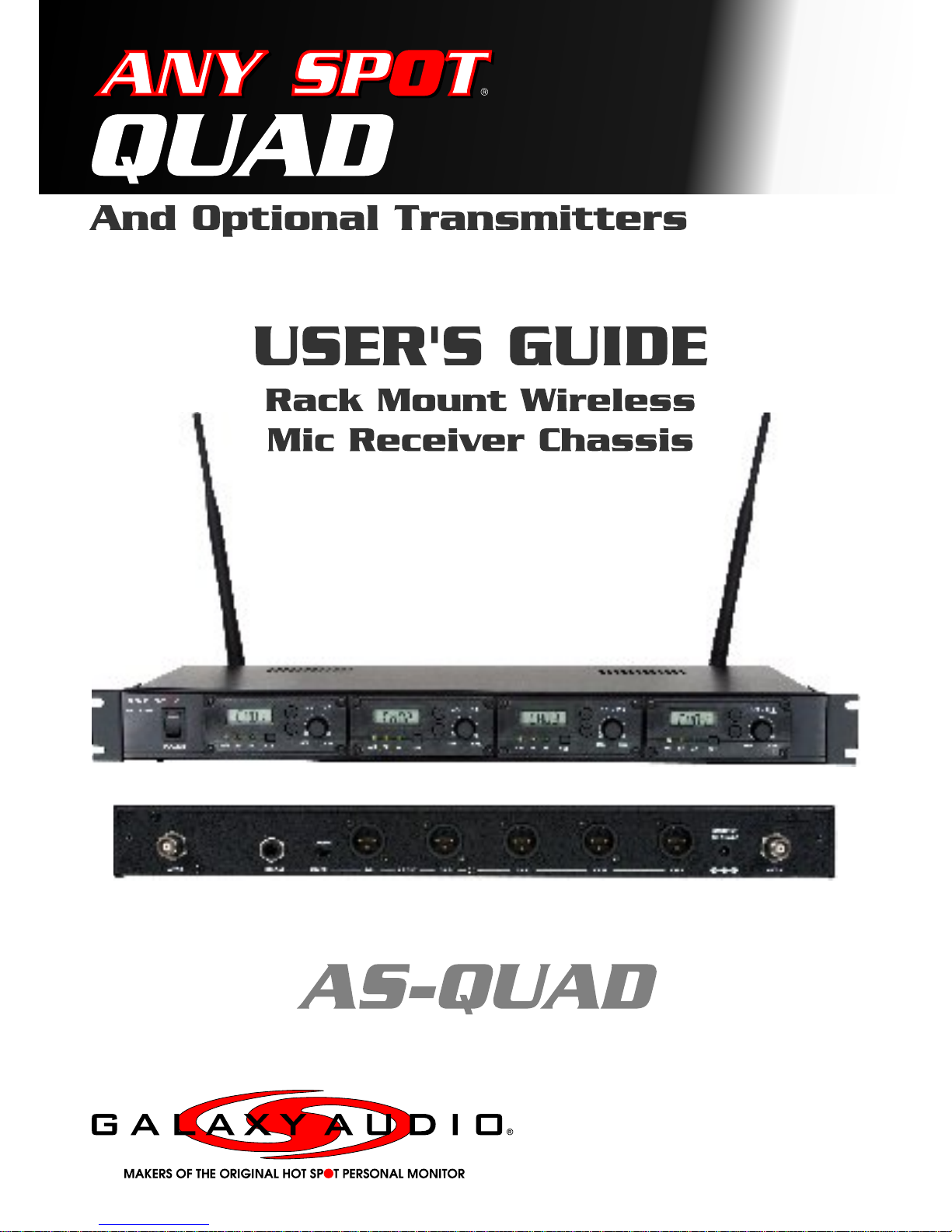
C. Wireless Mic Receiver Modules
This system may be configured with up to four wireless mic
receiver modules with selectable PLL 96 channel
operation. 3
1. Turn the power switch (7) clockwise to turn on the
receiver.
2. The LCD display (1) will show “On” and the channel that
was last in use when the unit was turned off.
3. To select a different channel, press the set button (5).
The channel number will flash in the in LCD display. Press
the up or down button (6) to select a channel to use, and
then press the set button. After a channel has been set,
press either the up or down button to display the frequency
of the selected channel.
4. Adjust the volume controls to the desired level. It is
important to set the gain structure properly to ensure the
best signal to noise ratio. Typically, you will want to set the
Output Volume controls of the Mic Receiver Modules as
high as possible without causing distortion to the Input of
the next device, and so on down the line.
5. When receiving signal, the A/B diversity indicator (2) will
light RED or Green to show the normal condition. The RF
indicator (3) will light to show RF received and the AF
indicator (4) will show audio received.
6. When multiple Transmitters (Mics) are used, each must
be set to a different channel to avoid interference. Set the
Mic Receiver to the same channel number that is set on
the Transmitter that you wish to receive.
Notice: Changes or modifications not expressly approved
by the party responsible for compliance could void the
user's authority to operate the equipment.
4