Galaxy DX 949 User manual


- 1 -
DX 949
TABLE OF
CONTENTS
CHAPTER 1 PAGE
SPECIFICATIONS
1.0 General. . . . . . . . . . . . . . . . . . . . . . . . . . . . . . . . . . . . . . . . . . . . . . . . . 2
1.1 Transmitter. . . . . . . . . . . . . . . . . . . . . . . . . . . . . . . . . . . . . . . . . . . . . . 2
1.2 Receiver. . . . . . . . . . . . . . . . . . . . . . . . . . . . . . . . . . . . . . . . . . . . . . . . 2
CHAPTER 2
OPERATION
2.1 Control & Connections. . . . . . . . . . . . . . . . . . . . . . . . . . . . . . . . . . . . 3
2.1.1 Front Panel . . . . . . . . . . . . . . . . . . . . . . . . . . . . . . . . . . . . . . . . . . . . 3
2.1.2 Rear Panel . . . . . . . . . . . . . . . . . . . . . . . . . . . . . . . . . . . . . . . . . . . . 6
2.1.3 Frequency Chart. . . . . . . . . . . . . . . . . . . . . . . . . . . . . . . . . . . . . . . . . 7
2.2 Microphone. . . . . .. . . . . . . . . . . . . . . . . . . . . . . . . . . . . . . . . . . . . . . 8
2.3.1 Procedure To Receive . . . . . . . . . . . . . . . . . . . . . . . . . . . . . . . . . . . . 8
2.3.2 Procedure To Transmit . . . . . . . . . . . . . . . . . . . . . . . . . . . . . . . . . . . 8
2.4 Alternate Microphones And Installation. . . . . . . . . . . . . . . . . . . . . . . 8
CHAPTER 3
CIRCUIT DESCRIPTION
3.0 Introduction . . . . . . . . . . . . . . . . . . . . . . . . . . . . . . . . . . . . . . . . . . . 11
3.1 PLL Circuit . . . . . . . . . . . . . . . . . . . . . . . . . . . . . . . . . . . . . . . . . . . 11
3.2 Receiver Circuit . . . . . . . . . . . . . . . . . . . . . . . . . . . . . . . . . . . . . . . . 11
3.3 Transmitter Modulation Circuit . . . . . . . . . . . . . . . . . . . . . . .. . . . . . 11
3.4 Transmitter Amplifier Circuit . . . . . . . . . . . .. . . . . . . . . . . . . . . . . . . 11
CHAPTER 4
ALIGNMENT
4.0 Required Test Equipment. . . . . . . . . . . . . . . . . . . . . . . . . . . . . . . . . . 14
4.1 Alignment Procedures . . . . . . . .. . . . . . . . . . . . . . . . . . . . . . . . . . . . . 14
4.1.1 PLL Alignment . . . . . . . . . . . . . . . . . . . . . . . . . . . . . . . . . . . . . . . . . 14
4.1.2 Transmitter Alignment . . . . . . . . . . . . . . . . . . . . . . . . . . . . . . . . . . . 15
4.1.3 Receiver Alignment . . . . . . . . . . . . . . . . . . . . . . . . . . . . . . . . . . . . . 16
CHAPTER 5
MAINTENANCE
5.0 Precautions . . . . . . . . . . . . . . . . . . . . . . . . . . . . . . . . . . . . . . . . . . . . 19
5.1 Periodic Inspection . . . . . . . . . . . . . . . . . . . . . . . . . . . . . . . . . . . . . 19
5.2 Fuse Replacement . . . . . . . . . . . . . . . . . . . . . . . . . . . . . . . . . . . . . . . 19
CHAPTER 6
DIAGRAMS AND PART LIST
6.0 PCB Layout & Part List. . . . . . . . . . . . . . . . . . . . . . . . . . . . . . . . . . . 20
Updates and Corrections. . . . . . . . . . . . . . . . . . . . . . . . . . . . . . . . . . . . . . . . . . . 32

- 2 -
DX 949
CHAPTER 1
SPECIFICATIONS
1.0 GENERAL
Model DX 949
Frequency Range 26.965 - 27.405MHz.
Emission Modes AM/USB/LSB
Frequency Control Phase Lock Loop (PLL) synthesizer.
Frequency Tolerance ±0.005 %.
Frequency Stability ±0.001 %.
Operating Temperature Range -30°C to +50°C.
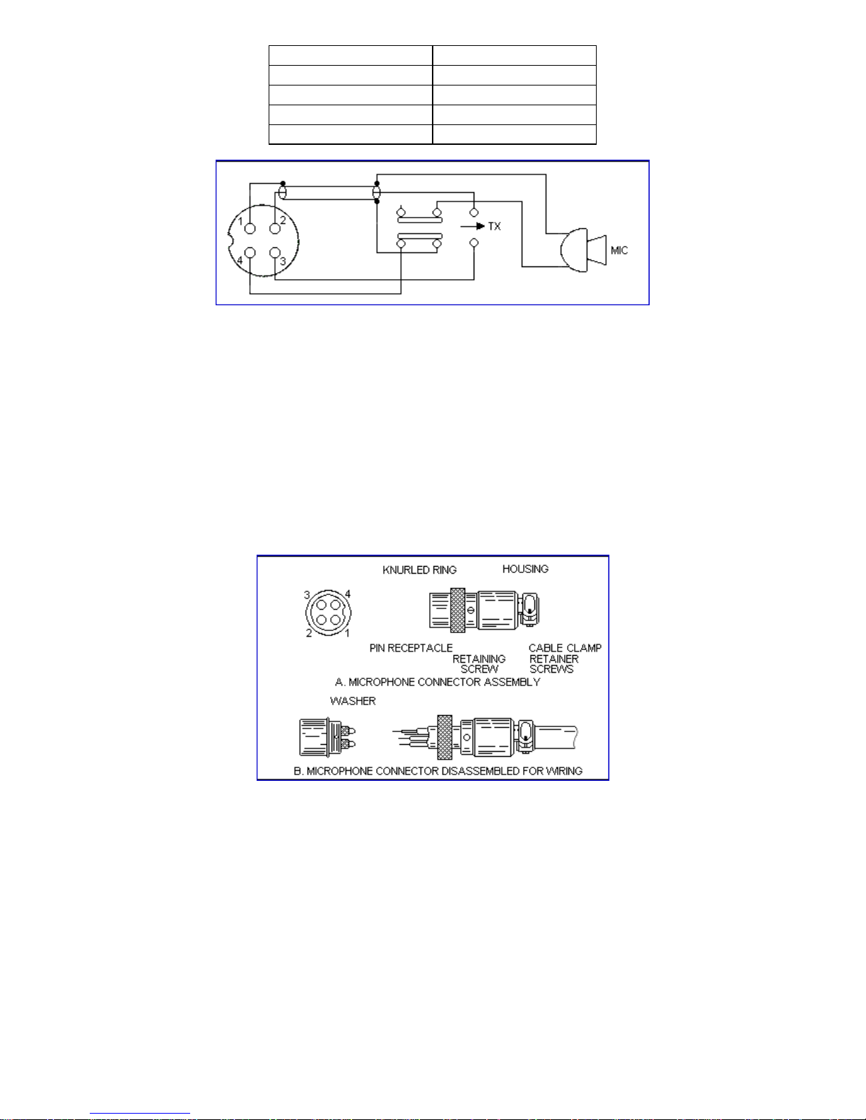
Microphone Plug-in dynamic; with push-to-talk switch and coiled
cord.
Input Voltage 13.8V DC nominal ±15%.
Current Drain : Transmit (AM full mod.) <3.5A.
Current Drain : Receiver (Squelched) <0.5A.
(Max. audio output) <1.0A.
Antenna Connector UHF, SO239.
Dimensions 2-3/8”(H) x 7-7/8”(W) x 9-1/4”(D).
Weight 5 lb.
1.1 TRANSMITTER
RF Power Output AM : 4W SSB : 12W
RF Transmit Modes AM/SSB
Modulation High and low level Class B, Amplitude Modulation :
AM and SSB
Spurious Emissions -55 dB.
Carrier Suppression -55 dB.
Audio Frequency Response 300 to 2500Hz
Antenna Impedance 50 Ohms.
Output Indicators Meter shows relative RF output power, SWR and AM
Modulation. Transmit LED glows red when
transmitter is in operation.
1.2 RECEIVER
Sensitivity For 10dB S/N (AM) <0.5µV
Sensitivity For 10dB S/N (SSB) <0.25µV.
IF Frequency AM : 10.695 MHz 1st IF, 455 KHz 2nd IF.
Image Rejection -65 dB.
Adjacent Channel Selectivity -60 dB.
RF Gain Control 45 dB adjustable for optimum signal reception.
Automatic Gain Control (AGC) Figure Of Merit 100 mV for 10 dB Change in Audio Output
Squelch Adjustable; threshold less than 0.5 µV.
Noise Blanker RF type.
Audio Output Power 2 watts into 8 Ohms.
Audio Frequency Response AM and SSB : 300 to 2500 Hz.
Built-in Speaker 8 Ohms, round.
External Speaker (Not Supplied) 8 Ohms; disables internal speaker when connected.
(SPECIFICATIONS SUBJECT TO CHANGE WITHOUT NOTICE)

- 3 -
DX 949
CHAPTER 2
OPERATION
Figure 2-1 Front Panel
2.0 INTRODUCTION
This section explains the basic operating procedures for the Galaxy DX 949 mobile transceiver.
2.1 CONTROL AND CONNECTIONS
2.1.1 FRONT PANEL
Refer to the above Figure 2-1 for the location of the following controls.
1. SQUELCH CONTROL
This control is used to control or eliminate receiver background noise in the absence of an
incoming signal. For maximum receiver sensitivity, it is desired that the control be adjusted only
to the point where the receiver background noise is eliminated. Turn fully counter-clockwise, then
slowly clockwise until the receiver noise disappears. Any signal to be received must now be
slightly stronger than the average received noise. Further clockwise rotation will increase the
threshold level which a signal must overcome in order to be heard. Only strong signals will be
heard at a maximum clockwise setting.
2. ON/OFF VOLUME CONTROL
Turn clockwise to apply power to the radio and to set the desired listening level.
3. MIC GAIN

- 4 -
Adjusts the microphone gain in the transmit and PA modes. This controls the gain to the extent that
full talk power is available several inches away from the microphone. In the Public Address (PA)
mode, the control functions as the volume control. Pushing this knob turns the Roger Beep on and
off. When the Roger Beep is on, the radio transmits an audio tone at the end of your transmission.
This indicates the end of your transmission so that people who are having trouble hearing you will
know that you are done speaking. As a courtesy to others, use the Roger Beep only when necessary.
4. RF GAIN CONTROL
This control is used to reduce the gain of the receive amplifier under strong signal conditions.
5. DIMMER CONTROL
This knob controls the level of brightness for the meter lamp and the LED channel display. Also,
pushing this knob turns the meter lamp and the display LED’s on and off.
6. RF POWER CONTROL
This control allows the user to adjust RF power output.
7. CHANNEL SELECTOR
This control is used to select a desired transmit and receive channel.
8. FRONT PANEL METER
The Front Panel Meter allows the user to monitor signal strength, RF output power, SWR level and
AM modulation level.
9. TALKBACK CONTROL
Pushing this knob turns the Talkback circuit on and off. Adjust this knob for desired volume of
Talkback. This is used to monitor your own voice. For example, you could use this feature to
compare different microphones.
10. CLARIFIER
Allows tuning of the receive frequency above or below the channel frequency by up to 1.0 KHz.
Although this control is intended primarily to tune in SSB signals, it may be used to optimize AM
signals .
11. SWR/MOD/ PWR SWITCH
This switch controls the function of the meter during the transmit mode. In the SWR position, the
meter indicates the Standing Wave Ratio (SWR) of your antenna. There are no adjustments because
the SWR circuit in this radio calibrates itself automatically. When the switch is in the MOD
position, the green scale on the meter indicates your percentage of modulation. This operates in AM
only, not in SSB. When this switch is in PWR position, the meter indicates your power output.
12. NB/ANL/OFF SWITCH
In the ANL position, the Automatic Noise Limiter is activated. When the switch is placed in the
NB/ANL position, the RF Noise Blanker is also activated. The Noise Blanker is very effective in
eliminating repetitive impulse noise such as ignition interference.
13. PA/GNF/CB SWITCH

- 5 -
In the PA position, your voice will come out of the speaker that you need to plug in to the PA. SP.
jack on the rear panel. The radio does not operate when you are in the PA mode. The CB mode is
normal operation of the radio. In the GNF mode, you are in CB operation but the Galaxy Noise
Filter is engaged. This is a special noise filter that de-emphasizes audio high frequency response in
order to increase the signal-to-noise ratio of weak signals. While you will notice a dramatic
reduction in the “rushing” sound when this filter is activated, it does not have much effect on the
signal-to-noise ratio of strong signals. It is mostly used for SSB reception.
14. MODE SWITCH
This control allows you to select one of the following operating modes : USB/AM/LSB .
15. TONE SWITCH HI/MED/LO
This switch changes tone quality in receive only. In LO position, bass is increased and in HI
position, treble is increased.
16. CHANNEL DISPLAY
The channel display indicates the current selected channel.
17. SWR ALERT LED
This LED lights red when your SWR is higher than about 3:1. This is not an exact indicator of 3:1
SWR, but it is an indication that you should check your SWR reading.
18. R.B. LED
This lights green when the Roger Beep is on.
19. RX/TX LED
This LED lights green during receive and red during transmit.
2.1.2 REAR PANEL

- 6 -
Figure 2-2 represent the location of the following connections :
Figure 2-2 Rear Panel
1. ANTENNA
This jack accepts 50 ohms coaxial cable with a PL- 259 type plug.
2. POWER
This connector accepts 13.8V DC power cable with built-in fuse. The power cord provided with the
radio has a black and red wire. The black goes to negative and the red goes to positive.
3. FREQUENCY COUNTER CONNECTOR
This connector is for the optional Galaxy FC 347 six digit frequency counter. All connections are
made through this connector. No soldering is required.
4. PA. SP.
This jack is for PA operation. Before operating, you must first connect a PA speaker ( 8 ohms, 4W )
to this jack.
5. EXT. SP.
This jack accepts 4 to 8 ohms, 5 watts external speaker. When the external speaker is connected to
this jack, the built-in speaker will be disabled.
2.1.3 FREQUENCY CHART

- 7 -
CHANNEL CHANNEL FREQUENCY CHANNEL CHANNEL FREQUENCY
1 26.965 MHz 21 27.215 MHz
2 26.975 MHz 22 27.225 MHz
3 26.985 MHz 23 27.255 MHz
4 27.005 MHz 24 27.235 MHz
5 27.015 MHz 25 27.245 MHz
6 27.025 MHz 26 27.265 MHz
7 27.035 MHz 27 27.275 MHz
8 27.055 MHz 28 27.285 MHz
9 27.065 MHz 29 27.295 MHz
10 27.075 MHz 30 27.305 MHz
11 27.085 MHz 31 27.315 MHz
12 27.105 MHz 32 27.325 MHz
13 27.115 MHz 33 27.335 MHz
14 27.125 MHz 34 27.345 MHz
15 27.135 MHz 35 27.355 MHz
16 27.155 MHz 36 27.365 MHz
17 27.165 MHz 37 27.375 MHz
18 27.175 MHz 38 27.385 MHz
19 27.185 MHz 39 27.395 MHz
20 27.205 MHz 40 27.405 MHz
2.2 MICROPHONE

- 8 -
The receiver and transmitter are controlled by the push-to-talk switch on the microphone. Press the
switch and the transmitter is activated, release switch to receive. When transmitting, hold the
microphone two inches from the mouth and speak clearly in a normal voice. The radio comes
complete with low impedance (500 ohm) dynamic microphone. For installation instructions of the
microphone, see section “ALTERNATE MICROPHONES AND INSTALLATION”.
2.3 OPERATION
2.3.1 PROCEDURE TO RECEIVE
1. Be sure that power source, microphone and antenna are connected to the proper connectors
before going to the next step.
2. Turn unit on by running VOL knob clockwise on transceiver.
3. Set the VOL to a comfortable listening level.
4. Set the MODE switch to the desired mode.
5. Listen to the background noise from the speaker. Turn the SQ knob slowly clockwise until the
noise just disappears. Leave the control at this setting. This SQ is now properly adjusted. The
receiver will remain quiet until a signal is actually received. Do not advance the control too far or
some of weaker signals will not be heard.
6. Set the CHANNEL selector switch to the desired channel.
7. Set the RF gain control fully clockwise for maximum receive gain.
2.3.2 PROCEDURE TO TRANSMIT
1. Select the desired channel of transmission
2. Set the MIC GAIN control fully clockwise.
3. If the channel is clear, depress the push-to-talk switch on the microphone and speak in a normal
voice.
2.4 ALTERNATE MICROPHONES AND INSTALLATION
For best results, the user should select a low impedance dynamic type microphone or a
transistorized microphone. Transistorized type microphones have a low output impedance
characteristic. The microphones must be provided with a four-lead cable. The audio conductor and
its shielded lead comprise two of the leads. The third lead is for transmit control and the fourth is
for receive control. The microphone should provide the functions shown in schematic below
(Figure 2-3).
4 WIRE MIC CABLE

- 9 -
Pin Number Mic Cable Lead
1 Audio Shield
2 Audio Lead
3 Transmit Control
4 Receive Control
Figure 2-3 Your Transceiver Microphone Schematic
If the microphone to be used is provided with pre-cut leads, they must be revised as follows :
(i) Cut leads so that they extend 7/16” beyond the plastic insulating jacket of the microphone cable.
(ii) All leads should be cut to the same length. Strip the ends of each wire 1/8” and tin the exposed
wire.
Before beginning the actual wiring read carefully, the circuit and wiring information provided with
the microphone you select. Use the minimum head required in soldering the connections. Keep the
exposed wire lengths to a minimum to avoid shorting when the microphone plug is reassembled.
Figure 2-4 Microphone Plug Wiring

- 10 -
To wire microphone cable to the plug provided, proceed as follows :
(i) Remove the retaining screw.
(ii) Unscrew the housing from the pin receptacle body.
(iii) Loosen the two cable clamp retainer screws.
(iv) Feed the microphone cable through the housing, knurled ring and washer as shown Figure 2-4.
(v) The wires must now be soldered to the pins as indicated in the above wiring tables. If a vise or
clamping tool is available it should be used to hold the pin receptacle body during the soldering
operation, so that both hands are free to perform the soldering. If a vise or clamping tool is not
available, the pin receptacle body can be held in a stationary position by inserting it into the
microphone jack of the front panel. The numbers of the pins of the microphone plug are shown in
Figure 2-5, as viewed from the back of the plug. Before soldering the wire to the pins, pre-tin the
wire receptacle of each pin of the plug.
Figure 2-5 Microphone plug pin numbers viewed from rear of pin receptacle.
Be sure that the housing and the knurled ring of Figure 2-3 are pushed back onto the microphone
cable before starting to solder. If the washer is not captive to the pin receptacle body, make sure that
it is placed on the threaded portion of the pin receptacle body before soldering.
(vi) When all soldering connections to the pins of the microphone plug are complete, push the
knurled ring and the housing forward and screw the housing onto the threaded portion of the pin
receptacle body. Note the location of the screw clearance hole in the plug housing with respect to
the threaded hole in the pin receptacle body. When the housing is completely threaded into the pin
receptacle body, a final fraction of a turn either clockwise or counter-clockwise may be required to
align the screw hole with the threaded hole in the pin receptacle body. When these are aligned, the
retaining screw is then screwed into the place to secure the housing to the pin receptacle body.
(vii) The two cable clamp retainer screws should now be tightened to secure the housing to the
microphone cord. If the cutting directions have been carefully followed, the cable clamp should
secure to the insulating jacket of the microphone cable.
(viii) Upon completion of the microphone plug wiring, connect and secure the microphone plug in
the transceiver.
CHAPTER 3

- 11 -
DX 949
CIRCUIT
DESCRIPTION
3.0 INTRODUCTION
This section explains the technical theory of operation for the Galaxy DX 949 mobile transceiver.
3.1 PLL CIRCUIT
The Phase Lock Loop (PLL) circuit is responsible for developing the receiver’s first local oscillator
signal and the transmitter’s exciter signal. The PLL circuit consists primarily of IC2, IC3, Q25,
Q27, Q28 and Q61. The PLL circuit is programmed by the user’s rotary channel switch GPS-501.
The switch allows GPS-501 to communicate the correct binary data information to the
programmable divider inside of IC3. IC3 then controls the VCO (Voltage Controlled Oscillator),
consisting of VCO to oscillate on the correct frequency. This signal is fed either into the receiver’s
first mixer (for receive operation) or the transmitter’s mixer (for transmit operation).
3.2 RECEIVER CIRCUIT
The incoming receive signal come into the radio via the antenna and into the front end pre-amp
consisting of Q17. The RF signal is fed into the mixer circuit of the Q18 and then into the AM IF
section of the receiver (depending on the mode of operation). The signal is then detected by either
the AM detector or product detector and then fed to the audio amplifier section of the receiver and
finally out to the speaker.
3.3 TRANSMITTER MODULATION CIRCUIT
(i) The transmitter modulation circuit modulates the low level RF signal from the PLL exciter
circuit with the user’s audio voice signal from the microphone. The audio from the microphone is
then amplified and fed into the balanced modulator circuit.
(ii) If the transceiver is in the AM mode, the AF amplifier controls directly the RF amplifier gain of
the last RF amplifier which produces a true amplitude modulation RF signal.
(iii) If the transceiver is in the SSB mode, the audio signal is mixed with 10.6975MHz oscillator in
IC6.
3.4 TRANSMITTER AMPLIFIER CIRCUIT
The transmitter takes the basic exciter signal from the TX mixer and amplifies it through a series of
amplifiers consisting of Q50, Q51, Q49 and Q47 where it is sent out to the antenna connector.
DX 949 BLOCK DIAGRAM

- 12 -
DX 949 CIRCUIT DIAGRAM

- 13 -
CHAPTER 4

- 14 -
DX 949 ALIGNMENT
4.0 REQUIRED TEST EQUIPMENT
cDC Power Supply (13.8VDC, 10A)
dRF Wattmeter (25~60 MHz, 25W)
eMultimeter
fAutomatic Modulation Meter
gAudio Signal Generator
hFrequency Counter (100 MHz)
iRF Signal Generator (100 MHz)
jAutomatic Distortion Meter
kOscilloscope (50 MHz)
lSinad Meter
4.1 ALIGNMENT PROCEDURES
This transceiver has been aligned at the factory and does not require any adjustments at installation.
The required test equipment listed are used for the test setup or alignment shown in Figure 4-1
Transmitter Test Setup and Figure 4-2 Receiver Test Setup. These test setup are used in part or total
during the following adjustments and refer to Figure 4-3 for adjustment location.
4.1.1 PLL ALIGNMENT
ITEM U.U.T. SETTING ADJUST
POINT
MEASUREMENT
VCO Voltage Disconnect the “short PCB” from TP7,
TP8 and TP9. Set radio to CH 1 AM RX
mode. Clarifier setting in 12 o’clock.
Connect Oscilloscope to TP3.
Set radio to CH 1 AM RX mode.
Connect frequency counter IC 3 Pin 8
L14
L15
VC1
2.6 VDC ±0.1
Maximum Output
10.24000 MHz + 20 Hz
AM
Frequency
Set radio to CH 1 AM RX mode.
Connect frequency counter to TP3.
L20 16.27000 MHz + 20 Hz
USB Freq.
Set radio to CH 1 USB mode.
Connect frequency counter to TP3.
L21 16.27250 MHz + 20 Hz
LSB Freq.
Set radio to CH 1 LSB mode.
Connect frequency counter to TP3.
L22 16.26750 MHz + 20 Hz
TX Frequency
Offset
Set radio to CH 1 LSB TX mode.
Connect frequency counter to TP3
VR7 16.26750 MHz + 20 Hz
AM OSC Set radio to CH 1 AM TX mode.
Connect frequency counter to TP5
L23 10.69500 MHz + 20 Hz
USB OSC
Set radio to CH 1 USB TX mode. Set VR6
fully clockwise. Connect frequency
counter to TP5.
L24 10.69250 MHz + 20 Hz
LSB OSC
Set radio to CH 1 LSB TX mode. Connect
frequency counter to TP5. Connect scope
to TP5 and adjust VR6 for minimum
signal.
L25 10.69750 MHz + 20 Hz

- 15 -
4.1.2 TRANSMITTER ALIGNMENT
ITEM U.U.T. SETTING ADJUST
POINT
MEASUREMENT
BIAS Current
Set radio to CH 19 USB TX mode. MOD off.
Connect current meter to TP7(+) and TP9(-)
Connect current meter to TP7(+) and TP8(-)
VR12
VR10
50 mA
100 mA
SSB TX Power
Set radio to CH 19, USB TX mode.
Connect “short PCB” to TP7 and TP9.
Connect RF power meter to antenna jack.
AF signal 30 mV, 1 KHz to microphone.
L40, L42,
L43, L44
L40, L42
MAX ≥12W
Spurious emission
Min.
Balance Power
Between CH 1 and
CH 40.
SSB ALC Audio signal 30 mV, 1 KHz to microphone.
Set radio to CH 19, USB TX mode.
VR13 11.5 W
SSB Carrier
Balance
Set radio to CH 19, USB TX mode. Mic Gain
off. Connect scope to Antenna Connector.
VR6 Spurious Emission
To Minimum.
SSB APC Set radio to CH 19, USB mode.
MOD off. Connect Voltmeter to TP7.
VR17 DC12.5V
AM TX Power Set radio to CH 19 AM TX mode.
No MOD.
VR14 3.8W
RF Power
Meter
Set radio to CH 19 AM TX mode. Mod off. VR9 Adjust RF Power
meter to “4” on
PWR scale.
AM
Modulation
Set radio to CH 19 TX mode.
Audio signal 30 mV, 1 KHz to microphone.
Set Mic Gain Fully Clockwise.
VR16 90%
4.1.3 RECEIVER ALIGNMENT

- 16 -
ITEM U.U.T. SETTING ADJUST
POINT
MEASUREMENT
AM Sensitivity Set radio to CH 19 AM RX MODE.
Clarifier setting at 12 o’clock.
RF Gain fully clockwise,
SQ fully counter clockwise.
VOL control at 2 o’clock.
Connect RF SG to antenna jack
Output Frequency 27.185 MHz, MOD 30%.
Set radio to CH 40 AM mode.
RF SG setting 27.405 MHz.
Set radio to CH 1 AM mode.
RF SG setting 26.965 MHz.
L2, L3, L5,
L6, L7, L8,
L9, L10
L6, L7
Audio output > 2V
S/N 10 dB
For Balance
between CH 1 and
CH 40
USB Sensitivity
Set radio to CH 19 USB mode.
VOL control fully clockwise.
RF SG setting to 27.186 MHz @ 0.5 uV
MOD to off
L11, L12 Audio output > 2V
S/N 10 dB
LSB Sensitivity
Set radio to CH 19 LSB mode.
VOL control fully clockwise.
RF SG setting to 27.184 MHz @ 0.5 uV
MOD to off
L11, L12 Audio output > 2V
S/N 10 dB
NB Adjust Set radio to CH 19 AM mode
RF SG setting 27.205 MHz @ 100 uV
MOD 30%, NB/ANL switch on.
Connect Voltmeter to TP1
L1 DC voltage to max.
(>2.0V)
AM Squelch Set radio to CH 19 AM mode
SQ control at fully clockwise.
RF SG setting 10 mV, MOD 30%
VR4
Slowly
Adjust very slowly
until squelch just
closes
SSB Squelch
Set radio to CH 19 USB mode.
SQ control fully clockwise.
RF SG setting 10 mV
VR3
Slowly
Adjust very slowly
until squelch just
closes
AM S/RF Meter
AM S-Meter
Set radio to CH 19 AM mode.
Meter switch at S/RF position.
RF SG setting to 27.185 MHz @ 100 uV
MOD 30%,
VR1 Meter needle to S9
on the S scale
SSB S-Meter Set radio to CH 19 USB mode.
S/RF switch at S/RF position.
RF SG setting 27.186 Mhz, MOD off 100 uV
VR2 Meter needle to S9
on the S scale
Figure 4-1 Transmitter test setup

- 17 -
Figure 4-2 Receiver test setup

- 18 -
Figure 4-3 Main PCB Adjustment Locations
CHAPTER 5

- 19 -
DX 949 MAINTENANCE
5.0 PRECAUTIONS
The inherent quality of the solid-state components used in this transceiver will provide many years
of continuous use. Taking the following precautions will prevent damage to the transceiver.
(i) Never key the transmitter unless an antenna or suitable dummy load is connected to the antenna
receptacle.
(ii) Ensure that the input voltage does not exceed 16 VDC or fall below 11 VDC.
(iii) During alignment, do not transmit for more than 10 seconds at a time. Transmitting over long
periods can cause heat built-up and cause transmitter damage.
5.1 PERIODIC INSPECTION
This unit is aligned at the factory to deliver maximum performance. However, continued
performance cannot be expected without periodic inspection and maintenance. Important points to
be checked regularly are as follows;
Check Item Action
Whip antenna
(option)
If cracked or broken, replace it.
Coaxial cable If sheath is cracked, seal with
vinyl tape. If immersed with
water, install new coaxial cable.
Coaxial & power
plug connections
If loosened, reconnect. If
corroded, clean contacts.
Battery connection If corroded, clean power
terminals.
Ground terminal If corroded, clean terminal.
5.2 FUSE REPLACEMENT
To protect the equipment from serious damage, one fuse are provided on the power supply lines.
The fuses protect against over voltage / reverse polarity of the vehicle’s mains or internal fault of
the equipment. If the fuse has blown, first find out the cause of the trouble before replacing it. A
fuse rated for more than 4A should not be used, since it may permanently damage the equipment.
Damage due to over fusing is not covered by the warranty.
CHAPTER 6
Other manuals for DX 949
1
Table of contents
Other Galaxy Radio manuals