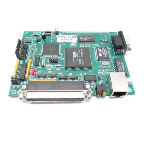
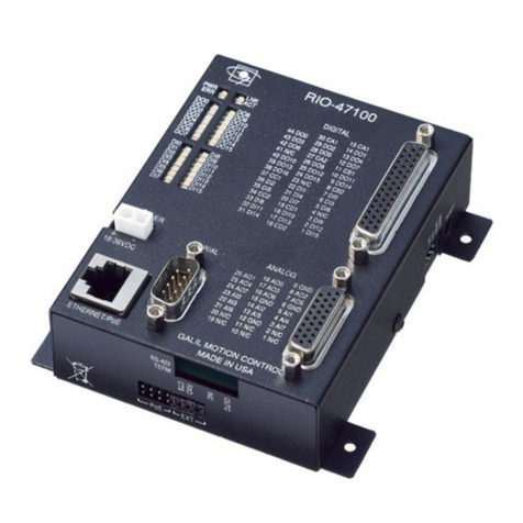
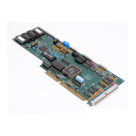
Galil Motion Control RIO-47120 User manual


Contents
CONTENTS ...................................................................................................................................................... I
CHAPTER 1 OVERVIEW ..............................................................................................................................1
INTRODUCTION ...............................................................................................................................................1
PART NUMBERING OVERVIEW ........................................................................................................................2
RIO-47XX0VS.RIO-47XX2...........................................................................................................................3
RIO Functional Elements..........................................................................................................................3
CHAPTER 2 GETTING STARTED...............................................................................................................4
RIO-471XX.....................................................................................................................................................4
RIO-472XX.....................................................................................................................................................5
INSTALLING THE RIO BOARD .........................................................................................................................5
Step 1. Configure Jumpers ........................................................................................................................5
Step 2. Connecting Power to the RIO........................................................................................................6
Step 3. Install the Communications Software............................................................................................7
Step 4. Establish Communications between RIO and the Host PC...........................................................7
Communicating to the RIO using Galil Software......................................................................................7
Using Non-Galil Communication Software..............................................................................................7
CHAPTER 3 COMMUNICATION ..............................................................................................................10
INTRODUCTION .............................................................................................................................................10
RS232 PORT .................................................................................................................................................10
RS-232 Configuration .............................................................................................................................10
ETHERNET CONFIGURATION .........................................................................................................................10
Communication Protocols.......................................................................................................................10
Jumper Configuration for 10BaseT.........................................................................................................11
Addressing...............................................................................................................................................11
Email from the RIO.................................................................................................................................12
Communicating with Multiple Devices...................................................................................................12
Handling Communication Errors ............................................................................................................13
Multicasting.............................................................................................................................................13
Unsolicited Message Handling................................................................................................................13
Other Protocols Supported ......................................................................................................................14
MODBUS WITH THE RIO ...............................................................................................................................14
Raw Modbus Send/Receive.....................................................................................................................15
Modbus Read/Write to Array Table........................................................................................................15
Sending Modbus Packets.........................................................................................................................15
Modbus Exceptions.................................................................................................................................15
Function Code 1 ($01) - Read Coils........................................................................................................17
Function Code 2 ($02) - Read Discrete Inputs........................................................................................19
RIO-47xxx Contents ●i

Function Code 3 ($03) - Read Holding Registers ...................................................................................21
Function Code 4 ($04) - Read Input Registers........................................................................................24
Function Code 5 ($05) - Write Single Coil .............................................................................................27
Function Code 6 ($06) - Preset Single Register ......................................................................................29
Function Code 7 ($07) – Read Exception Status.....................................................................................31
Function Code 15 ($0F) – Write Multiple Coils .....................................................................................33
Function Code 16 ($10) – Write Multiple Registers ...............................................................................35
Analog IO Ranges...................................................................................................................................38
DATA RECORD..............................................................................................................................................39
QR and DR Commands...........................................................................................................................39
RIO Data Record.....................................................................................................................................39
Explanation of Status Information...........................................................................................................40
CHAPTER 4 I/O .............................................................................................................................................41
INTRODUCTION .............................................................................................................................................41
SPECIFICATIONS............................................................................................................................................41
Digital Outputs........................................................................................................................................41
Digital Inputs...........................................................................................................................................44
Analog Outputs .......................................................................................................................................45
Analog Inputs..........................................................................................................................................45
Analog Process Control Loop .................................................................................................................47
CHAPTER 5 PROGRAMMING...................................................................................................................49
OVERVIEW....................................................................................................................................................49
EDITING PROGRAMS .....................................................................................................................................49
PROGRAM FORMAT.......................................................................................................................................49
Using Labels in Programs .......................................................................................................................50
Special Labels .........................................................................................................................................50
Commenting Programs............................................................................................................................50
Program Lines Greater than 40 Characters..............................................................................................51
Lock Program Access using Password....................................................................................................51
EXECUTING PROGRAMS -MULTITASKING.....................................................................................................52
DEBUGGING PROGRAMS ...............................................................................................................................52
Trace Commands.....................................................................................................................................53
Error Code Command .............................................................................................................................53
RAM Memory Interrogation Commands ................................................................................................53
Operands .................................................................................................................................................53
Debugging Example:...............................................................................................................................53
PROGRAM FLOW COMMANDS .......................................................................................................................54
Interrupts .................................................................................................................................................54
Examples:................................................................................................................................................55
Conditional Jumps...................................................................................................................................56
Using If, Else, and Endif Commands......................................................................................................58
Stack Manipulation..................................................................................................................................59
Auto-Start Routine ..................................................................................................................................59
Automatic Subroutines for Monitoring Conditions.................................................................................59
MATHEMATICAL AND FUNCTIONAL EXPRESSIONS........................................................................................61
Mathematical Operators..........................................................................................................................61
Bit-Wise Operators..................................................................................................................................63
Functions.................................................................................................................................................64
VARIABLES ...................................................................................................................................................64
Programmable Variables.........................................................................................................................64
OPERANDS ....................................................................................................................................................65
Examples of Internal Variables:..............................................................................................................65
Special Operands (Keywords).................................................................................................................66
ARRAYS........................................................................................................................................................66
ii Contents RIO-47xxx

Defining Arrays.......................................................................................................................................66
Assignment of Array Entries...................................................................................................................66
Using a Variable to Address Array Elements..........................................................................................67
Uploading and Downloading Arrays to On Board Memory....................................................................67
Automatic Data Capture into Arrays.......................................................................................................67
Deallocating Array Space........................................................................................................................68
INPUT OF DATA (NUMERIC AND STRING)......................................................................................................69
Input of Data............................................................................................................................................69
OUTPUT OF DATA (NUMERIC AND STRING)..................................................................................................69
Sending Messages ...................................................................................................................................69
Displaying Variables and Arrays.............................................................................................................71
Formatting Variables and Array Elements..............................................................................................71
PROGRAMMABLE I/O....................................................................................................................................72
Digital Outputs........................................................................................................................................72
Digital Inputs...........................................................................................................................................73
Analog Inputs..........................................................................................................................................73
Analog Outputs .......................................................................................................................................74
REAL TIME CLOCK........................................................................................................................................74
APPENDIX......................................................................................................................................................75
ELECTRICAL SPECIFICATIONS .......................................................................................................................75
Input/Output............................................................................................................................................75
Power Requirements................................................................................................................................75
PERFORMANCE SPECIFICATIONS ...................................................................................................................76
RIO-47xx0...............................................................................................................................................76
RIO-47xx2...............................................................................................................................................76
CERTIFICATIONS ...........................................................................................................................................76
ETL .........................................................................................................................................................76
CE............................................................................................................................................................76
ROHS......................................................................................................................................................76
STANDARD OPTIONS.....................................................................................................................................77
-DIN ........................................................................................................................................................77
-NO DIN..................................................................................................................................................77
-422 .........................................................................................................................................................77
-RTC........................................................................................................................................................77
-08-15 SOURCE (2LSRC) option...........................................................................................................78
-0-7 or -8-15 SINK/SOURCE.................................................................................................................78
-QUAD and -SSI.....................................................................................................................................78
-PWM......................................................................................................................................................79
-HS ..........................................................................................................................................................80
-16Bit.......................................................................................................................................................80
AI_10v12Bit............................................................................................................................................81
AI_10v16Bit............................................................................................................................................81
-(4-20mA)................................................................................................................................................81
AO Option (SCB-48608).........................................................................................................................81
CONNECTORS FOR RIO-47XXX.....................................................................................................................83
44 pin D-Sub Connector – RIO-471xx....................................................................................................83
26 pin D-Sub Connector – RIO-471xx....................................................................................................83
Screw Terminals – RIO-472xx................................................................................................................84
J2 RS-232 Port: DB-9 Pin Male.............................................................................................................84
J1 Ethernet Port: 10/100 Base-T (RJ-45) ................................................................................................85
J5 Power: 2 pin Molex.............................................................................................................................85
JUMPER DESCRIPTION FOR RIO ....................................................................................................................86
RIO DIMENSIONS..........................................................................................................................................87
RIO-471xx...............................................................................................................................................87
RIO-472xx...............................................................................................................................................88
RIO-47xxx Contents ●iii

ACCESSORIES AND OPTIONS .........................................................................................................................89
LIST OF OTHER PUBLICATIONS .....................................................................................................................90
CONTACTING US...........................................................................................................................................90
TRAINING SEMINARS ....................................................................................................................................91
WARRANTY...............................................................................................................................................92
A1 – SCB-48206 ..............................................................................................................................................93
DESCRIPTION ................................................................................................................................................93
SPECIFICATIONS............................................................................................................................................94
WIRING.........................................................................................................................................................94
OPERATION...................................................................................................................................................94
Method 1 .................................................................................................................................................95
Method 2 .................................................................................................................................................96
A2 – SCB-48306/48316 ...................................................................................................................................97
DESCRIPTION ................................................................................................................................................97
SPECIFICATIONS............................................................................................................................................98
WIRING.........................................................................................................................................................98
OPERATION...................................................................................................................................................99
INDEX ...........................................................................................................................................................100
iv Contents RIO-47xxx

Chapter 1 Overview
Introduction
Derived from the same fundamentals used in building the Galil motion controllers, the RIO-47xxx is a
programmable remote I/O controller that conveniently interfaces with other Galil boards through its Ethernet
port. The RIO is programmed exactly the same way as a DMC (Digital Motion Controller) with the
exception of a few revised commands and the removal of all motion-related commands. Communication
with the RIO even works the same way as with other Galil controllers, and it utilizes the same software
programs. Interrogation commands have been included to allow a user to instantly view the entire I/O status,
I/O hardware, or Ethernet handle availability (see the TZ, ID and TH commands).
The purpose of an RIO board is to offer remote I/O in a system and the ability to synchronize complex
events. To do this, the RIO consists of two boards – a high speed processor with integrated Ethernet and an
I/O board consisting of digital inputs, digital outputs, analog inputs, and analog outputs. If different I/O
requirements are required –a custom I/O board can be made to mate up directly with the RIO processor.
RIO-47xxx Chapter 1 Overview ●1

Part Numbering Overview
Highlights Options
RIO-47100 Metal case
0-5V Analog IO
8 high power optoisolated digital outputs
8 low power optoisolated digital outputs
16 optoisolated digital inputs
-DIN
-08-15 SOURCE
-HS
-422
-4-20mA
-PWM
RIO-47102 Same as RIO-47100 but with expanded memory -DIN
-08-15 SOURCE
-HS
-422
-4-20mA
-RTC
-PWM
RIO-47120 Same as RIO-47100 but with +-10V analog IO -DIN
-08-15 SOURCE
-16 Bit
-422
-HS
-4-20mA
-PWM
RIO-47122 Same as RIO-47120 but with expanded memory -DIN
-08-15 SOURCE
-16 Bit
-422
-HS
-4-20mA
-RTC
-PWM
-QUAD
-SSI
RIO-47200 Same as RIO-47100 except
-Screw terminals instead of D-Subs
-Din rail mount with metal cover
-All 16 outputs are high power
-No analog outputs (use AO option to add analog)
-422
-0-7 SINK or -0-7 SOURCE
-8-15 SINK or -8-15SOURCE
-HS
-10V12-Bit
-10V16-Bit
-NO DIN
-4-20mA
-PWM
(8AO_5v_12bit),
(8AO_10v12bit),(8AO_10v16bit)
For details on all the options please see Standard Options in the Appendix.
2 Chapter 1 Overview RIO-47xxx

RIO-47xx0 vs. RIO-47xx2
Controller # of array
elements
# of
program
lines
# of
variables # of labels # of control
loops
# of
Ethernet
handles
RIO-47xx0 400 200 126 62 2 3
RIO-47xx2 1000 400 256 126 6 5
RIO Functional Elements
Microcomputer Section
The main processing unit of the RIO is a specialized 32-bit Freescale Microcomputer with 32KB SRAM and
256KB of Embedded Flash memory. The SRAM provides memory for variables, array elements and
application programs. The flash memory provides non-volatile storage of variables, programs, and arrays; it
also contains the RIO firmware. The RIO can process individual Galil Commands in approximately 40
microseconds.
The RIO product line has a maximum of 10,000 write cycles for burning (BN, BP, BV combined).
Communication
The communication interface with the RIO consists of one RS-232 port (default is 115 kBaud/s) and one
10/100Base-T Ethernet port (jumper configurable).
There are four status LEDs on the RIO that indicate operating and error conditions on the controller. Figure
1-1 shows a diagram of the LED bank followed by the description of the four lights.
PWR
ERR LNK
ACT
Figure 1-1 - Diagram of LED bank on the RIO
Green Power LED (PWR) - The green status LED indicates that the power has been applied
properly to the RIO.
Red Status/Error LED (ERR) - The red error LED will flash on briefly at power up. After the
initial power up condition, the LED will illuminate for the following reasons:
1. The reset line on the controller is held low or is being affected by noise.
2. There is a failure on the controller and the processor is resetting itself.
3. There is a failure with the output IC that drives the error signal.
Green Link LED (LNK) – The green LED indicates there is a valid Ethernet connection. This
LED will show that the physical Ethernet layer (the cable) is connected.
Activity (ACT) – The amber LED indicates traffic across the Ethernet connection. This LED will
show both transmit and receive activity across the connection.
RIO-47xxx Chapter 1 Overview ●3

Chapter 2 Getting Started
RIO-471xx
Figure 1: Outline of RIO-471xx (Dimensions listed in the Appendix)
4 Chapter 2 Getting Started RIO-47xxx

RIO-472xx
Figure 2: Outline of RIO-472xx (Dimensions listed in the Appendix)
Installing the RIO Board
Installation of a complete, operational RIO system consists of 4 steps:
Step 1. Configure jumpers
Step 2. Connect power to the RIO
Step 3. Install the communications software
Step 4. Establish communications between the RIO and the host PC
Step 1. Configure Jumpers
Power Input Jumpers (AUX vs PoE)
The RIO can be powered using either a 18-36V DC power input or a PoE (Power over Ethernet) switch to
deliver power over the Ethernet cable. The default configuration is the 18-36VDC power input. If PoE is
used, the four jumpers on JP6 for the RIO-471xx and JP1 for the RIO-472xx must be moved from AUX to
PoE.
Master Reset and Upgrade Jumper
Jumpers labeled as MRST and UPGD are located at JP5 for the RIO-471xx and JP2 for the RIO-472xx, next
to the reset button. The MRST jumper is for a master reset. When MRST is jumpered, the RIO will perform
a master reset upon a power cycle to the board or when the board reset button is pushed. Whenever the I/O
board has a master reset, all programs, arrays, and variables stored in non-volatile memory will be erased –
this will set the RIO board back to factory defaults.
RIO-47xxx Chapter 2 Getting Started ●5

The UPGD jumper enables the user to unconditionally update the board firmware. This jumper is not
necessary for firmware updates when the RIO board is operating normally, but may be necessary in cases of
a corrupted non-volatile memory. non-volatile memory corruption should never occur under normal
operating circumstances; however, corruption is possible if there is a power fault during a firmware update.
If non-volatile memory corruption occurs, your board may not operate properly. In this case, install the
UPGD jumper and use the update firmware function in the Galil software to re-load the system firmware.
Setting the Baud Rate on the RIO
The default baud rate for the RIO is 115K (jumper OFF).
The jumper labeled “19.2,” also located at JP5 for the RIO-471xx and JP2 for the RIO-472xx, allows the user
to select the serial communication baud rate. The baud rate can be set using the following table:
19.2 BAUD RATE
OFF 115k
ON 19.2k
Step 2. Connecting Power to the RIO
Since the RIO can be powered using either a 18-36V DC power input or a PoE (Power over Ethernet) switch,
there are two possible connection options shown here:
1) EXT: 18-36VDC power input is the default configuration. The four jumpers on JP6 for the RIO-471xx
and JP1 for the RIO-472xx . Apply a DC power supply in the range of 18-36V to the 2-pin molex
connector. The power supply should be capable of delivering up to 4 Watts. The RIO uses Molex Pitch
Mini-Fit, Jr.™ Receptacle Housing connectors for connecting DC Power. For more information on the
connectors, go to http://www.molex.com/.
Note: The part number listed below is the connector that is found on the controller. For more information see
the Molex website. http://www.molex.com/
Molex Part Number Pin Part Number (x2) Type
39-31-0020 44476-3112 2 Position
Warning: Damage can occur if a supply larger than 36VDC is connected to the board.
2) PoE: Power over Ethernet. This configuration needs the four jumpers on JP6 for the RIO-471xx and JP1
for the RIO-472xx to be placed on the side labeled PoE. Once this is done, the controller will derive its
power directly from the Ethernet cable. A PoE style switch can be used such as the FS108P from Netgear.
Applying power will turn on the green LED power indicator.
6 Chapter 2 Getting Started RIO-47xxx

Step 3. Install the Communications Software
After applying power to the computer, install the Galil software that enables communication between the I/O
board and your PC. It is strongly recommended to use the Galil software “GalilTools” when communicating
to the RIO unit. Please see the GalilTools Manual for a complete description of how to install and connect to
Serial or Ethernet controllers.
http://www.galilmc.com/products/software/galiltools.html
Step 4. Establish Communications between RIO and the Host PC
Communicating to the RIO using Galil Software
RS-232:
To use serial communication, connect a 9pin straight-through RS-232 cable (CABLE-9-PIND) between the
serial port of the RIO and the computer or terminal communications port. The RIO serial port is configured
as DATASET.
Ethernet:
Connect the RIO Ethernet port to your computer via a crossover Ethernet cable, or to a network hub with a
straight through Ethernet cable.
Using Non-Galil Communication Software
RS-232:
The RIO serial port is configured as DATASET. The computer or terminal must be configured as a for full
duplex, no parity, 8 data bits, one start bit and one stop bit. A standard Windows HyperTerminal session can
connect to the controller using a straight-through serial cable.
Check to insure that the baud rate jumpers have been set to the desired baud rate as described above. Also,
the hardware handshake lines (RTS/CTS) need to be connected. See Chapter 3 for more information on
‘Handshake Modes.’
Ethernet:
Connect the RIO Ethernet port to your computer via an Ethernet crossover cable, or to a network hub by a
straight through Ethernet cable. An IP address needs to be assigned via a DHCP server, through Galil
software, or via a serial cable using the IA command. See Chapter 3 for more information on how to
establish an IP address. Once an IP address is established, a standard Windows Telnet session can connect to
the controller.
* Note that the RIO-471x2 supports auto-crossover detection (auto MDIX)
Sending Test Commands to the Terminal after a successful Connection
After connecting to the computer or terminal, press <carriage return> or the <enter> key on the keyboard. In
response to carriage return {CR}, the controller responds with a colon, :
Now type
RIO-47xxx Chapter 2 Getting Started ●7

TZ {CR}
This command directs the RIO to return the current I/O status. The controller should respond with something
similar to the following:
:TZ
Block 0 (7-0) Inputs - value 255 (1111_1111)
Block 1 (15-8) Inputs - value 255 (1111_1111)
Block 0 (7-0) Outputs - value 0 (0000_0000)
Block 1 (15-8) Outputs - value 0 (0000_0000)
Analog Inputs(7-0)
0.0000,0.0000,0.0000,0.0000,0.0037,0.0012,0.0000,0.0000
Analog Outputs(7-0)
0.0000,0.0000,0.0000,0.0000,0.0000,0.0000,0.0000,0.0000
8 Chapter 2 Getting Started RIO-47xxx

RIO Web Server
The RIO has a built-in web server that can be accessed by typing the IP address of the controller into a
standard web browser. The controller comes from the factory without any IP address assigned so a user must
go through the steps outlined above to establish an IP address before the web-server is accessible. Figure 3
shows an output of the RIO Web Server:
Figure 3: RIO Web Server Output
RIO-47xxx Chapter 2 Getting Started ●9

Chapter 3 Communication
Introduction
The RIO has one RS-232 port and one Ethernet port. The RS-232 port is the data set, and it is a standard
serial link with a communication baud rate up to 115kbaud. The Ethernet port is jumper configurable for 10
or 100Base-T (default).
RS232 Port
The RIO board has a single RS232 connection for sending and receiving commands from a PC or other
terminal. The pin-outs for the RS232 connection can be found in the Appendix - J5 Power: 2 pin Molex.
RS-232 Configuration
Configure the PC for 8 data bits, no parity, one stop bit, and hardware handshaking. The baud rate for the
RS232 communication defaults to 115k baud but can be set to 19.2k baud by placing a jumper on J5. The
serial port has a 4 bytes FIFO.
Handshaking Modes
The RS232 port is configured for hardware handshaking. In this mode, the RTS and CTS lines are used. The
CTS line will go high whenever the RIO is not ready to receive additional characters. The RTS line will
inhibit the RIO board from sending additional characters. Note: The RTS line goes high for inhibit. This
handshake procedure is required and ensures proper communication especially at higher baud rates.
Ethernet Configuration
Communication Protocols
The Ethernet is a local area network through which information is transferred in units known as packets.
Communication protocols are necessary to dictate how these packets are sent and received. The RIO
supports two industry standard protocols, TCP/IP and UDP/IP. The board will automatically respond in the
format in which it is contacted.
10 Chapter 3 Communication RIO-47xxx

TCP/IP is a "connection" protocol. The master must be connected to the slave in order to begin
communicating. Each packet sent is acknowledged when received. If no acknowledgement is received, the
information is assumed lost and is resent.
Unlike TCP/IP, UDP/IP does not require a "connection". This protocol is similar to communicating via
RS232. If a cable is unplugged, the device sending the packet does not know that the information was not
received on the other side. Because the protocol does not provide for lost information, the sender must re-
send the packet.
Galil recommends using TCP/IP for standard communication to insure that if a packet is lost or destroyed
while in transit, it will be resent. However UDP is recommended in certain situations such as launching Data
Record information to a host for graphing or data collection.
Each packet must be limited to 470 data bytes or less. This is not an issue when using Galil software as the
Galil Ethernet driver will take care of the low level communication requirements.
The IK command blocks the controller from receiving packets on Ethernet ports lower than 1000 except for
ports 0, 23, 25, 68, 80 and 502. To receive packets on all ports, set IK to 0.
NOTE: In order not to lose information in transit, Galil recommends that the user wait for an
acknowledgement of receipt of a packet before sending the next packet.
Jumper Configuration for 10BaseT
If 10BaseT communication is required, a jumper must be placed on the pins labeled OPT. The default is no
jumper which is 100BaseT Ethernet communication.
Addressing
There are three levels of addresses that define Ethernet devices. The first is the MAC or hardware address.
This is a unique and permanent 6 byte number. No other device will have the same MAC address. The RIO
MAC address is set by the factory and the last two bytes of the address are the serial number of the board.
To find the Ethernet MAC address for a RIO unit, use the TH command. A sample is shown here with a unit
that has a serial number of 3:
Sample MAC Ethernet Address: 00-50-4C-28-00-03
The second level of addressing is the IP address. This is a 32-bit (or 4 byte) number that usually looks like
this: 192.168.15.1. The IP address is constrained by each local network and must be assigned locally.
Assigning an IP address to the RIO board can be done in a number of ways.
The first method for setting the IP address is using a DHCP server. The DH command controls whether the
RIO board will get an IP address from the DHCP server. If the unit is set to DH1 (default) and there is a
DHCP server on the network, the controller will be dynamically assigned an IP address from the server.
Setting the board to DH0 will prevent the controller from being assigned an IP address from the server.
The second method to assign an IP address is to use the BOOT-P utility via the Ethernet connection. The
BOOT-P functionality is only enabled when DH is set to 0. Either a BOOT-P server on the internal network
or the Galil software may be used. When opening the Galil Software, it will respond with a list of all RIO
boards and controllers on the network that do not currently have IP addresses. The user must select the board
and the software will assign the specified IP address to it. This address will be burned into the controller
(BN) internally to save the IP address to the non-volatile memory. Note: if multiple boards are on the
network – use the serial numbers to differentiate them.
CAUTION: Be sure that there is only one BOOT-P or DHCP server running. If your network has
DHCP or BOOT-P running, it may automatically assign an IP address to the RIO board upon linking
it to the network. In order to ensure that the IP address is correct, please contact your system
administrator before connecting the I/O board to the Ethernet network.
RIO-47xxx Chapter 3 Communication ●11

The third method for setting an IP address is to send the IA command through the RS-232 port. (Note: The
IA command is only valid if DH0 is set). The IP address may be entered as a 4 byte number delimited by
commas (industry standard uses periods) or a signed 32 bit number (e.g. IA 124,51,29,31 or IA 2083724575).
Type in BN to save the IP address to the RIO non-volatile memory.
NOTE: Galil strongly recommends that the IP address selected is not one that can be accessed across the
Gateway. The Gateway is an application that controls communication between an internal network and the
outside world.
The third level of Ethernet addressing is the UDP or TCP port number. The Galil board does not require a
specific port number. The port number is established by the client or master each time it connects to the RIO
board. Typical port numbers for applications are:
Port 23: Telnet
Port 502: Modbus
Port 80: HTTP
Email from the RIO
If the RIO is on a network with a SMTP Mail Server, the RIO is capable of sending an email message using
the MG command. There are three configuration commands necessary to send an email from the RIO unit –
MA, MS and MD. MA sets the smtp email server IP address. MS sets the email source or “from” address
and MD sets the destination or “to” address. There is a maximum character limit for the MS and MD
commands of 30 characters. An example of this is shown here:
MA 10,0,0,1; ‘example SMTP Email Server IP address
MD someone@example.com; ‘sample destination email address
MS me@example.com; ‘sample source address
MG "Testing Email"{M}; ‘Message to send via Email
Please contact your system administrator for information regarding email settings.
Note: it is strongly recommended that the email messaging frequency is limited so as not to overload the
email server.
Communicating with Multiple Devices
The RIO is capable of supporting multiple masters or slaves. A typical scenario would be connecting a PC (a
master) and a motion controller (a 2nd master) that can both send commands to the RIO board over Ethernet
on different handles.
Note: The term “master” is equivalent to the Internet “client” and the term “slave” is equivalent to the
Internet “server”.
An Ethernet handle is a communication resource within a device. The RIO-47xx0 can have a maximum of 3
Ethernet handles open at any time. This number is increased to 5 Ethernet handles on the RIO-47xx2. If all
handles are in use and another device tries to connect, it will be sent a "reset packet" showing that the RIO
cannot establish any new connections.
NOTE: A reset will cause the Ethernet connection to be lost. There are a number of ways to reset the board.
Hardware resets (push reset button or power down RIO board) and software resets (through Ethernet or
RS232 by entering the RS command).
When the RIO acts as the master, the IH command is used to assign handles and connect to its slaves. The IP
address may be entered as a 4 byte number separated with commas (industry standard uses periods) or as a
signed 32 bit number. A port number may also be specified, but if it is not, it will default to 1000. The
protocol (TCP/IP or UDP/IP) to use must also be designated at this time. Otherwise, the board will not
12 Chapter 3 Communication RIO-47xxx

connect to the slave. (Ex: IHB=151,25,255,9<179>2. This will open handle #2 and connect to the IP
address 151.25.255.9, port 179, using TCP/IP)
Once the IH command is used to connect to slaves, the user can communicate to these slaves by sending
commands to the master. The SA command is used for this purpose, and it has the following syntax.
SAh= "command string"
Here "command string" will be sent to handle h. For example, SAA=”XQ” command will send an XQ
command to the slave/server on handle A. A more flexible form of the command is
SAh= field1,field2,field3,field4 ... field8
where each field can be a string in quotes or a variable.
When the Master/client sends an SA command to a Slave/server, it is possible for the master to determine the
status of the command. The response _IHh4 will return the number 1 to 4. 1 indicates waiting for the
acknowledgement from the slave. 2 indicates a colon (command accepted) has been received. 3 indicates a
question mark (command rejected) has been received. 4 indicates the command timed out.
If a command generates multiple responses (such as the TE command), the values will be stored in _SAh0
thru _SAhn where n is the last field. If a field is unused, its _SA value will be -2^31.
See the Command Reference for more information on the SA command.
Which devices receive what information from the RIO depends on various things. If a device queries the
RIO, it will receive the response unless it explicitly tells the RIO to send it to another device. If the
command that generates a response is part of a downloaded program, the response will route to whichever
port is specified by the CF command (either a specific Ethernet handle or the RS232 port). If the user wants
to send the message to a port other than what is specified by the CF command, add an {Eh} or {P1} to the
end of the command (Ex. MG{EB}"Hello" will send the message "Hello" to handle #2 and MG{P1}”Hello”
will send it to the serial port).
Handling Communication Errors
A reserved automatic subroutine which is identified by the label #TCPERR can be used to catch
communication errors. If an RIO has an application program running and the TCP communication is lost, the
#TCPERR routine will automatically execute. The #TCPERR routine should be ended with the RE
command.
Multicasting
A multicast may only be used in UDP/IP and is similar to a broadcast (where everyone on the network gets
the information) but specific to a group. In other words, all devices within a specified group will receive the
information that is sent in a multicast. There can be many multicast groups on a network and are
differentiated by their multicast IP address. To communicate with all the devices in a specific multicast
group, the information can be sent to the multicast IP address rather than to each individual device IP
address. All Galil devices belong to a default multicast address of 239.255.19.56. This multicast IP address
can be changed by using the IA>u command.
Unsolicited Message Handling
Unsolicited messages are any messages that are sent from the controller that are not directly requested by the
host PC. An example of this is a MG or TP command inside of a program running on the controller. Error
messages are also “unsolicited” because they can come out at any time. There are two software commands
that will configure how the controller handles these unsolicited messages: CW and CF.
The RIO has 3 Ethernet handles as well as 1 serial port where unsolicited messages may be sent. The CF
command is used to configure the controller to send these messages to specific ports. In addition, the Galil
RIO-47xxx Chapter 3 Communication ●13

software has various options for sending messages using the CF command. For more information, see the CF
command description in the Command Reference.
The CW command has two data fields that affect unsolicited messages. The first field configures the most
significant bit (MSB) of the message. A value of 1 will set the MSB of unsolicited messages, while a value
of 2 suppresses the MSB. Programs like HyperTerminal or Telnet need to use a setting of CW2 for the
unsolicited messages to be readable in standard ASCII format. However, the Galil software needs a value of
CW1 to be set so that it can differentiate between solicited and unsolicited messages. If you have difficulty
receiving characters from the controller, or receive garbage characters instead of messages, check the status
of the CW command.
The second field of the CW command controls whether the product should pause while waiting for the
hardware handshake to enable the transmission of characters over RS-232 (CW,0), or continue processing
commands and lose characters until the hardware handshake allows characters to be sent (CW,1).\
Other Protocols Supported
Galil supports DHCP, ARP, BOOT-P, and Ping, which are utilities for establishing Ethernet connections.
ARP is an application that determines the Ethernet (hardware) address of a device at a specific IP address.
BOOT-P is an application that determines which devices on the network do not have an IP address and
assigns the IP address you have chosen to it. Ping is used to check the communication between the device at
a specific IP address and the host computer.
The RIO can communicate with a host computer through any application that can send TCP/IP or UDP/IP
packets. A good example of this is Telnet, a utility that comes standard with the Windows operating system.
When using DHCP and a DNS (Domain Name Server), the DNS will assign the name “RIO47100-n” to the
controller where n is the serial number of the unit.
Modbus with the RIO
The RIO-47xxx supports Modbus/TCP, and requires an Ethernet connection between its master or slave
devices.
As a Modbus class 1 device, the RIO supports the following Modbus function codes:
Function Code Modbus Description Galil Description
1 Read Coil Status Read Digital Outputs
2 Read Input Status Read Digital Inputs
3 Read Holding Registers Read Analog Inputs
4 Read Input Registers Read Analog Outputs
5 Force Single Coil Write Digital Output
6 Preset Single Register Write Digital Outputs
7 Read Exception Status Read Digital Outputs
15 Force Multiple Coils Write Digital Outputs
16 Preset Multiple Registers Write Analog Outputs
Of the Modbus function codes the RIO supports, all are supported by the RIO when it operates as a master
(also known as a client) or when it operates as a slave (server).
Note 1: By default the RIO uses function code 3 for analog inputs and function code 4 for analog outputs.
For a majority of Modbus devices this functionality is inverted. Use the MV command to switch the
functionality. Please see the command reference for details.
Note 2: The remainder of this document uses the '$' symbol to signify that numbers are in hexadecimal
notation.
14 Chapter 3 Communication RIO-47xxx
This manual suits for next models
6
Table of contents
Other Galil Motion Control Controllers manuals

Galil Motion Control
Galil Motion Control DMC-1000 User manual

Galil Motion Control
Galil Motion Control RIO-47 seriesRIO-47100 User manual

Galil Motion Control
Galil Motion Control DMC-14 5 Series User manual

Galil Motion Control
Galil Motion Control DMC-40x0 Series Installation manual

Galil Motion Control
Galil Motion Control DMC-1600 Series User manual

Galil Motion Control
Galil Motion Control DMC-42 0 Series User manual

Galil Motion Control
Galil Motion Control DMC-18 2 Series User manual

Galil Motion Control
Galil Motion Control DMC-500 Series User manual

Galil Motion Control
Galil Motion Control DMC-4040 User manual