Gallagher T12 User manual

Page 1
3E4720 Gallagher T12 Reader | Edion 12 | May 2023
Copyright © Gallagher Group Limited
Gallagher
T12 Reader
InstallaƟon Note
T12 MIFARE®Reader, Black: C300420
T12 MIFARE®Reader, White: C300421
T12 MulƟTech Reader, Black: C300440
T12 MulƟTech Reader, White: C300441
High Sec T12 Reader, Black: C305420
High Sec T12 Reader, White: C305421
T12 MulƟTech Reader, Black Not PoƩed: C300440-01

Page 2
3E4720 Gallagher T12 Reader | Edion 12 | May 2023
Copyright © Gallagher Group Limited
Disclaimer
This document gives certain informaon about products and/or services provided by Gallagher Group Limited
or its related companies (referred to as "Gallagher Group").
The informaon is indicave only and is subject to change without noce meaning it may be out of date at any
given me. Although every commercially reasonable effort has been taken to ensure the quality and accuracy
of the informaon, Gallagher Group makes no representaon as to its accuracy or completeness and it should
not be relied on as such. To the extent permied by law, all express or implied, or other representaons or
warranes in relaon to the informaon are expressly excluded.
Neither Gallagher Group nor any of its directors, employees or other representaves shall be responsible
for any loss that you may incur, either directly or indirectly, arising from any use or decisions based on the
informaon provided.
Except where stated otherwise, the informaon is subject to copyright owned by Gallagher Group and you may
not sell it without permission. Gallagher Group is the owner of all trademarks reproduced in this informaon.
All trademarks which are not the property of Gallagher Group, are acknowledged.
Copyright © Gallagher Group Ltd 2023. All rights reserved.

Page 3
3E4720 Gallagher T12 Reader | Edion 12 | May 2023
Copyright © Gallagher Group Limited
Contents
1 Introducon ..................................................................................................................................... 3
2 Before you begin.............................................................................................................................. 4
3 Distance between readers ............................................................................................................... 6
4 Installaon ....................................................................................................................................... 7
5 LED indicaons................................................................................................................................. 9
6 Accessories ...................................................................................................................................... 9
7 Technical specificaons.................................................................................................................. 10
8 Approvals and Compliance Standards............................................................................................10
9 Mounng dimensions .................................................................................................................... 12
1 IntroducƟon
The Gallagher T12 Reader is a smart card and Bluetooth® low energy technology reader. It can be
installed as either an entry reader or exit reader. It can be mounted on a BS 4662 Brish Standard
square flush box.
The reader sends informaon to the Gallagher Controller and acts upon informaon sent from the
Gallagher Controller. The reader itself does not make any access decisions. The reader is available in
four variants. The supported technologies and compability for each variant is shown below.
Reader
Variant
Product
Codes
Card Technologies
Supported
NFC Access
for Android
Supported
From
Bluetooth®
Access
Supported
From
HBUS
Comms
Supported
From
Cardax IV
Comms
Supported
From
T12
MIFARE
Reader
C300420
C300421
ISO 14443A MIFARE®
DESFire® EV1/EV2*/EV3**,
MIFARE Plus®, and MIFARE
Classic® cards
vEL7.80
HBUS only
None vEL7.00 vEL1.02
T12
Mul
Tech
Reader
C300440
C300441
C300440-01
ISO 14443A MIFARE
DESFire EV1/EV2*/EV3**,
MIFARE Plus, MIFARE
Classic, and 125 KHz cards
vEL7.80
HBUS only
vEL7.60
HBUS only
vEL7.00 vEL1.02***
High
Sec T12
Reader
C305420
C305421
ISO 14443A PIV, PIV-I, CAC,
TWIC, MIFARE DESFire
EV1/EV2*/EV3**, MIFARE
Plus, and MIFARE Classic
cards
vEL7.80
HBUS only
None vEL7.10 None
* MIFARE DESFire EV2 is supported from vEL7.70.
** MIFARE DESFire EV3 is supported from vEL8.30.1458 (or later).
*** Gallagher strongly recommends against using dual technology 125/MIFARE cards with MulTech
Readers for sites running pre-Command Centre v7.00 soware. From Command Centre v7.00, a site
may specify which technology a MulTech Reader should read offa dual technology card.

Page 4
3E4720 Gallagher T12 Reader | Edion 12 | May 2023
Copyright © Gallagher Group Limited
2 Before you begin
2.1 Shipment contents
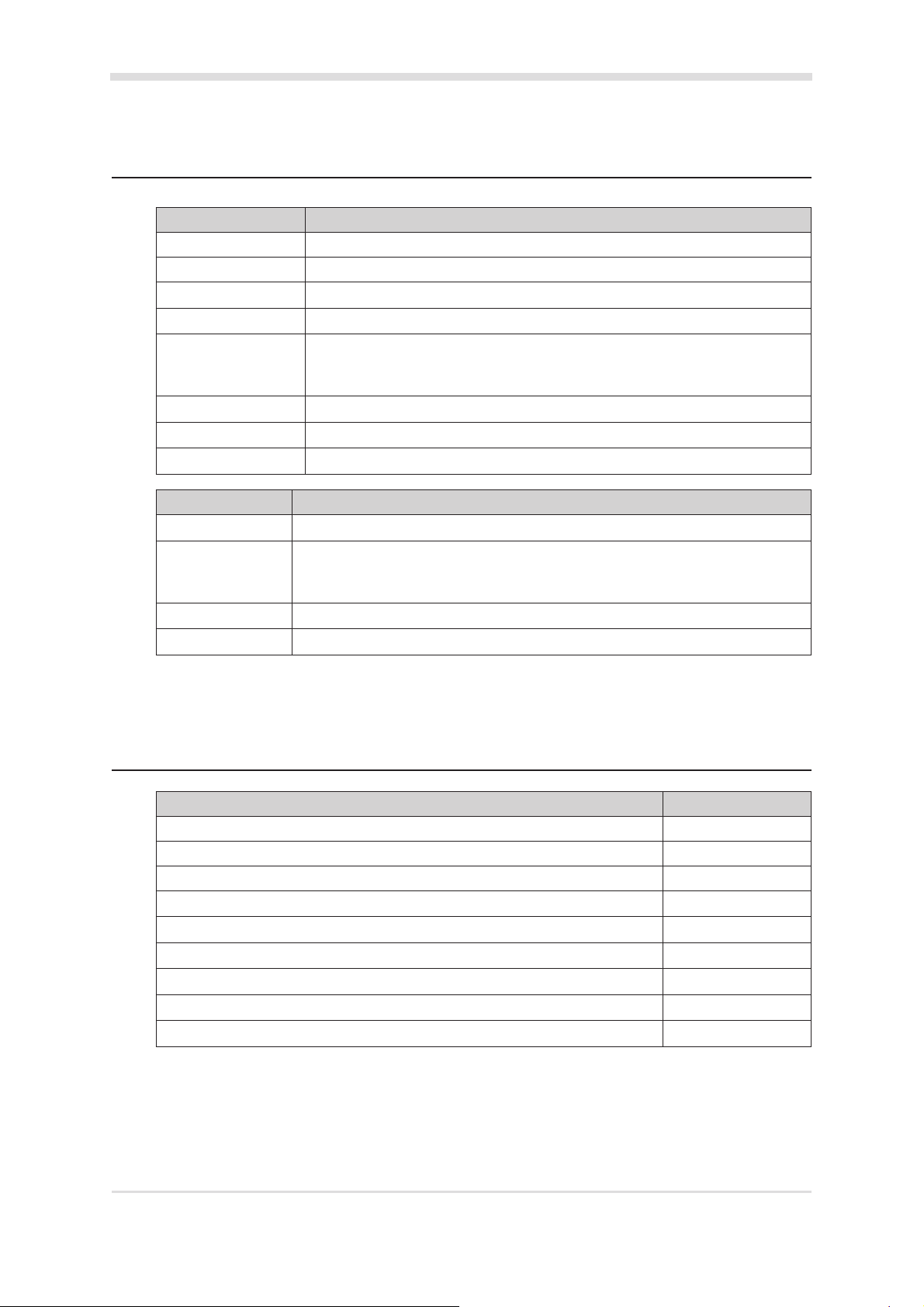
Check the shipment contains the following items:
• 1 x Gallagher T12 Reader facia assembly
• 1 x Gallagher T12 Reader bezel
• 1 x M3 Torx Post Security screw
• 2 x M3.5 Phillips drive fixing screws
• 4 x 25 mm No.6 self tapping, pan head, Phillips drive fixing screws
• 4 x 40 mm No.6 self tapping, pan head, Phillips drive fixing screws
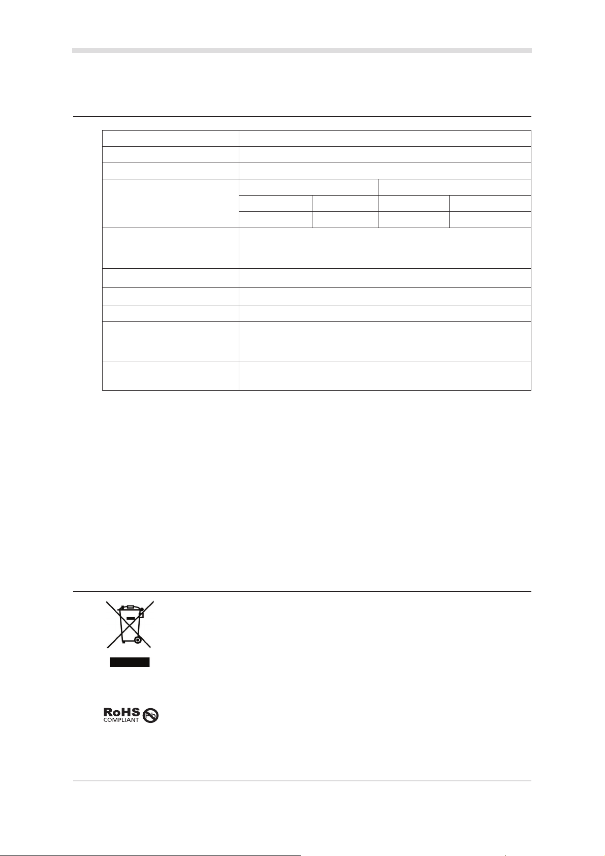
2.2 Power supply
The Gallagher T12 Reader is designed to operate at a supply voltage of 13.6Vdc measured at the
reader terminals. The operang current draw is dependant on the supply voltage at the reader.
For a MIFARE reader, at 13.6 Vdc the current draw is 50 mA (idle). During credenal read, beeper
and LED acvity, the current will momentarily reach 77 mA (maximum). For a MulTech reader,
at 13.6 Vdc the current draw is 80 mA (idle) and will momentarily reach 142 mA (maximum). The
power source should be linear or a good quality switched-mode power supply. The performance
of the reader may be affected by a low quality, noisy power supply.
2.3 Cabling
The Gallagher T12 Reader requires a minimum cable size of 4 core 24 AWG (0.2 mm2) stranded
security cable. This cable allows the transmission of data (2 wires) and power (2 wires). When
using a single cable to carry both power supply and data, both the power supply voltage drop
and data requirements must be considered. For good engineering design it is recommended that
the voltage at the reader should be approximately 12 Vdc.
HBUS cabling topology
The HBUS communicaons protocol is based on the RS485 standard and allows the reader to
communicate over a distance of up to 500 m (1640 ).
The cabling between HBUS devices should be done in a "daisy chain" topology, (i.e. A "T" or
"Star" topology should not be used between devices). Should "Star" or "Home-Run" wiring be
required, the HBUS 4H/8H Modules and the HBUS Door Module allow mulple HBUS devices to
be individually wired to the one physical locaon.
The end devices on the HBUS cable should be terminated using 120 ohms resistance. To
terminate the Gallagher Controller 6000, connect the supplied on-board terminaon jumpers
to the Controller. To terminate a reader, connect the orange (terminaon) wire to the green
(HBUS A) wire. Terminaon is already included at the HBUS Module, (i.e. each HBUS port is
permanently terminated at the module).

Page 5
3E4720 Gallagher T12 Reader | Edion 12 | May 2023
Copyright © Gallagher Group Limited
Connect the on-board
terminaon jumper
Controller 6000
RS485 1
HBUS
Device
"T" or "Star" circuits are
not permied between
HBUS devices
HBUS
Device
Terminate
HBUS
Device
HBUS
Device
HBUS
Device
HBUS
Device
HBUS
Device
HBUS
Device
Terminate
Remove the on-board
terminaon jumper
RS485 1
"T" or "Star" circuits are
not permied between
HBUS devices
HBUS
Device
Terminate
HBUS
Device Controller 6000
Controller 6000
H1 H4
H8
H5
HBUS
Device
Terminate
HBUS
Device
Terminate
HBUS Module
HBUS
Device
HBUS
Device
Terminate
HBUS
Device
Terminate
HBUS
Device

Page 6
3E4720 Gallagher T12 Reader | Edion 12 | May 2023
Copyright © Gallagher Group Limited
Cable distance
Cable type Cable format* HBUS
single reader
connected
using data
only in a single
cable
Cardax IV
single reader
connected
using data
only in a single
cable***
HBUS/Cardax IV
single reader
connected using
power and
data in a single
cable****
CAT 5e or
beer**
4 twisted pair each 2 x
0.2 mm2 (24 AWG)
500 m (1640 ) 200 m (650 ) 100 m (330 )
BELDEN
9842**
(shielded)
2 twisted pair each 2 x
0.2 mm2 (24 AWG)
500 m (1640 ) 200 m (650 ) 100 m (330 )
SEC472 4 x 0.2 mm2 Not
twisted pairs (24 AWG)
400 m (1310 ) 200 m (650 ) 100 m (330 )
SEC4142 4 x 0.4 mm2 Not
twisted pairs (21 AWG)
400 m (1310 ) 200 m (650 ) 150 m (500 )
C303900/
C303901
Gallagher
HBUS Cable
2 Twisted pair each 2
x 0.4 mm2 (21 AWG,
Data) and 2 x 0.75 mm2
Not Twisted Pair (~18
AWG, Power)
500 m (1640 ) 200 m (650 ) 450 m (1490 )
* The matching of wire sizes to equivalent wire gauges are only approximate.
** Recommended cable types for opmal HBUS RS485 performance.
*** Not applicable for Bluetooth® enabled reader installaons.
**** Tested with 13.6V at start of cable.
Notes:
• Shielded cable may reduce the obtainable cable length. Shielded cable should be
grounded at the Controller end only.
• If other cable types are used, operang distances and performance may be reduced
depending on the cable quality.
• HBUS allows up to 20 readers to be connected to a single cable. Each reader requires at
least 9 Vdc to funcon correctly. The cable length and the number of readers connected
will have an impact on the voltage at each reader.
3 Distance between readers
The distance separang any two proximity readers must not be less than 200 mm (8 in) in all direcons.
When mounng a proximity reader on an internal wall, check that any reader fixed to the other side of
the wall is not less than 200 mm (8 in) away.
200 mm
200 mm

Page 7
3E4720 Gallagher T12 Reader | Edion 12 | May 2023
Copyright © Gallagher Group Limited
4 InstallaƟon
ATTENTION: This equipment contains components that can be damaged by
electrostac discharge. Ensure both you and the equipment are earthed before
beginning any servicing.
The Gallagher T12 Reader is designed to be mounted on a standard Brish electrical flush box, or any
solid flat surface. However installaon on metal surfaces, parcularly those with a large surface area
will reduce read range. The extent to which the range is reduced will depend upon the type of metal
surface.
Note: Consideraon should be given to the installaon environment when using Bluetooth® enabled
readers, as the read range may be reduced.
The recommended mounng height for the reader is 1.1 m (3.6 ) from the floor level to the centre of
the reader device. However this may vary in some countries and you should check local regulaons for
variaons to this height.
1. Ensure the building cable has been run out through the flush box.
If you are not mounng to a flush box, use the reader bezel as a guide to drill all five holes. Drill
the 13 mm (1/2 inch) diameter centre hole (this is the centre hole for which the building cable
will exit the mounng surface) and the four fixing holes.
2. Run the building cabling out through the centre hole and through the reader bezel.
3. Secure the bezel to the flush box using the two M3.5 screws provided. It is important the bezel
of the reader is flush with and ght against the mounng surface.
If you are not mounng to a flush box, secure the bezel to the mounng surface using the four
fixing screws provided.
Note: It is strongly recommended that you use the screws provided. If an alternave screw is
used, the head must be no larger nor deeper than that of the screw provided.
Note: Ensure the centre hole allows the cable to run freely out through the mounng surface, so
that the reader facia can clip into the bezel.
Bezel
Building cable
M3.5 screw
M3.5 screw
4. Connect the reader tail extending from the facia assembly to the building cable. Connect the
wires for the appropriate reader you wish to interface, either an HBUS Reader or a Cardax IV
Reader, as shown in the following diagrams.
Notes:
• Bluetooth® enabled readers must be connected as HBUS Readers.
• Gallagher High Sec readers must be connected as HBUS Readers. Gallagher High Sec
reader connect to the Gallagher High Sec Controller 6000 (C305101) only.

Page 8
3E4720 Gallagher T12 Reader | Edion 12 | May 2023
Copyright © Gallagher Group Limited
An HBUS Reader connects to a Gallagher Controller 6000, Gallagher 4H/8H Module (aached to
a Controller 6000) or a Gallagher HBUS Door Module (connected to a Controller 6000).
A Cardax IV Reader connects to a Gallagher Controller 6000, Gallagher 4R/8R Module (aached
to a Controller 6000) or a Gallagher GBUS Universal Reader Interface (Gallagher GBUS URI).
HBUS Reader connecon: HBUS Reader terminated:
Posive Red
Negave Black
HBUS Terminaon Orange
HBUS A Green
HBUS B Brown
CDXIV TX White
CDXIV RX Blue
HBUS Reader
Posive Red
Negave Black
HBUS Terminaon Orange
HBUS A Green
HBUS B Brown
CDXIV TX White
CDXIV RX Blue
HBUS Reader
Note: To terminate an HBUS Reader, connect the Orange (HBUS Terminaon) wire to the Green
(HBUS A) wire.
Cardax IV Reader connecon:
Posive Red
Negave Black
HBUS Terminaon Orange
HBUS A Green
HBUS B Brown
CDXIV TX White
CDXIV RX Blue
Cardax IV Reader
5. Fit the facia assembly into the bezel by clipping the small lip, into the top of the bezel and holding
the top, press the boom of the facia assembly down into the bezel.
6. Insert the M3 Torx Post Security screw (using a T10 Torx Post Security screwdriver) through the
hole at the boom of the bezel to secure the facia assembly.
Note: The Torx Post Security screw needs only to be lightly ghtened.
Bezel
Fit screw to secure facia to bezel
Connecon
Reader tail
Building cable
Facia
7. Removal of the facia assembly is a simple reversal of these steps.
8. Configure the reader in Command Centre. If the reader is connected as an HBUS Reader, refer to
the topic "Configuring HBUS Devices" in the Command Centre Configuraon Client Online Help.
If the reader is connected as a Cardax IV Reader, refer to the topic "CreaƟng Readers" in the
Command Centre Configuraon Client Online Help.

Page 9
3E4720 Gallagher T12 Reader | Edion 12 | May 2023
Copyright © Gallagher Group Limited
5 LED indicaƟons
LED (squiggle) HBUS indicaƟon
4 Rapid Flashes (Red) The controller that the reader is connected to is currently upgrading.
3 Flash (Amber) No communicaons with the Controller.
2 Flash (Amber) Communicaons with the Controller, but reader is not configured.
1 Flash (Amber) Configured to a Controller, but reader is not assigned to a door or elevator car.
On (Green or Red) Fully configured and funconing normally.
Green = Access mode is Free
Red = Access mode is Secure
Flashes Green Access has been granted.
Flashes Red Access has been denied.
Flashes (Blue) Reading a Gallagher mobile credenal.
LED (squiggle) Cardax IV indicaƟon
3 Flash (Amber) No communicaons with the Controller.
On (Green or Red) Fully configured and funconing normally.
Green = Access mode is Free
Red = Access mode is Secure
Flashes Green Access has been granted.
Flashes Red Access has been denied.
6 Accessories
Accessory Product Code
T12 Dress Plate, Black, Pk 10 C300322
T12 Bezel, Black, Pk 10 C300288
T12 Bezel, White, Pk 10 C300289
T12 Bezel, Silver, Pk 10 C300290
T12 Bezel, Gold, Pk 10 C300291
T12 Spacer, Black, Pk 10 C300304
T12 Spacer, White, Pk 10 C300305
T11/T12 Protecve Cover Spacer C300311
T11/T12 Protecve Cover C300271

Page 10
3E4720 Gallagher T12 Reader | Edion 12 | May 2023
Copyright © Gallagher Group Limited
7 Technical specificaƟons
Roune maintenance: Not applicable for this reader
Cleaning: This reader should only be cleaned with a clean, lint free, damp cloth
Voltage: 13.6Vdc
Current4: MIFARE Reader MulTech Reader
Idle1Maximum2Idle1Maximum2
50 mA 77 mA 80 mA 142 mA
Temperature range: -35 °C to +70 °C
Note: Direct sunlight may increase the internal reader temperature
above the ambient temperature level
Humidity: 0 - 95% non-condensing3
Environmental protecon: IP685
Impact rang: IK076
Unit dimensions: Height 86 mm (3.4")
Width 86 mm (3.4")
Depth 12 mm (0.5")
Maximum number of readers
on one HBUS cable:
20
1The reader is idle.
2Maximum reader current during credenal read.
3Gallagher T Series readers are UL humidity tested and cerfied to 85% and have been independently
verified to 95%.
4Reader currents verified by UL are provided in the document "3E2793 Gallagher Command Centre UL
ConfiguraƟon Requirements".
Note: The current values stated above have been reported using the default configuraon for a reader
in Command Centre. Changing the configuraon may vary the current value.
5The unpoed variant (C300440-01) does not have any environmental protecon.
6The unpoed variant (C300440-01) does not have any impact rangs.
8 Approvals and Compliance Standards
This symbol on the product or its packaging indicates that this product must not be disposed
of with other waste. Instead, it is your responsibility to dispose of your waste equipment by
handing it over to a designated collecon point for the recycling of waste electrical and electronic
equipment. The separate collecon and recycling of your waste equipment at the me of disposal
will help conserve natural resources and ensure that it is recycled in a manner that protects human
health and the environment. For more informaon about where you can drop offyour waste
equipment for recycling, please contact your local city recycling office or the dealer from whom
you purchased the product.
This product complies with the environmental regulaons for the Restricon of Hazardous
Substances in electrical and electronic equipment (RoHS). The RoHS direcve prohibits the use of
electronic equipment containing certain hazardous substances in the European Union.

Page 11
3E4720 Gallagher T12 Reader | Edion 12 | May 2023
Copyright © Gallagher Group Limited
FCC
Industry
Canada
Industrie
Canada
This device complies with part 15 of the FCC Rules. Operaon is subject to the following two
condions: (1) This device may not cause harmful interference, and (2) this device must accept any
interference received, including interference that may cause undesired operaon.
Note: Changes or modificaons not expressly approved by Gallagher Limited could void the user's
authority to operate this equipment.
Note: This equipment has been tested and found to comply with the limits for a Class B digital
device, pursuant to part 15 of the FCC Rules. These limits are designed to provide reasonable
protecon against harmful interference in a residenal installaon. This equipment generates,
uses and can radiate radio frequency energy and, if not installed and used in accordance with
the instrucons, may cause harmful interference to radio communicaons. However, there is no
guarantee that interference will not occur in a parcular installaon. If this equipment does cause
harmful interference to radio or television recepon, which can be determined by turning the
equipment offand on, the user is encouraged to try to correct the interference by one or more of
the following measures:
• Reorient or relocate the receiving antenna.
• Increase the separaon between the equipment and receiver.
• Connect the equipment into an outlet on a circuit different from that to which the receiver is
connected.
• Consult the dealer or an experienced radio/TV technician for help.
This device complies with Industry Canada licence-exempt RSS standard(s). Operaon is subject to
the following two condions: (1) this device may not cause interference, and (2) this device must
accept any interference, including interference that may cause undesired operaon of the device.
Le présent appareil est conforme aux CNR d'Industrie Canada applicables aux appareils radio
exempts de licence. L'exploitaon est autorisée aux deux condions suivantes : (1) l'appareil
ne doit pas produire de brouillage, et (2) l'ulisateur de l'appareil doit accepter tout brouillage
radioélectrique subi, même si le brouillage est suscepble d'en compromere le fonconnement.
UL
InstallaƟons
Please refer to the document "3E2793 Gallagher Command Centre UL ConfiguraƟon
Requirements" for a guide to configuring the Gallagher system to the appropriate UL Standard.
Installers must ensure these instrucons are followed to ensure the installed system is UL
compliant.
AS/NZS IEC 60839.11.1:2019 Grade 4, Class II
HVIN FCC ID IC ID
C300420 T12 MIFARE Reader, Black
C300421 T12 MIFARE Reader, White
C305420 High Sec T12 Reader, Black
C305421 High Sec T12 Reader, White
M5VC30042XA 7369A-C30022X
C300420- T12 MIFARE Reader, Black
C300421- T12 MIFARE Reader, White M5VC30042XB 7369A-C30022XB
C300440 T12 MulTech Reader, Black
C300441 T12 MulTech Reader, White
C305440 High Sec T12 MulTech Reader, Black
C305441 High Sec T12 MulTech Reader, White
C300440-01 T12 MulTech Reader, Black Not Poed
M5VC30044XA 7369A-C30024X
C300440- T12 MulTech Reader, Black
C300441- T12 MulTech Reader, White
C300440-01- T12 MulTech Reader, Black Not Poed
M5VC30044XB 7369A-C30024XB
US - Equipment: com, burg and acc reader
CA - Equipment: com, burg reader

Page 12
3E4720 Gallagher T12 Reader | Edion 12 | May 2023
Copyright © Gallagher Group Limited
IMPORTANT
This picture is not to scale, therefore use the measurements provided.
35 mm (1.38")
26 mm (1") 29 mm (1.14")
86 mm (3.39")
13 mm (1/2") diameter
hole for cable
86 mm (3.39")
25 mm (1")
30 mm (1.18")
22.3 mm (0.88")
40 mm (1.57")
10 mm (0.39")
9 MounƟng dimensions
Other manuals for T12
2
This manual suits for next models
8
Table of contents
Other Gallagher RFID System manuals