Galvin Engineering Flowmatic TZ-FLOWSENC24B User manual

© Galvin Engineering Pty Ltd
Version 1, 8 September 2021, Page 1of 5
Product Installation Guidelines
Version 1, 8 September 2021, Page 1of 10
Flowmatic®Stainless Steel Retro Fit Bluetooth
Face Plate 24V AC, Suits Enw. Sensor
PRODUCT CODE:
- TZ-FLOWSENC24B
SPECIFICATIONS
−Flowmatic®automatic concealed wall assembly is an aesthetically pleasing, single temperature
water control unit, which can be used for hand basins, sinks, or any application to initiate a
controlled flow of water.
−The multiple time cycle option is able to be adjusted on site which provides the facility manager the
flexibility of adjusting to suit user requirements.
−Sensor circuit boards are supplied standard with a lacquer finish to limit the damage that may be caused
by moisture
−Built in capacitors and easy fit electrical filters help suppress external noise and provide a
continuous, reliable delivery of water.
−1.5mm thick stainless steel face plate with hand activation sensor. It is designed to be mounted
flush into the wall/trough.
−Flowmatic®Electronic controller is a 24V AC electronic control system allowing the Flowmatic®
Automatic Concealed Sensor Assembly to be used in various applications. Controller is pre-
programmed and ready to use. The solenoid will open for a specific time once the sensor will
detect hands movement. The standard program can be modified to suits individual needs. To
modify the operation settings a compatible Android device with Bluetooth is required.
TECHNICAL DATA
Power Supply
(Required –not supplied)
Type
Transformer
Input
240V - 50Hz 30VA
Output
24V - 917mA Max 22VA
Sensor
Type
Infra-Red
Activation
Hand movement
Controller
Input Voltage
24V AC
Program type
Flowmatic
Connections
Terminal Plug 2 way 3.81mm or
Molex 2.36mm, 3 Way, Female
Finish (user)
Stainless Steel
NOTE: Galvin Specialised continually strive to improve their products. Specifications may change without
notice.

© Galvin Engineering Pty Ltd
Version 2, 8 September 2021, Page 2of 10
Product Installation Guidelines
Version 1, 8 September 2021, Page 2of 10
PRE - INSTALLATION
IMPORTANT:
- INSTALLATION COMPLIANCE: Galvin Specialised products must be installed in accordance with these
installation instructions and in accordance with AS/NZS 3500, the PCA and your local regulatory requirements.
Water and/or electrical supply conditions must also comply to the applicable national and/or state standards.
Failing to comply with these provisions shall void the product warranty and may affect the performance of the
product (Refer to installation compliance sheet supplied with the product).
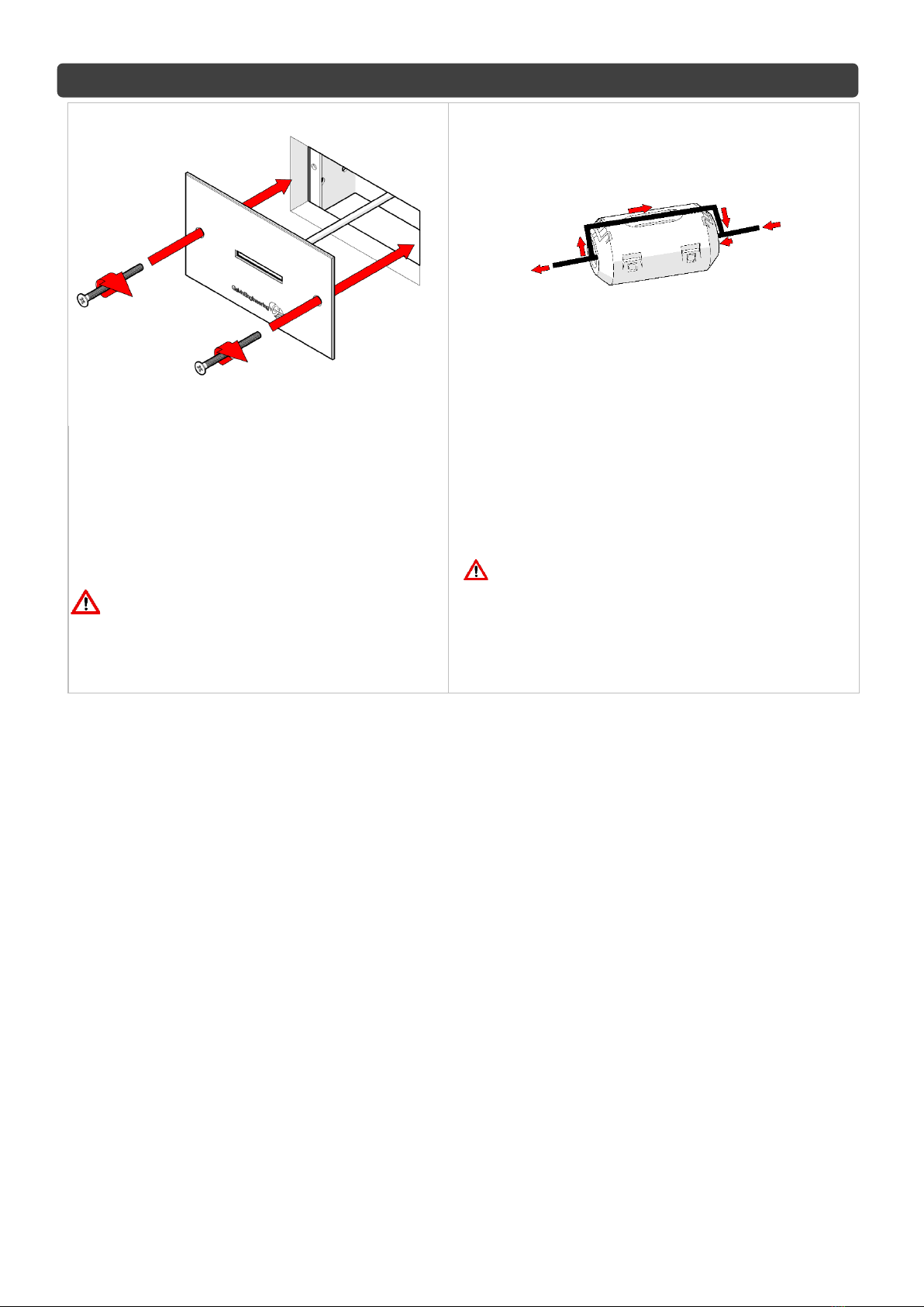
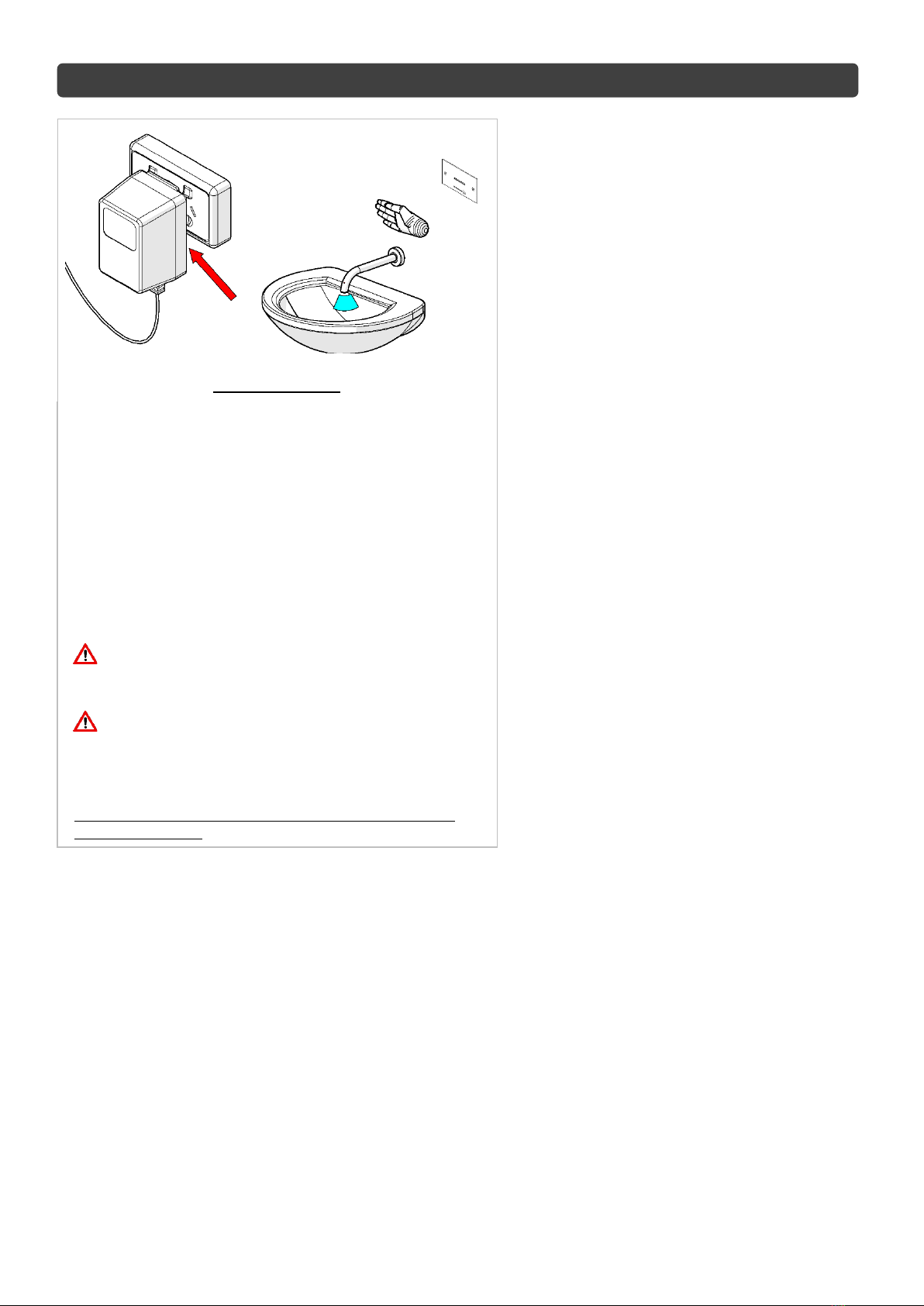
- Ensure that access to the sensor, solenoid valve and transformer/GPO is available for future maintenance when
installing the components. It is recommended that isolating valves be installed upstream to the solenoid valve to
allow for servicing. All wiring must be able to be removed when installed into cavities or walls, therefore, it is
recommended that a minimum of 25mm conduit be used to house the leads. The unit is supplied with 3 meters of
lead on the transformer and a 5 meters lead from the solenoid. Additional lead lengths may be accommodated up
to a length of 5m but must be ordered separately.
- Whilst our product designs take into account a broad range of installation types and surfaces, it is important that
surfaces which fixtures are mounted to are flat and free from defect. Additionally, ensure any protruding
connecting thread is square to the wall so that the outlet sits flat against the wall when installed. This is especially
important when installing product ranges that have been designed for correctional and health facilities, where
special attention is required to minimise ligature points and areas for concealment of contraband. In addition to
ensuring the products are fitted securely and in accordance with the following instructions, consideration shall be
given to the use of non-pick mastics such as BASF Sonolastic “Ultra” to ensure a high quality and safe
installation.
- Most installation problems are due to damage to the unit during installation or the selection of an inappropriate
installation location. Select the location carefully and take care with the installation, consider ease of operation for
the end user.
- It is advised that the sensor should not be positioned directly in front of reflecting surfaces, such as ceramic tiles,
stainless steel basins or mirrors. Any bright lighting reflecting off a highly reflective surface such as a stainless
steel basin, or a high visibility reflective vest, may interfere with correct sensor operation (Refer sensor settings
for operation and adjustment)
GENERAL INSTALLATION REQUIREMENTS
- Do not cut or extend the existing leads without using a correct lead extension from Galvin Specialised, as
this will void warranty.
- Suitable access to the service of all components must be provided.
- Do not apply heat near this product when connecting water lines. Heat generated by soldering could
damage plastic or electrical parts and seals, and will void the warranty.
- For personal installation assistance and spare parts, please call our head office on 1300 514 074 and
speak to our customer service staff.
COMPONENT DIMENSIONS
TZ-FLOWSENC24B - STAINLESS STEEL FACE PLATE WITH CONCEALED WALL SENSOR ASSEMBLY

© Galvin Engineering Pty Ltd
Version 2, 8 September 2021, Page 3of 10
Product Installation Guidelines
Version 1, 8 September 2021, Page 3of 10
INSTALLATION
Avoid common installation errors :
- Non-compliance to Australian Standards.
- No access for service.
1. Remove old face plate
- Remove the fixing screws and detach old face
plate from wall.
2. Connect new cable assembly to new sensor
−Connect the cable assembly to the rear of the Sensor,
observing the correct plug connection.

© Galvin Engineering Pty Ltd
Version 2, 8 September 2021, Page 4of 10
Product Installation Guidelines
Version 1, 8 September 2021, Page 4of 10
3. Mount new face plate
- Apply a thin bead of silicon on the edge of the
wall cut out.
- Fit the face plate using screws suitable for the
fixing method. (Fasteners to be supplied by
installer).
- If extension leads are required, please
contact Galvin Specialised.
Do not force the faceplate to fit onto wall
or attempt to disassemble components, as
this could result in damage to sensor.
4. Secure wiring with suppressor (not supplied)
−Connect electrical interference suppressor (not
supplied) to each cable (1x Transformer, 1x
Solenoid Lead) as shown and ensure they are as
close to the sensor face as possible
All electrical components should be protected
from contact with water or excessive heat and
installed in accordance with local regulations.

© Galvin Engineering Pty Ltd
Version 2, 8 September 2021, Page 5of 10
Product Installation Guidelines
Version 1, 8 September 2021, Page 5of 10
Typical Installation
5. Connect power supply & Check for correct operation
−The 24V AC transformer (not supplied) is plugged into a
standard mains power point (GPO).
−Turn on the power point and test the unit.
−Wave the back of your hand through the beam to turn
the water on and again to turn the water off.
−The sensor may require adjustment. Please ensure that
the sensor is in a position that reflects the actual
installation
Note: The sensor is factory set to medium and will
need to be adjusted to suit individual installations.
All electrical components should be protected
from contact with water or excessive heat and
installed in accordance with local regulations.
The connection of this product to mains power
supply should be undertaken by a competent
person and should conform to local Wiring
Regulation –AS3000 Wiring rules.
Note: For transformer supply and orders please contact
Galvin Specialised
(NOT SUPPLIED)

© Galvin Engineering Pty Ltd
Version 2, 8 September 2021, Page 6of 10
Product Installation Guidelines
Version 1, 8 September 2021, Page 6of 10
CONTROLL MODULE PROGRAM MODIFICATION
Required to make changes to the controller
settings :
- Android device (e.g. smartphone,
tablet).
- Installed from PlayStore ‘Flowmatic
system’ software. Locate and
download ‘Flowmatic Syatem’
software.
1. Establish Bluetooth connection
−Go to the Bluetooth settings on your device
then scan for devices. Generally, when
scanning the first thing to come up in
available devices will be a Mac address that
looks like this example (AB:EC:69:57:34:02).
This will eventually change to the name of
the device (This can be changed to a custom
name in the app).
−Select this device.
2. Entering the pin
- The device will ask for a pin, which from factory is
‘1234’. Enter this in. (This pin can be changed later
in the app.). Your device is now connected to the
controller, and is ready to be adjusted from the
‘Flowmatic system’ app.

© Galvin Engineering Pty Ltd
Version 2, 8 September 2021, Page 7of 10
Product Installation Guidelines
Version 1, 8 September 2021, Page 7of 10
3. Changing controllers settings
−Open the Flowmatic system’ app. The
device will appear on the screen. with Mac
Address first and then controller name e.g.
‘AB:EC:69:57:34:02 Flowmatic’.
−Select the Flowmatic, this will then update
the controllers time clock, and then open the
setting screen by pressing ‘Next’.
4. Setting screen overview.
−Upper function buttons. By pressing the ‘Get settings’
button the currently stored parameters in the
controller’s internal memory will be downloaded to the
app. The ‘Get log’ button will pop up the log data
screen. The ‘Presets’ button will list all saved presets.
−Drop-Down menus. First menu from left is to select
the type of controller the app is connected to. The
second menu is to select which ‘channel’ is going to
have parameters changed (only for PB2). The third
menu is to declare what is the controlled feature
designed for (only for PB2).
−Setting sliders. Depending on the selected controlled
feature there will appear one, two or three setting
sliders.
−Hygiene flush setting menu allows to set the time and
intervals of hygiene flush.
−Bottom function buttons are to be used to manage
the controller internal memory.

© Galvin Engineering Pty Ltd
Version 2, 8 September 2021, Page 8of 10
Product Installation Guidelines
Version 1, 8 September 2021, Page 8of 10
5. Type of controller (left drop-down menu)
- For the TZ-FLOWSENC24B controller the ‘Wave’ or
‘Proximity’ selection may be used depending on the
application. Please do not change the selection to
the , ‘Urinal’, ‘Pan’ ‘PB2’or ‘Flusher’.
6. ‘Wave’, ‘Proximity’ setting screens
contains the same setting parameters.
- Run time (s) slider –to set the required
flow time.
- ‘Detection threshold’ slider – to set
sensing range. By setting smaller value
the detection distance is farther. Bigger
value is making the detection distance
shorter.
7. Choosing the suitable mode
- ‘Wave’ mode:
•If a hand is detected, the water will start and keep flowing until the time set in the ‘Run time’ section will
pass or another ‘wave’ will appear in front of the sensor.
- ‘Proximity’ mode:
•If a hand is detected, the water turns on for as long as the hand is there, up to a certain timeout value set
in the ‘Run time’ section.
8. Settings ‘Hygiene flush’.
- Set the required time for Hygiene flush and press
‘Upload’.
9. Connection menu.
- By pressing the back arrow, the
connection screen will pop up.
The buttons allow to rename the controller,
set new PIN, disconnect, or go to setting
screen ‘Next’.

© Galvin Engineering Pty Ltd
Version 2, 8 September 2021, Page 9of 10
Product Installation Guidelines
Version 1, 8 September 2021, Page 9of 10
TROUBLE SHOOTING
PROBLEM
CAUSE
RECTIFICATION
Sensor Not
Responding
Damaged or scratched lens
Replace Sensor Unit
Sensor lead damaged
Replace sensor lead
No Power
Check power is reaching transformer
Waving Hand too fast past the sensor
Slow down the action in front of the sensor
Transformer faulty
Replace transformer
False
Activation
Electrical interference
Ensure electrical suppressors are installed
correctly
Reflection from a light source
Re-align sensor or shield light source
No water flow
Sensor not responding
Check fault relating to sensor
No power
Check power is reaching transformer
Power supply leads joined incorrectly
Replace electronic components
Faulty solenoid valve
Check electrical connections, Replace solenoid
valve
Water or structural damage to
electrical components
Replace damaged electrical components
Incorrect connections
Check all connections
Damage to sensor lead or power
supply lead
Check and replace lead & controllers
Pressure exceeding 500kPa
Reduce pressure to solenoid to 350 kPa
Water corroded electrical
connections
Replace electronic components
Continuous
water flow
Solenoid valve jammed open
Remove obstruction from solenoid valve
Solenoid installed incorrectly
Reinstall valve correctly
Note: Before attempting to replace any of these items check that you have access to re-run the
connection leads. If you do not have access or you have any doubts please contact Galvin Specialised for
advice before commencing replacement.
Optional modes:
- ‘Urinal’ mode:
•When a user is first detected in front of the sensor, the cycle is triggered so that a timer starts when the
user leaves. At the end of this timed period, the solenoid valve is actuated to flush the urinal and the cycle
is then reset.
- ‘Pan’ mode:
•When a user is first detected in front of the sensor, a timer starts. After a pre-set time, if the user is still
there, the sensor decides that a full flush will be required, otherwise, only a half flush will be triggered.
This flush happens a set time after the user leaves the immediate vicinity

© Galvin Engineering Pty Ltd
Version 2, 8 September 2021, Page 10 of 10
Product Installation Guidelines
Version 1, 8 September 2021, Page 10 of
10
MAINTENANCE INSTRUCTIONS
Sensor:
The Electronic Sensor is a non serviceable product. If damaged the sensor must be replaced.
−Turn power off at GPO.
−Unscrew the two fixing screws. The silicon seal may have to be cut with care to free the sensor.
−Unplug the solenoid plug and transformer plug from the rear of the sensor. Generally, if the sensor has been
damaged by an electrical surge, it is recommended that the transformer be replaced at the same time.
−Replace the sensor and reconnect the new sensor. Plug the solenoid and transformer plugs back onto the
rear of the sensor. Fix the sensor panel back onto the galvanised inwall box with the existing screws.
Important: Seal the stainless steel face panel and screws using silicon, ensuring it has a water tight
seal.
Note: Before attempting to replace any of these items check that you have access to re-run the
connection leads. If you do not have access or you have any doubts please contact Galvin Specialised for
advice before commencing replacement.
WARRANTY
The warranty set forth herein is given expressly and is the only warranty given by the Galvin Engineering Pty Ltd.
With respect to the product, Galvin Engineering Pty Ltd makes no other warranties, express or implied. Galvin
Engineering Pty. Ltd. hereby specifically disclaims all other warranties, express or implied, including but not
limited to the implied warranties of merchantability and fitness for a particular purpose.
Galvin Engineering Pty Ltd products are covered under our manufacturer’s warranty available for download from
www.galvinengineering.com.au Galvin Engineering Pty Ltd expressly warrants that the product is free from
operational defects in workmanship and materials for the warranty period as shown on the schedule in the
manufacturer’s warranty. During the warranty period, Galvin Engineering will replace or repair any defective
products manufactured by Galvin Engineering without charge, so long as the terms of the Manufacturer’s warranty
are complied with.
The remedy described in the first paragraph of this warranty shall constitute the sole and exclusive remedy for
breach of warranty, and Galvin Engineering Pty Ltd shall not be responsible for any incidental, special or
consequential damages, including without limitation, lost profits or the cost of repairing or replacing other property
which is damaged if this product does not work properly, other costs resulting from labour charges, delays,
vandalism, negligence, fouling caused by foreign material, damage from adverse water conditions, chemical,
electrical or any other circumstances over which Galvin Engineering has no control. This warranty shall be
invalidated by any abuse, misuse, misapplication, improper installation or improper maintenance or alteration of
the product.
Table of contents
Other Galvin Engineering Accessories manuals

Galvin Engineering
Galvin Engineering CliniMix Lead Safe 100.30.79.00 Instruction sheet

Galvin Engineering
Galvin Engineering CliniMix CMV2 Instruction sheet

Galvin Engineering
Galvin Engineering Flowmatic TZ-IQWAVEB User manual

Galvin Engineering
Galvin Engineering CliniMix CMV2 Instruction sheet

Galvin Engineering
Galvin Engineering CliniMix CMV2 Instruction sheet

Galvin Engineering
Galvin Engineering CliniMix CMV2 Instruction sheet