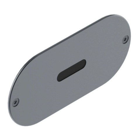
Galvin Engineering CliniMix Lead Safe 100.30.79.00 Instruction sheet

1
Version 2, 21 August 2019, 1 of 21
CliniMix®Lead Safe™ Wall Mounted Thermostatic
Progressive Basin Mixer - Proximity Sensor
PRODUCT CODE:
- 100.30.79.00
TABLE OF CONTENTS
1.0 INTRODUCTION 1
2.0 SAFETY 2
3.0 DESCRIPTION 2
4.0 DIMENSIONS 2
5.0 WATER SUPPLY CONDITIONS 3
6.0 INSTALLATION 4
7.0 COMMISIONING 7
8.0 OPERATION 10
9.0 SERVICING 10
10.0 MAINTENANCE 12
11.0 DISINFECTION 14
12.0 ISOLATING VALVES 15
13.0 WARRANTY 16
14.0 TROUBLESHOOTING 17
15.0
APPENDIX
18
1.0 INTRODUCTION
The CliniMix® Wall Mounted Thermostatic Progressive Basin Mixer - Proximity Sensor
is a high-performance thermostatic mixing valve suitable for a wide range of applications. The valve is
- Materials, Design and Performance
−Complies with the requirements of AS4032.4 Thermostatic Mixing Valves.
−Provides high stability of mixed water temperature even under changing inlet conditions.
−Ensures rapid shut down of mixed outlet flow in the event of hot or cold water supply failure.
−Designed for quick and simple in-situ servicing.
−Suitable for installation into AS3500 compliant systems with hot water temperature as low as 55°Celsius.
−Fitted with tamper resistant temperature adjustment mechanism.
−Cool touch, non-conductive design in the hot side of the body, which minimises the risk of burns.
−Round smooth design to facilitate easy cleaning.
−Self-draining spout design.
−Unique hygiene flush feature for in-situ disinfection.

2
Version 1, 21 August 2019, 2 of 21
2.0 SAFETY
The CliniMix®Thermostatic Progressive Mixing Valve is a high-performance valve designed to give stable
and dependable operation, provided it is installed, commissioned, operated and maintained as per the
recommendations outlined in this manual. It should be noted however that this valve should not be
considered as an alternative to adequate supervision and duty of care during its use and operation.
Note: The mixing valve, inlet controls, pipe work and the surrounding area may become hot when
installed which may cause burn injuries. Precautions should be taken to ensure that these surfaces
cannot cause such injuries.
3.0 DESCRIPTION
This manual covers the CliniMix®Wall Mounted Thermostatic Progressive mixers with proximity sensor.
These are designed to provide water in stable temperature for hand washing. This mixing valve is supplied
with integral isolating valves, strainers, check valves and flow regulators and is provided with a facility for
thermal disinfecting of the cold inlet side and mixed water outlet for the wall mounted version only.
The hot side of the body and the inlet is insulated to ensure the body surface is maintained at a safe
temperature when the fitting is in operation.
Avoid using heat for soldering near the mixer inlets to prevent damage to internal components.
4.0 DIMENSIONS
−The rough in details have been provided to show
correct fitment of the Progressive Mixer (see below
image).
−A cavity must be supplied to fit sensor on the back
of faceplate as shown, minimum 20mm deep.
−Drill 2 x mounting 6.0x30 deep holes, location as
shown.
Note: Maximum spud length to be 15mm. See
below image position of sensor from basin.
TYPICAL INSTALLATION VIEW

3
Version 1, 21 August 2019, 3 of 21
4.1 TECHNICAL DATA
Inlet
Female
Outlet
Flow Straightener
Headwork
Thermostatic mixing valve
Mains Powered (Transformer)
Input
90 264V - 47/63Hz 0.15A
Output
6.75V DC 0.5A
Cable length
0.7m
Battery Powered
N/A
Solenoid
Input Voltage
6.75V DC
Power Consumption
-
Cable length
3.2m
Connection
Inlet
- Female
Outlet
- Male
Pressure Range
(kPa)
Min
30
Max
1000
Temperature (°C)
Min
5
Max
80
Finish
Chrome
NOTE: Galvin Specialised continually strive to improve their products. Specifications may change without
notice.
Table 1. Technical information
4.2 SENSOR DETAILS
•Hardware
Varox 4.2.2
•Software
IQ7VARIR2V 7.15-0256, release 15.5.2015
•Input Voltage
6.75V DC 0.5A
•Cable length
3.2m
•Sensor function
Standard washbasin (with proximity sensor)
•Preset line purge feature interval:
12 hours after last flush, water flow duration 3 min
•Preset continuous run:
5 min
•Sensor range:
Sensor1 and Sensor2 custom made steps
5.0 WATER SUPPLY CONDITIONS
5.1 INTRODUCTION
This progressive sequential thermostatic mixer with proximity sensor is manufactured to the highest
standards and has approval to AS4032.4 which permits it to be installed in healthcare establishments such
as hospitals, nursing homes and residential care homes. When installed in healthcare establishments the
supply conditions detailed in Table 2 must be observed and the commissioning and servicing requirements
detailed on section 6 & 8 must be followed.
5.2 SUPPLY PRESSURE REQUIREMENTS
This mixer is designed to be installed on all types of plumbing systems.
Hot and cold water supply pressures should be reasonably balanced; however, the mixer will function within
specification on unequal pressures up to 10:1.

4
Version 1, 21 August 2019, 4 of 21
The mixer has integral isolating valves which permit servicing of the strainer, check valve/flow regulator and
thermostatic cartridge. They are also used for thermal disinfection.
The minimum pressure for the correct thermal operation is 20kPa. However, to achieve an acceptable flow
performance at very low pressures it may be necessary to remove the combined check valve and flow
regulators and replace them with simple check valves to facilitate thermal disinfection.
Working Temperature Range (°C)
Min
5
Max
85
Minimum Temperature Differential (between the supply and the outlet temperature) (°C)
Min
10
Adjustable Temperature Range (°C)
Min
35
Max
48
Working Pressure Range (kPa)
Min
20
Max
500
Permitted Supply Pressure Variation
10:1
Factory Set Thermostatic Temperature (°C)
41
Maximum Thermostatic Temperature (°C)
48
Minimum Flowrate for Stable Outlet Temperature (LPM)
6
Nominal Flowrate (LPM)
8
Table 2. Water supply conditions
Note: Tapware must be installed in accordance with the provisions of AS/NZS 3500. Installations not
complying with AS/NZS 3500 may void the product and performance warranty provisions.
6.0 INSTALLATION
The CliniMix®Thermostatic Progressive Mixing Valves must be installed using the appropriate Standard,
Code of Practice and legislation application to each state and following the details outlined in this section.
The CliniMix®Thermostatic Progressive Mixing Valves must be installed by a licensed plumber, or where
applicable, a licensed plumber who has undertaken T.A.F.E. training in Thermostatic Mixing Valves.
Note: To effectively control microbial hazards during system design, installation, commissioning and
maintenance, the requirements outlined in AS/NZ3666 and local legislation shall be adhered to.
If the valve is not installed correctly then it will not function correctly and may put the user in danger. It may
also void the warranty of the valve.
Prior to the installation of the valve, the system must be checked to ensure that the system operating
conditions fall within the recommended operating range of CliniMix®Progressive Thermostatic Mixing Valve.
If the hot water supply temperature is greater than 90° Celsius, the valve may be damaged. If the
temperature of the hot water will rise above 90° Celsius a suitable temperature limiting valve must be fitted to
the hot water supply, prior to the inlet fittings. This temperature limiting valve must be installed as per the
instructions. It is important that both inlet dynamic supply pressures are 500kPa or less. If
either supply pressure exceeds 500kPa then a suitable pressure reducing valve must be fitted prior to the
inlet control valve to reduce the pressure to an acceptable limit.
These pressure reducing valves must be installed as per the instructions. To achieve optimum
performance from the valve it is recommended that the inlet pressures are balanced to within 10% of each
other.
The water quality conditions should be checked to ensure they do not exceed the limits as listed in AS3500.4,
Section 3.7.1. If they do exceed these limits, then it will be necessary to install a water softener or water
treatment device.
INSTALLATION COMPLIANCE: Galvin Specialised products must be installed in accordance with these
installation instructions and in accordance with AS/NZS 3500, the PCA and your local regulatory requirements.
Water and/or electrical supply conditions must also comply to the applicable national and/or state standards.
Failing to comply with these provisions shall void the product warranty and may affect the performance of the
product.

5
Version 1, 21 August 2019, 5 of 21
1. Fit isolator connector
−
supply outlets are positioned as per
mounting details (section 4.0) at the
desired height and location above the
basin/sink.
Note: Hot supply should be on the left
when facing the wall
Remove both isolator connectors from
box.
−Remove chromed sleeve from the
connectors
−Apply thread tape to the male threaded
outlets and fit the isolator connectors.
2. Adjust the connectors
−The isolator connectors are offset to provide +/-
15mm of rotational adjustment.
−With the use of a spirit level and tape measure, you
are required to
▪Position the back of the bases within 3mm of
the finished wall and;
▪Ensure the bases are level and;
▪Achieve 200mm centre to centre of the
connectors
Note: The use of thread tape is recommended to
ensure bases stay in the required position and are
water tight.
3. Fit progressive mixer
−Fit chrome sleeves to fitted isolator
connectors.
Tighten loose nuts on the body to the isolator
connectors already on the wall ensuring the
strainer seal is in between. Do not over
tighten.
4. Secure Sensor
−Install the proximity sensor to the wall
−Ensure correct orientation of the sensor, It is
critical (see back of the face plate for orientation
arrow)
Do not remove the black label in front of sensor
faceplate until the tap is to be commissioned.
5. Fit solenoids
−Connect solenoids to the tap and mains
water line
Ensure water is connected to correct inlet as
marked on tap.
6. Connect solenoids
−Connect the solenoids to the sensor.
The unit supplied with a 3 x 3.2metre extension leads for
connecting to transformer, solenoid, and sensor.
Table of contents
Other Galvin Engineering Accessories manuals

Galvin Engineering
Galvin Engineering CliniMix CMV2 Instruction sheet

Galvin Engineering
Galvin Engineering CliniMix CMV2 Instruction sheet

Galvin Engineering
Galvin Engineering CliniMix CMV2 Instruction sheet

Galvin Engineering
Galvin Engineering Flowmatic TZ-FLOWSENC24B User manual

Galvin Engineering
Galvin Engineering CliniMix CMV2 Instruction sheet

Galvin Engineering
Galvin Engineering Flowmatic TZ-IQWAVEB User manual