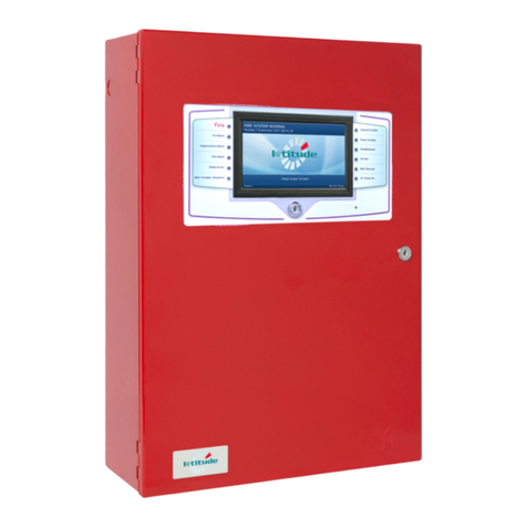
technoswitch DP-PSUEN Series User manual

DP-PSUEN Series Installation & Operation Manual Rev 11.1 220323.docx
DP-PSUEN
EN54-4 Fire Alarm Power Supply Series
Rev 11.1

DP-PSUEN EN54-4 Fire Alarm Power Supply Series –INSTALLATION & OPERATION MANUAL
DP-PSUEN Series Installation & Operation Manual Rev 11.1 220323.docx E&OE
- 2 -
CONTENTS
1GENERAL ____________________________________________________________________________ 3
1.1 Product Range ___________________________________________________________________ 3
1.2 Features_________________________________________________________________________ 3
2ELECTRICAL AND OPERATIONAL SPECIFICATIONS ________________________________________ 3
3COMPLIANCE _________________________________________________________________________ 4
4POWER SUPPLY PHYSICAL DIMENSIONS AND FEATURES __________________________________ 5
4.1 Large Box _______________________________________________________________________ 5
4.2 Medium Box _____________________________________________________________________ 6
4.3 Printed Circuit Board ______________________________________________________________ 7
5INSTALLATION AND OPERATION ________________________________________________________ 7
5.1 Mounting ________________________________________________________________________ 7
5.2 AC Power Connection and Wiring ___________________________________________________ 8
5.3 Jumper Links ____________________________________________________________________ 8
5.4 LED Display______________________________________________________________________ 9
5.5 OP1 and OP2_____________________________________________________________________ 9
5.6 SWI and SW2 Inputs_______________________________________________________________ 9
5.7 DATA and LED Interfaces __________________________________________________________ 9
5.8 Fault Detection and Outputs ________________________________________________________ 9
5.9 Batteries _______________________________________________________________________ 10
5.9.1 Battery Temperature Remote Sensor Fitting____________________________________________ 11
5.9.2 Battery Protection ________________________________________________________________ 11
5.9.3 General Maintenance _____________________________________________________________ 11
6DECLARED PERFORMANCE ___________________________________________________________ 12
7ORDERING INFORMATION _____________________________________________________________ 12
8WARRANTY __________________________________________________________________________ 13
9DISCLAIMER _________________________________________________________________________ 13
10 REVISION INFORMATION ______________________________________________________________ 13

DP-PSUEN EN54-4 Fire Alarm Power Supply Series –INSTALLATION & OPERATION MANUAL
DP-PSUEN Series Installation & Operation Manual Rev 11.1 220323.docx E&OE
- 3 -
1GENERAL
1.1 PRODUCT RANGE
The DP-PSUEN series of product consists of the following products:
▪DP-PSUEN1.5 EN54 24(27.6)VDC 1.5 Amp PSU, Space for 2x 7Ah batteries
▪DP-PSUEN3-L EN54 24(27.6)VDC 3.0 Amp PSU, Space for 2x 17Ah batteries
▪DP-PSUEN3-S EN54 24(27.6)VDC 3.0 Amp PSU, Space for 2x 7Ah batteries
▪DP-PSUEN5 EN54 24(27.6)VDC 5.0 Amp PSU, Space for 2x 17Ah batteries
The power supplies can be supplied in either a medium or large box which can house 7Ah or 17AH batteries
respectively.
1.2 FEATURES
The DP-PSUEN series of power supplies are designed to be used for fire alarm control and indicating equipment
complying with EN54-2 and EN54-4.
The power supply range consist of a 5 amp, 3 amp and 1.5 amp devices, providing a nominal 27V with two 12V
lead acid batteries for standby operation without AC power. The power supplies share the following features:
▪Microprocessor controlled operation and protection
▪On-demand battery charging and load output current sharing
▪Automatic output reconnection after short circuit fault
▪No user serviceable fuses, outputs protected by electronic E-fuses
▪Two independent switched outputs with programmable (jumper selectable) control inputs
▪On board or remote temperature sensing (jumper selectable) with optional remote sensor
▪Separate AC healthy, battery fault and power supply fault outputs
▪Three fault outputs, AC Power Fail, Battery Fault, PSU Fault
▪Form A, normally closed floating relay fault outputs
▪Four LED status display
▪Over-voltage output protection
▪Battery-free option selected by a jumper
The on-demand load sharing capability gives the power supply range exceptional flexibility. This allows rapid large
capacity battery charging with either extended standby hold-up duration at light loads, or short high current peak
loads where spare output capacity is diverted to battery charging.
2ELECTRICAL AND OPERATIONAL SPECIFICATIONS
SPECIFICATIONS
AC Input Voltage
230VAC ±10%, 50Hz.
Maximum Input Continuous
Current
DP-PSUEN5, 1.5A
DP-PSUEN3, 0.9A
DP-PSUEN1.5, 0.45A
Peak inrush current limit
20A maximum.
Recommended Switched Spur
Input Fuses
DP-PSUEN5, 250V T3.15A
DP-PSUEN3, 250V T3.15A
DP-PSUEN1.5, 250V T1A
Voltage Output AC Present
Minimum 25.0Vdc, Maximum 28.5Vdc.
Voltage Output Standby
Minimum 20Vdc, 24 V Nominal
Total Continuous Output Current
(Imax.b)
DP-PSUEN5, 5A
DP-PSUEN3, 3A
DP-PSUEN1.5, 1.5A
Current output with battery
charging (Imax.a)
DP-PSUEN5, 4.3A
DP-PSUEN3, 2.3A
DP-PSUEN1.5, 1.2A

DP-PSUEN EN54-4 Fire Alarm Power Supply Series –INSTALLATION & OPERATION MANUAL
DP-PSUEN Series Installation & Operation Manual Rev 11.1 220323.docx E&OE
- 4 -
SPECIFICATIONS
Battery Charging Current
On demand. Maximum.
DP-PSUEN5, 5A,
DP-PSUEN3, 3A,
DP-PSUEN1.5, 1.5A
Low Voltage detection thresholds
<22V ±2%, low voltage restore, >23V ±2%.
Battery Circuit Impedance
Threshold (Ri max)
>0.18 Ohm ±5%, at a nominal test current of 5A.
Deep Discharge Disconnection
Threshold
<21V ±2%.
Overvoltage Detection Shutdown
Threshold
>30V ±2%.
Output Monitoring Threshold
Battery charging voltage <2V ±2%.
On-Board AC Power Input Fuses
DP-PSUEN5, T3.15A
DP-PSUEN3, T3.15A
DP-PSUEN1.5; T1A timed
All non-replaceable.
Battery Fuse
PTC, self-resetting, non-replaceable.
Fault Relays
Normally closed, 100mA at 60V. On-Resistance 16 ohms
maximum, 1500VRMS Isolation voltage
PSU Standby Current
32mA.
Maximum Ripple Voltage
0.7V peak to peak.
Battery Type
Sealed Lead Acid Gel, YUASA NP7-12F/RETARD, YUASA
NP17-12F/RETARD, YUASA NP7-12, YUASA NP17-12I
Operating Temperature and
Humidity Range
-10oC to +40oC, 95% maximum humidity, non-condensing
Minimum Output Current
(I min)
200mA for all DP-PSUEN series
Battery current drawn by power
supply without AC supply
Maximum 55mA (Depending on fault output status)
3COMPLIANCE
The power supplies comply with the following European Directives:
Low Voltage: 2006/95/EC
EMC: 2004/108/EC
WEEE: 2012/19/EU
RoHs: 2011/65/EU
IEC61140: Protection against electric shock –Common aspects for installation and equipment:Class 1
EN54-4: 1997 + A1 + A2 Part 4:Power Supply Equipment
0359

DP-PSUEN EN54-4 Fire Alarm Power Supply Series –INSTALLATION & OPERATION MANUAL
DP-PSUEN Series Installation & Operation Manual Rev 11.1 220323.docx E&OE
- 5 -
4POWER SUPPLY PHYSICAL DIMENSIONS AND FEATURES
4.1 LARGE BOX
Dycon Ltd
D2435 PSU
INPUT
230V ; 1.5A
50Hz
OUTPUT
24V 5A
12.00
50.00
50.00 50.00
390.00
184.00
60.00
128.00
195.00
97.50
Ø20.00
Knockout
Knockout
Knockout
Knockout Knockout
Knockout
Knockout
Knockout
Knockout
Knockout
Overall dimensions including lid are 394.5mm x 379mm x 90mm
Side knockout centres are 46.5mm above mounting surface, top and bottom
knockouts are 50mm above mounting surface.
375.00
Knockout
51.00
36.00
36.00
36.00 36.00
Knockout
290.00
274.00
First fix keyhole
mounting slot
Mounting
Hole
Mounting
Hole
PCB mounting
pillars x 4
LED light pipe
mounting
bracket
Case earth
stud
110.00
145.00
Rating
Label

DP-PSUEN EN54-4 Fire Alarm Power Supply Series –INSTALLATION & OPERATION MANUAL
DP-PSUEN Series Installation & Operation Manual Rev 11.1 220323.docx E&OE
- 6 -
4.2 MEDIUM BOX
Overall dimensions including lid are 329.5mm x 294mm x 85mm
Side knockout centres are 44mm above mounting surface, top and bottom
knockouts are 45mm above mounting surface.
50.00
50.00 50.00
330.00
60.00
126.50
Ø20.00
Knockout
Knockout
Knockout
Knockout
Knockout
Knockout
290.00
Knockout
180.00
56.00
Knockout 135.00
165.00
230.00
184.00
First fix keyhole
mounting slot
Mounting
Hole
Mounting
Hole
LED light pipe
mounting
bracket
PCB mounting
pillars x 4
Case earth
stud
Dycon Ltd
D2433 PSU
INPUT
230V ; 900mA
50Hz
OUTPUT
24V 3A
106.75
65.00
Rating
Label

DP-PSUEN EN54-4 Fire Alarm Power Supply Series –INSTALLATION & OPERATION MANUAL
DP-PSUEN Series Installation & Operation Manual Rev 11.1 220323.docx E&OE
- 7 -
4.3 PRINTED CIRCUIT BOARD
All three power supplies have a very similar form, fit and function, the dimensions are identical. The DP-PSUEN5 is
shown as an example below. NOTE: Plastic cage is not fitted on the DP-PSUEN5 power supply:
168.00
141.00
145.00 6.00
10.007.00
129.50
6.00 5.50
Power DCstatus LED, yellow: Indicates
that DC power is available
ACOKled, green: Indicates
availability of external AC power
Battery Fault, yellow: Indicates
if any battery faults are present
PSU Fault, yellow: Indicates
any power supply system faults
are present
Battery
Connectors
Nominal 24V
output 2 to load
Nominal 24V
output 1 to load
3.2mm Mounting Holes x 5
Live AC power connection
Caseand earth connection tab
Protective earth connection
Neutral AC power connection
SW1 and SW2 control inputs
inversion jumper
Battery-free operation jumper
Optional external temperature
sensor connector
On-board temperature sensor
disable jumper
24V output switching control
inputs with 0V return
External Power Supply (ACpower)
faultnormally closed relay output
Serial data interface
External LEDinterface
Auxiliary Power Supply (battery)
faultnormally closed relay output
Power Supplyfault normally
closed relay output
Plastic safety cage
5INSTALLATION AND OPERATION
NB: WARNING: Isolate the AC power supply before working on the power supply. Only suitably qualified
personnel should install these power supplies and wiring should comply with the latest edition of IEE
Wiring Regulations (BS 7671) or local national electrical standards.
5.1 MOUNTING
The power supplies are designed for indoor use, within the specified operational temperature and humidity limits.
The metal enclosures should be mounted on a solid, flat and dry surface using the three mounting points provided.
The screws should have a minimum shank diameter of 5mm (No 11 gauge) and use suitable wall plugs where
needed.

DP-PSUEN EN54-4 Fire Alarm Power Supply Series –INSTALLATION & OPERATION MANUAL
DP-PSUEN Series Installation & Operation Manual Rev 11.1 220323.docx E&OE
- 8 -
When a final sighting for the power supply has been decided it is highly recommended that the 20mm knockouts
that are going to be used are removed before fitting the box by a sharp tap with a hammer and flat bladed
screwdriver at the edge of the knockout. Separate knockout holes should be used for AC power entry and low
voltage wiring and the wiring kept apart. The knockout holes are designed to accept cable glands.
The power supplies should not be mounted near sources of heat or moisture and should be accessible for ease of
fitting heavy batteries.
The printed circuit assembly will have to be removed from the medium sized enclosure before mounting. This is
done by pushing the four light pipes towards the lid until they unclip, removing the earth lead by pulling the earth
connector off the tab and unscrewing the four board securing screws. The printed circuit assembly can then be
removed before mounting.
The keyhole slot at the top of the enclosure may be used as a first fix to hang the unit where the bottom two holes
can be marked off when level and then removed for drilling. Using the enclosure directly as a drilling template
should not be done as it risks dust damage.
Care should be taken when refitting the board using the shake proof washers and ensuring they are tight to make
good electrical contact with the printed circuit board and the metal base. The light pipes can then be clipped back
into place and that they are positioned over the LEDs. The earth cable can then be pushed back on to the
connector tab.
5.2 AC POWER CONNECTION AND WIRING
AC power with a protective earth for Class 1 equipment is to be used with an isolating switched spur using the
recommended fuse ratings or a fuse rating of not greater than 5A. The fused switched spur should be fitted as
close to the power supply as practicable to allow isolation when the unit is serviced. AC power cable with
conductors of a cross sectional area greater than 0.75mm should be used.
The AC power cables shall be segregated from the low voltage control wiring and outputs to load. 20mm diameter
knockouts on the four sides of the box are provided for cable glands including mineral insulated copper-clad cable.
Where batteries are fitted, the knockouts at the bottom of the box will not be available.
To comply with EN54 requirements both AC power and low voltage wiring must use cable glands to meet IP30
enclosure protection standards.
5.3 JUMPER LINKS
NB: WARNING: The AC power supply and the batteries must be disconnected before the jumper
positions can be changed. Failure to do so can cause damage to the PSU, batteries and connected
equipment.
The power supply must not be used with the INT jumper in the off position without a DP-PSUEN
external temperature sensor fitted, as this could result in a battery fire or explosion risk.
The NO BAT link must be in the off position to comply with EN54-4 requirements.
Three jumper links are provided for configuring the PSU, the “off” position is when the jumper is “parked” on a
single pin and the “on” position is when the jumper is placed across two pins:
JUMPER
DEFAULT
OPERATION
INV
(Invert inputs)
Off
(Not inverted)
When left in the off position the outputs associated with the SW1 and
SW2 inputs will be switched on when they are at a logic high. When in the
on position the outputs associated with the SW1 and SW inputs will be
switched off when they are at a logic high.
NO BAT1
(Battery free
operation)
Off
(Battery
monitoring
enabled)
With the jumper left in the off position, the PSU will operate as normal with
battery standby when AC power is not available. If operation without a
battery being fitted is required, then the jumper should be in the on
position.
INT2
(Internal/external
temperature
sensing)
ON
(Internal
temperature
sensing)
When the jumper is fitted the PSU will use the internal on-board
temperature sensor, the link must be put into the off position to use an
external temperature sensor.

DP-PSUEN EN54-4 Fire Alarm Power Supply Series –INSTALLATION & OPERATION MANUAL
DP-PSUEN Series Installation & Operation Manual Rev 11.1 220323.docx E&OE
- 9 -
NOTES
1. This jumper can also be used to supress a battery fault condition until a new battery can be fitted. The jumper
disables the battery monitoring only and allows the battery to be charged and provide standby power as normal.
NOTE: Disabling the battery monitoring with a battery fitted will cause an EN54-4 non-compliance.
2. The power supply must not be used with the jumper in the off position without a DP-PSUEN external temperature
sensor fitted, as this could result in a battery fire or explosion risk.
5.4 LED DISPLAY
Four board-mounted LEDs are used to provide a status and fault display. These
LEDs are brought out to the lid via light pipes and identified with the label as shown.
24 VDC OUTPUT ON: The yellow LED indicates that DC power is available.
AC INPUT ON: The green LED is lit when AC power is available.
BATTERY FAULT: The yellow LED is lit when any battery related faults are
detected.
PSU FAULT: The yellow LED is lit when any power supply related faults
are detected.
5.5 OP1 AND OP2
Due to high instantaneous current that can flow under fault conditions, the DC output wire is recommended to be
1mm cross sectional area or greater for all DP-PSUEN series power supplies.
The outputs are individually protected against short circuits. The outputs can be switched using the SW1 and SW2
output control inputs. The outputs are fully protected against switching transients and are suitable for switching
highly inductive loads such as door strikes and magnets.
The combined output current of the two outputs must not exceed the power supply ratings.
5.6 SWI AND SW2 INPUTS
These inputs can be used to switch on and off their associated outputs. The polarity of these inputs are selected by
the INV jumper, with the jumper in the off position the outputs can be switched off when the input is low and when
in the on position (inverted) the output can be switched off with a positive input.
The wiring to these inputs shall not be more than 3 meters in length.
The inputs have a 100K pull-up resistor and are 30V tolerant. They are designed to be easily driven by a 5V logic
output, relay contacts or open collector transistors, see drive examples below:
100K
5V
INV in off position, output
switched off when
transistor conducts
100K
5V
INV in on position, output
switched on when
contacts close
100K
5V
INV in off position, output
switched on when
contacts open
SW1SW2
Internalpull-up
SW1
Internalpull-up Internalpull-up
5.7 DATA AND LED INTERFACES
These interfaces are used for factory testing and are reserved.
5.8 FAULT DETECTION AND OUTPUTS
Three normally closed relay outputs in no-fault conditions are provided for fault signalling and will open when a fault
is detected. The PSU is factory fitted with two wire links as shown below. To comply with EN54 requirements the
three separate normally closed fault outputs should be connected in series, so should any one of the fault relays
opens in a fault condition, a generic fault condition is signalled.

DP-PSUEN EN54-4 Fire Alarm Power Supply Series –INSTALLATION & OPERATION MANUAL
DP-PSUEN Series Installation & Operation Manual Rev 11.1 220323.docx E&OE
- 10 -
AC
FLT BAT
FLT PSU
FLT
Wire Links
Normally Closed
Generic Fault
Output
The table below shows the relation between fault and outputs.
FAULT
OUTPUT
DISPLAY
DESCRIPTION
AC power
missing
AC
Fault
DC Power
AC Power
The front panel DC power LED will be on to indicate that DC is
available, with or without AC power, The internal AC power LED
will be off.
OP1 or OP2
shorted
PSU
Fault
PSU
The outputs will automatically retry to restore power every 5
seconds until the short is removed.
Over-
voltage1
PSU
Fault
PSU
If the power supply voltage exceeds 30 volts, both outputs will be
switched off and a latched fault generated2.
Battery
connection
fault
BAT
Fault
Battery
If any of the battery connectors are disconnected a battery fault
will be generated.
Battery high2
resistance
fault
BAT
Fault
Battery
The battery or battery connections are tested every hour and if the
resistance is over 0.18ohms, a fault is generated4.
PSU low
voltage
PSU
Fault
PSU
If the internal PSU power rail voltage is too low to charge the
battery, a fault will be generated5.
PSU
Failure
PSU
Fault
PSU
Should the switching power supply fail due to overloading, over-
temperature or a component failure, a fault will be generated.
Charging3
Failure
PSU
Fault
PSU
Should the charging circuit fail, then a fault will be generated.
Battery Low
Fault
APS3
Fault
Battery
If any individual battery is left to discharge below 11.5V when the
PSU is in standby mode, a fault will be generated.
NOTES
1. Over voltage protection is done at two levels, the first being where the internal power low voltage rail (nominal
24V) is monitored and the second is where the off-line, high voltage side of the switched mode power supply is
monitored. Should an off-line fault be found then the high voltage switching circuit will be disabled. In both
conditions the power supply should be switched off and the batteries removed for 15 minutes to reset the fault.
2. The battery and connection resistance is tested every hour, except when first powered up. On power-up the
battery is tested after 5 minutes to alert the installer to any potential battery condition fault. The fault threshold is
approximately 0.18 Ohm.
3. This fault condition is detected by comparing the internal rail voltage to the calculated temperature compensation
voltage. If more than 1 volt lower, then a fault will be generated.
5.9 BATTERIES
NB: WARNING: There is a risk of fire and explosion if the wrong batteries or battery connection cables
are fitted. Care should be taken with polarity when connecting the batteries. Used batteries should be
disposed of in accordance to the WEEE directive.
Two identical batteries of the specified type shall be used, preferably from the same batch and date of
manufacture. This is important to maintain a balance of charge between the two batteries. Two cable harnesses
are provided for individual connection to the board, where they are connected in series. The remote temperature

DP-PSUEN EN54-4 Fire Alarm Power Supply Series –INSTALLATION & OPERATION MANUAL
DP-PSUEN Series Installation & Operation Manual Rev 11.1 220323.docx E&OE
- 11 -
sensor as supplied is to be fitted between the batteries. The size of the batteries is dependent on the size of the
box, the load current and the amount of standby time required. The medium box will house two 7Ah batteries and
the large box two 17Ah batteries. The battery cables are to be segregated from the incoming AC power supply
wiring.
5.9.1 Battery Temperature Remote Sensor Fitting
A remote battery sensor is supplied for accurate temperature compensation to comply with EN54-4 requirements.
The sensor is plugged into the TEMP 3-way socket and the EXT jumper must be removed to enable the sensor.
The sensor is supplied with a 200mm lead so the sensor head can be fixed between the batteries with a self-
adhesive fixing plate and ty-wrap as provided. The power supply is not to be used with the EXT Jumper link
removed without a remote temperature sensor fitted.
5.9.2 Battery Protection
The batteries are reverse connection protected and the battery charging output is protected from short circuits.
The battery output is overload protected by a resettable fuse, in addition to the electronic output fuses. If this fuse is
tripped then the batteries should be disconnected for 5 minutes to allow the fuse to reset.
When in standby mode the battery is switched off when the battery terminal voltage reaches 20V to prevent battery
deep discharge damage. This fault is normally reset by restoring the AC power supply.
5.9.3 General Maintenance
NB: WARNING: Isolate the AC power supply before removing the power supply lid. Do not touch
components or heat sinks as there is risk of electric shock or burn hazard.
The power supply should be regularly inspected by qualified personnel and the following checked:
1. No faults are displayed.
2. Battery terminals checked for corrosion and the terminals are securely tightened.
3. All the connections into the power supply terminal blocks are secure.
4. The battery voltages are checked and the voltages are balanced within a volt to each other. The battery
manufacturer’s specifications should be consulted when making battery voltage measurements.
5. Battery replacement is recommended after a 5-year service life.
6. Check there are no signs of water or moisture ingress and there is no mechanical damage to the enclosure.
7. Check for signs of overheating on the power supply board and battery cases.
8. Check the voltage outputs, they should be nominally between 26.5V and 28.5V depending on temperature.
9. There are no replaceable input, battery or output fuses. In the event of a fault the power supply board will have
to be replaced.

DP-PSUEN EN54-4 Fire Alarm Power Supply Series –INSTALLATION & OPERATION MANUAL
DP-PSUEN Series Installation & Operation Manual Rev 11.1 220323.docx E&OE
- 12 -
6DECLARED PERFORMANCE
0389
Dycon Power Solutions Ltd, Unit A, Cwm Cynon Business Park, Mountain Ash, CF45 4ER, UK
14
D2431, D2433, D2435/2014/09/19
Harmonised Technical Specification
EN54-4:1997 + A1:2002
+ A2:2006
Essential Characteristics
Performance
Clause
Performance of power supply
- - General requirements
- - Functions
- - Materials, design and manufacture
Pass
Pass
Pass
4
5
6
Operational reliability
- - General requirements
- - Functions
- - Materials, design and manufacture
- - Documentation
- - Marking
Pass
Pass
Pass
Pass
Pass
4
5
6
7
8
Durability of operational reliability
(temperature resistance)
- - Cold (operational)
Pass
9.5
Durability of operational reliability
(vibration resistance)
- Impact (operational)
- - Vibration, sinusoidal (operational)
- - Vibration, sinusoidal (endurance)
Pass
Pass
Pass
9.7
9.8
9.15
Durability of operational reliability
(electrical stability)
- - Electrical Compatibility (EMC), - Immunity tests (operational)
Pass
9.9
Durability of operational reliability
(humidity resistance)
- - Damp heat, steady state (operational)
- - Damp heat, steady state (endurance)
Pass
Pass
9.6
9.14
Products covered by this standard are assumed to function during the alarm condition, in an event of fire, before the
fire becomes so large as to affect their functioning. There is therefore no requirement to function when exposed to
direct attack from fire.
7ORDERING INFORMATION
Product Code Product Description
DP-PSUEN1.5 EN54 24(27.6)VDC 1.5 Amp PSU, Space for 2x 7Ah batteries
DP-PSUEN3-L EN54 24(27.6)VDC 3.0 Amp PSU, Space for 2x 17Ah batteries
DP-PSUEN3-S EN54 24(27.6)VDC 3.0 Amp PSU, Space for 2x 7Ah batteries
DP-PSUEN5 EN54 24(27.6)VDC 5.0 Amp PSU, Space for 2x 17Ah batteries

DP-PSUEN EN54-4 Fire Alarm Power Supply Series –INSTALLATION & OPERATION MANUAL
DP-PSUEN Series Installation & Operation Manual Rev 11.1 220323.docx E&OE
- 13 -
8WARRANTY
General Terms and Conditions are available from the Technoswitch website (www.technoswitch.co.za). Alternatively,
please contact your local Sales Office for further information.
9DISCLAIMER
Although the contents of our product literature have been prepared with the greatest care, Technoswitch can accept no
liability whatsoever for any direct or indirect damages of any kind that may arise due to either errors or omissions in them
or amendments to products or other specifications following publication.
10 REVISION INFORMATION
Revision
Date Issued
Reason for Change
Reference
Rev 11.1
20220322
New Manual
Version 11.1: 20151207

DP-PSUEN EN54-4 Fire Alarm Power Supply Series –INSTALLATION & OPERATION MANUAL
DP-PSUEN Series Installation & Operation Manual Rev 11.1 220323.docx
E&OE
HEAD OFFICE —JOHANNESBURG
T+27 (0)11 794 9144
Einfo@technoswitch.co.za
Cussonia Park, 3 Ridge Road, Laser Park, Johannesburg
PO Box 1752, Randpark Ridge, South Africa, 2156
CAPE TOWN
T+27 (0)21 948 4575
Tyger Terraces II, Block 2B, DJ Wood Street, Bellville Business Park
Cnr Mike Pienaar Blvd & Voortrekker Road, Bellville, 7530
DURBAN
T+27 (0)31 266 8843
Colchester Building, Essex
Gardens
1 Nelson Road, Westville
3629
www.technoswitch.co.za
This manual suits for next models
4
Table of contents
Other technoswitch Fire Alarm manuals
