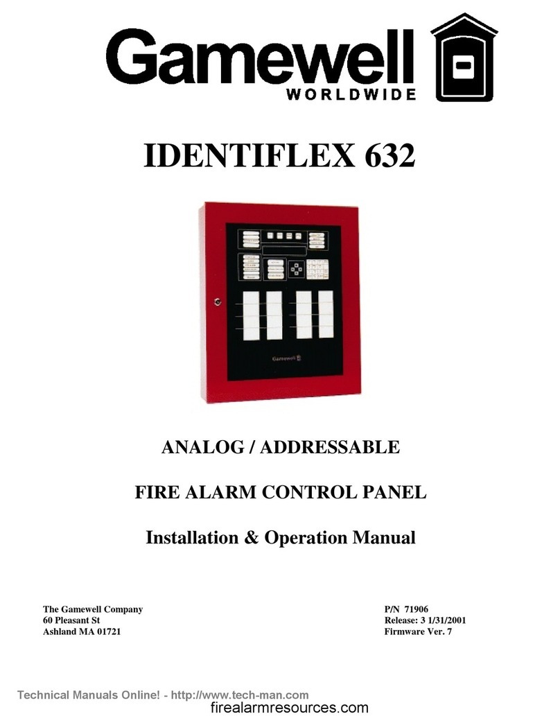
Gamewell Smart Start IDENTIFLEX 630 User manual

IDENTIFLEX 630
ANALOG / ADDRESSABLE
FIRE ALARM CONTROL PANEL
INSTALLATION & OPERATION MANUAL
P/N
71165
Revision - 3.0
Issued : 9-25-96


PROPRIETARY MATERIAL
The information contained in this manual is proprietary to The Gamewell Company.
Such information and technical drawings may not be copied or reproduced in any
manner, or disclosed to organizations that might be competitive to Gamewell, without
the express prior written consent of The Gamewell Company.


GENERAL INFORMATION
The Gamewell Company thanks you for choosing the IdentiFlex 630 to serve your monitor and control signaling needs.
As with all our products we have taken great care to insure that we have provided a quality Fire Alarm Control Panel. To
receive maximum benefit and many years of reliable service we would like to make the following recommendations:
1. Read this manual carefully and in it's entirety before proceeding with the installation of the IF630 control
panel.
2. Never make any connections with the power connected.
3. Gamewell spends many hours testing devices that are supplied by Gamewell to be used with it's control
panels to verify compatibility. To maximize system performance, and minimize risk of damage to the
equipment, we suggest using all Gamewell Components.
4. There is no substitute for proper maintenance and testing of this or any life safety product. Gamewell
recommends testing and maintenance of your IdentiFlex 630 system in accordance with the guidelines set
forth by the National Fire Protection Association, be done on a regular basis, as a minimum.
5. This manual should be stored with the IdentiFlex 630 for future reference, and should not be removed,
providing reference to the operation and programming of the installed IdentiFlex 630 System.
Thank you again for choosing Gamewell. If you have any comments regarding your IdentiFlex 630 Analog Addresable
Control Panel, or other Gamewell products, please feel free to write us at:
The Gamewell Company
Product Marketing Department
60 Pleasant Street
Ashland, MA 01721
Phone: (508) 231-1400
Fax: (508) 231-0900
E-Mail: GamewellCo@aol.com
WWW: http://www.gamewell.com


Table of Contents
SYSTEM DESCRIPTION.................................................................................................................................................. 1
SYSTEM OVERVIEW.........................................................................................................................................................2
IF 630 Control Panel...................................................................................................................................................2
SYSTEM MODULAR CONSTRUCTION.................................................................................................................................2
Common Control Section............................................................................................................................................2
System I/O Components..............................................................................................................................................3
SYSTEM OPERATION...................................................................................................................................................... 5
COMMON CONTROL DISPLAY-FUNCTIONAL DESCRIPTION................................................................................................6
Operator Display Controls..........................................................................................................................................6
Indicators ....................................................................................................................................................................7
SYSTEM OPERATING CONDITIONS ....................................................................................................................................8
Default Mode..............................................................................................................................................................8
Normal Quiescent Condition (default)........................................................................................................................8
Alarm Condition (default)...........................................................................................................................................9
OPERATING PROCEDURES...............................................................................................................................................10
Alarm Verification....................................................................................................................................................12
Supervisory Alarm Condition ...................................................................................................................................13
Trouble Condition.....................................................................................................................................................14
INSTALLATION.............................................................................................................................................................. 15
IdentiFlex 630 System Housing................................................................................................................................16
Hardware Assembly..................................................................................................................................................16
Module Identification and Placement .......................................................................................................................18
Main Power Supply...................................................................................................................................................19
Specifications............................................................................................................................................................19
Interconnects.............................................................................................................................................................19
Operators Display .....................................................................................................................................................19
CPU Module.............................................................................................................................................................20
Bus Driver Module ...................................................................................................................................................22
Common Control Specifications...............................................................................................................................24
ANALOG INTERFACE MODULE & SUBASSEMBLY SPECIFICATIONS.......................................................27
Analog Addressable Interface Module......................................................................................................................27
Analog Circuit Wiring Requirements and Limitations :............................................................................................28
Addressable Input Devices........................................................................................................................................29
FLEX 600 .................................................................................................................................................................30
COMPATIBLE INDICATING APPLIANCES........................................................................................................30
FLEX 600 .................................................................................................................................................................31
COMPATIBLE INDICATING APPLIANCES (Cont.) ...........................................................................................31
SYSTEM TEST MODE.................................................................................................................................................... 35
OVERVIEW......................................................................................................................................................................36
Detector Test.............................................................................................................................................................36
Walk Test..................................................................................................................................................................37
ByPass Mode ............................................................................................................................................................39

PROGRAMMING.............................................................................................................................................................42
PROGRAMMING FLOWCHART/OUTLINE ..........................................................................................................................43
INTRODUCTION...............................................................................................................................................................45
"SmartStart"...........................................................................................................................................................45
Programming Prompts..............................................................................................................................................45
SYSTEM STARTUP...........................................................................................................................................................47
Initial System Startup................................................................................................................................................47
SYSTEM RESTART / RE-CONFIGURATION - SMARTSTART...............................................................................................48
System Idle Display..................................................................................................................................................49
PASSWORD ENTRY - ACCESS LEVELS.............................................................................................................................49
Password Entry.........................................................................................................................................................50
PROGRAMMING MODE ...................................................................................................................................................51
Main Display ............................................................................................................................................................51
CIRCUIT PROGRAMMING...................................................................................................................................51
"Inputs" Circuit Selection.........................................................................................................................................51
Field Descriptions.....................................................................................................................................................52
Device Selection.......................................................................................................................................................52
Heat Device Operating Selection..............................................................................................................................53
Zone Type Selection.................................................................................................................................................53
Initiating Group Selection.........................................................................................................................................54
User Text Selection ..................................................................................................................................................54
Output Circuit Programming ....................................................................................................................................56
Field Descriptions for Signal Circuits and Analog Addressable...............................................................................58
Signal Circuit Types.................................................................................................................................................59
Output Signal Circuit Type.......................................................................................................................................59
Signal Circuit Restore...............................................................................................................................................59
Alarm Levels Available............................................................................................................................................60
Special Signal Circuit Functions...............................................................................................................................61
Restoring Outputs.....................................................................................................................................................61
Initializing an analog Circuit ....................................................................................................................................62
CONTROL BY EVENT......................................................................................................................................................63
CBE Programming....................................................................................................................................................63
To select "logical" Group Inputs ..............................................................................................................................63
To assign a "logical" Output Group..........................................................................................................................64
FUNCTION PROGRAMMING .............................................................................................................................................65
SYSTEM PROGRAMMING ................................................................................................................................................66
System Menu ............................................................................................................................................................66
Display Menu............................................................................................................................................................66
Config Menu............................................................................................................................................................66
Display Config..........................................................................................................................................................67
Download Config.....................................................................................................................................................70
Display Dict. Menu...................................................................................................................................................70
Display Dict..............................................................................................................................................................70
Download Dict..........................................................................................................................................................71
Display Events..........................................................................................................................................................71
Display, Misc............................................................................................................................................................71
Display Pass..............................................................................................................................................................72
Display Codes...........................................................................................................................................................73

Display Ver...............................................................................................................................................................74
Display RAM............................................................................................................................................................74
Change Menu............................................................................................................................................................75
Change Config ..........................................................................................................................................................75
Change Dictionary ....................................................................................................................................................75
Change Dict.Words...................................................................................................................................................75
Upload Dictionary.....................................................................................................................................................77
Dictionary File..........................................................................................................................................................77
Change Card..............................................................................................................................................................79
Change Misc .............................................................................................................................................................79
ChangeMenu 1..........................................................................................................................................................80
Change Pass..............................................................................................................................................................80
Change Code.............................................................................................................................................................81
Change Date..............................................................................................................................................................82
Change Seq ...............................................................................................................................................................82
Change Baud.............................................................................................................................................................83
Baud Rate Switch Settings........................................................................................................................................83
ChangeMenu 2..........................................................................................................................................................84
Change City...............................................................................................................................................................84
Change Sig Sil...........................................................................................................................................................84
Change Ann...............................................................................................................................................................84
Change Trbl ..............................................................................................................................................................85
Change Dialer ...........................................................................................................................................................85
Change Prefix............................................................................................................................................................85
Test Menu.................................................................................................................................................................86
Test Input..................................................................................................................................................................86
Test Output ...............................................................................................................................................................86
Test ID......................................................................................................................................................................86
Test Gnd....................................................................................................................................................................87
Test Lamps................................................................................................................................................................87
Test Analog...............................................................................................................................................................88
COMPUTER/LAPTOP PROGRAMMING OVERWIEW............................................................................................................90
Overview of Computer Programming......................................................................................................................90
Interconnect ..............................................................................................................................................................90
Communication Protocol ..........................................................................................................................................90
PROCOMM SOFTWARE....................................................................................................................................................90
Configuration............................................................................................................................................................90
Line Settings ............................................................................................................................................................90
Setup Menu...............................................................................................................................................................90
Terminal Setup.........................................................................................................................................................91
General Setup...........................................................................................................................................................91
ASCII Transfer.........................................................................................................................................................92
SYSTEM MONITORING & CONTROL................................................................................................................................92
Status Monitoring......................................................................................................................................................92
Access Levels............................................................................................................................................................92
Control Strings..........................................................................................................................................................92
APPENDIX....................................................................................................................................................................... 93
SYSTEM EVENT MESSAGES - Table O-1 ...........................................................................................................94

IF630 System Description 5/26/01
___________________________________________________________________________________________

Section 1
IDENTIFLEX 630
System Description

IdentiFlex 630 Installation and Operation Manual SmartStart Capable
9-25-96
2
SYSTEM OVERVIEW
IF 630
Control Panel The Gamewell IdentiFlex 630 (IF630) is a microprocessor based fire alarm control
panel. The IF630 system is available in three configurations; a 126 point, one circuit
analog/addressable circuit control panel (IF630-126), a 252 point, two circuit
analog/addressable circuit control panel (IF630-252), and a 504 point, four circuit
analog/addressable circuit control panel (IF630-504). The IF630-252 panel can be
expanded to 504 points by adding an expansion module (AAM-630E) ,a 252 point, 2
circuit, analog addressable expander card. The system is designed to accommodate a
wide variety of applications providing the user with a full range of features including;
self testing, self monitoring and full field programming capability. The IF630 system
comes complete with a system housing, a main 8 amp power supply, the analog
addressable module (1, 2, or 4 circuits) and the operators display module.
SYSTEM MODULAR CONSTRUCTION
Common Control
Section The common control section (CCS) consists of four modules; the operators display,
the bus driver module, a relay expansion module, and the main CPU module.
Operators
Display Module The operators display module (ODM) is the main user interface to the IF630 system.
It includes the interactive alphanumeric display, LED indicators, and tactile switches.
The operators display module provides the user with visual indications and guided
prompts during all operating conditions. All alarms, faults, or supervisory actions, as
well as system operating conditions (Normal, Alarms, Faults) are shown on the
alphanumeric display. LED’s provide indication and prompt the user to respond to the
next sequential action. The "Power On" LED indicator is green, alarms or activated
signal circuits and city tie are indicated by red LED's. Faults and user prompts are
indicated by yellow LED's.
Bus Driver
Module The bus driver module contains the circuitry that interfaces with the CPU and system
modules. The bus driver module is equipped with two Style Y or Z, limited energy
signaling circuits (2 amps maximum each) and a city tie circuit. It has three power
limited outputs for 24 Vdc auxiliary power, 12 Vdc, and resetable 24 Vdc smoke
detector power. Circuitry to monitor the status of the CPU and set the system in a
default mode of operation is also incorporated in the bus driver module.
Relay Expansion
Module The bus driver module is equipped with a relay expansion module. This module
provides Common Alarm, Common Trouble and Supervisory relays (Form c). Each
relay has a fused common rated at ten (10) amps. Each relay has a positive feedback
terminal for status indication. The expansion module mounts (via standoffs) to the
right side of the bus driver module. A spare relay is provided for future application.
CPU Module The CPU module (or microprocessor module) contains the system operating firmware
and non-volatile memory. It provides all the system memory and processing functions
as well as providing the local/remote communications and supervision.

IF630 System Description 5/26/01
___________________________________________________________________________________________
Rev 3.0 3
System I/O Components
Analog
Addressable
Module
The analog addressable module is a 1 or 2 circuit card that monitors and controls up
to 126 analog/addressable devices (points) per circuit for a total of 126 or 252 points
per module. The analog interface module has its own microprocessor which
simultaneously communicates with the connected field devices and with the main
CPU. Each analog/addressable circuit can be wired as a Style 4 (class B) or, Style 6
(class A) analog/addressable circuit.
Analog
Expansion
Module
For the IF630-252, the optional expansion module (AAM-630E) provides 2
additional analog addressable circuits allowing a total of 504 devices to be connected
to a system.
____________________________________________________________________________________________
Main Power
Supply The main power supply is an eight (8) amp DC supply. The main power supply has
provisions for a battery charger module and connections to the battery. Provisions
for "Brown Out" protection are functional when the main AC power drops below a
safe operating voltage level. Operating from a 120 VAC source, the main power
supply mounts in the lower left hand corner of the cabinet, and cables to the bus
driver module.
Lead Acid
Battery Charger
Module
The battery charger module is a plug-in type module and installs directly into the
main power supply card. This module will monitor and recharge 60 AH lead acid
type batteries and has provisions for extending the life of batteries. This is
accomplished by eliminating the build-up of contaminants on the plates.
____________________________________________________________________________________________
Addressable
Input Devices The IF630 system is designed to operate with Gamewell's complete line of analog
detectors (ionization, photoelectric) and with the IdentiFlex 600 series of
Addressable Input Devices. These input devices are available as either a single Point
Identification Device (PID-95) or as a manual pull station (MS-95). The addressable
input devices provide the means for communicating between the IF630 analog circuits
and contact devices or conventional type smoke detectors. Both the PID-95 and the
MS-95 devices are field programmable.


IF630 System Operation/Installation 5/26/01
___________________________________________________________________________________________
Rev 3.0 5
Section 2
IDENTIFLEX 630
System Operation

IdentiFlex 630 Installation and Operation Manual SmartStart Capable
9-25-96
6
COMMON CONTROL DISPLAY-FUNCTIONAL DESCRIPTION
Operator Display Controls
Refer to Figure 1 Common Control Display found at the end of section 2.
____________________________________________________________________________________________
Acknowledge
Switch The Acknowledge switch (ACK), silences the internal buzzer of the panel and
returns to normal. Any signal circuit or relay, programmed to return to normal
condition, when the "ACK" switch is depressed, will return to normal. Should a
second alarm activate the same points (signal circuit or relay programmed)
which have been returned to normal, the system will re-activate.
∆
∆∆
∆WARNING !
Do NOT reset the system until the Authority having
Jurisdiction has authorized reset.
Reset Switch The Reset switch (RESET) removes power from the initiating devices for a
period of four (4) seconds. Power is temporarily removed from the S+ S-
terminals. Any devices latched into alarm should return to the normal
condition, provided the cause of alarm has been eliminated. The signal circuits,
city tie, alarm relay and/or supervisory relay will restore, and the panel will
return to the normal quiescent condition.
Signal Silence The Signal Silence switch (SIGNAL SILENCE) will silence (i.e. return to
normal), any circuit or relay that is programmed to restore on Signal Silence.
The Signal Silence switch is an alternating action switch. Pressing the Signal
Silence switch will return the silenced circuits to an active state.
Drill The Drill switch (DRILL) will activate all circuits that have been programmed
to respond when the Drill switch is pressed. The Drill switch is alternate acting.
Pressing the Drill switch again will deactivate the test.
____________________________________________________________________________________________
Keypad Switches These switches are used for test and programming functions.
City Tie Used to test, program or bypass the city notification function, (see programming
sections).
Signal Circuit
1 & 2 Used to test, program or bypass signal circuits 1 or 2 (see programming
sections).
Arrow Keys Use to scroll the alphanumeric display and assist the user during system
programming.

IF630 System Operation/Installation 5/26/01
___________________________________________________________________________________________
Rev 3.0 7
Indicators
____________________________________________________________________________________________
POWER ON
Indication The green "Power On" LED indicates AC line operation. If pulsing, this
indicates a problem with the incoming AC line voltage.
ALARM The "Alarm" LED (red) indicates a common fire alarm has been activated in
the system.
PRE ALARM The PreAlarm LED (red) indicates that the system is in a first stage alarm
condition , such as alarm verification.
DRILL The Drill LED (yellow) indicates the Drill feature has been activated.
ACKNOWLEDGE The Acknowledge LED (yellow) will flash to indicate the next action is to
press the "ACK" switch.
SUPERVISORY
ALARM The Supervisory LED (yellow) indicates a supervisory zone has activated
(alarmed).
SIGNAL SILENCE The Signal Silence LED (red) will flash to indicate that the signal silence
switch is active.
CITY TIE The City Tie LED's are red for active, yellow for trouble.
SIGNAL CIRCUIT 1 Signal Circuit 1 LED's are red for active, yellow for trouble.
SIGNAL CIRCUIT 2 Signal Circuit 2 LED's are red for active, yellow for trouble.
RESET The Reset LED's (red) flash when the reset switch is available for use.
TROUBLE The Trouble LED (yellow) indicates the system is not in the normal
condition, a fault has been detected.
____________________________________________________________________________________________

IdentiFlex 630 Installation and Operation Manual SmartStart Capable
9-25-96
8
SYSTEM OPERATING CONDITIONS
Default Mode
WARNING NOTE
When shipped from the factory, the IdentiFlex 630 system has been initialized to
a minimal "default" configuration as part of our system testing procedures. It is
important that the system be re-initialized utilizing the SmartStart feature upon
installation. This will result in a customized default configuration.
The IF630 System will not recognize or communicate with any of the
connected devices until the SmartStart process has been exercised. The
IF630 will not report an alarm until this process has been completed. Refer
to the programming section of this manual for details about activating
SmartStart.
After the SmartStart routine has reinitialized the IF630, the system will be
configured as follows:
1. All (input) initiating points are configured to be "Automatic" initiating points
(standard smoke detector points). Point Identification Devices (PID's) shall be
configured as manual stations if the priority interrupt is set.
2. The system defaults to Security Level #2 (Acknowledge, Signal Silence and
Reset Switches are accessible without a password).
3. Whenever any input point(s) goes into alarm:
A. All output signaling circuits activate and produce a steady, 24VDC output.
B. All output relays are activated.
C. The city-tie and common alarm relays activated.
____________________________________________________________________________________________
Normal Quiescent
Condition (default) When the system is in the normal quiescent condition, the green "Power On" LED is
illuminated indicating the system is operating from normal AC line power. All
input and output circuits are "normal" (no alarm or trouble conditions). All other
LED's and alphanumeric display are extinguished, the system internal buzzer is
silent. To view system status message, press "Enter". Refer to Figure O-1.
In the normal condition, the green "Power-On" LED will be 'ON' - steady. All other
indicators will be extinguished.
ÛNOTE: The system is equipped with a built-in screen saver. When the system
remains in the idle mode (i.e. normal quiescent condition) for over 15 seconds the
screen will automatically go blank.
Status :Normal MM/DD/YY HH:MM
System Idle
Figure O-1

IF630 System Operation/Installation 5/26/01
___________________________________________________________________________________________
Rev 3.0 9
Alarm Condition
(default) The IdentiFlex 630 will go into an ALARM state when any analog/addressable
initiation device reports an alarm condition. By default the following actions will
occur at the common control display. Refer to Table O-1, System Events Messages
for complete listing of message displays.
1. The red "Alarm" LED will begin flashing. The flash rate is a continuously
repeating sequence of 1/4 second 'On' followed by 1/4 second 'Off'. The
internal system buzzer will sound.
2. The alphanumeric display will show the identification of the Alarm along with
date and time. (Refer to Figure O-2) Alarm information is logged into the
History Buffer to provide a time stamped record of the event's occurrence. In
the event of multiple alarms, the alphanumeric display can be scrolled (using
the up/down arrow keys) to show all active initiating devices.
3. The red Alarm LED for "City Tie" will light steady to indicate that the city tie
circuit has been activated.
4. Signaling Circuits indication will be as follows;
The red alarm LED's for (Signal Circuit 1 and Signal Circuit 2) will light
steady to indicate any signaling circuits that have been activated.
5. The Form C common alarm relay contacts will transfer.
6. The acknowledge switch red LED will begin to flash. This guided prompt
feature notifies the user that the next expected action is to press the "ACK"
switch - acknowledging the Alarm Condition.
Status : ALARM 1st of 1 MM/DD/YY HH:MM
Fire Alarm in Ckt#_ Dev#:_
Figure O-2
Display for Multiple Alarm(s)
•NOTE: Multiple alarms are shown after the words ALARM Total
“x”; with “x” representing the total amount of alarms.
Status : ALARM Total X MM/DD/YY HH:MM
Fire Alarm in Ckt#_ Dev#:_
Figure O-3

IdentiFlex 630 Installation and Operation Manual SmartStart Capable
9-25-96
10
OPERATING PROCEDURES
Acknowledging
the Alarm
Condition
When the user presses the "ACK" switch to acknowledge an alarm condition,
the following actions will occur.
1. The control panel's internal audible buzzer will (always) silence.
2. The acknowledge key's activation is logged into the History Buffer to
provide a time stamped record of the event's occurrence.
3. The Acknowledge red LED will extinguish.
4. Any outputs programmed to return to the normal condition upon pressing
the "ACK" switch will return to normal at this time.
5. The red LED's for RESET and SIGNAL SILENCE switches will flash.
This "guided prompt" feature notifies the user that the next expected action
is to Reset the system or Silence the signals (if so programmed).
____________________________________________________________________________________________
Signal Silence In the Alarm condition, the red LED for SIGNAL SILENCE will begin to flash.
This guided prompt feature notifies the user that it is possible, but not
necessary, to press the SIGNAL SILENCE switch. In the default mode, all
signal circuits will silence.
If the user presses the SIGNAL SILENCE switch, the following actions will
occur:
1. The LED for the SIGNAL SILENCE switch will remain flashing.
2. All output signal circuits which have been programmed to silence when the
SIGNAL SILENCE switch is activated (which is all output circuits in the
"default" case) will silence and the red activated LED will extinguish.
Resound or Return
of Signals 1. The signal silence switch is an alternating action switch. If the user
subsequently presses the SIGNAL SILENCE switch again, the signal
circuits will activate.
2. All the output signal circuits which had deactivated will reactivate;
returning to the Alarm condition. Tthe red active LED’s will light.
____________________________________________________________________________________________
This manual suits for next models
2
Table of contents
Other Gamewell Fire Alarm manuals
Popular Fire Alarm manuals by other brands

Panasonic
Panasonic EBL512 G3 5000 operating instructions

Zeta
Zeta ID2/8 quick start guide

Global Fire Equipment
Global Fire Equipment JUNIOR V3 Operation & maintenance manual

Ampac
Ampac MAN 3038 Product guide

Mircom
Mircom FleXNet FNC-2000 Installation and operation manual

Simplex
Simplex 4098-5217 installation instructions