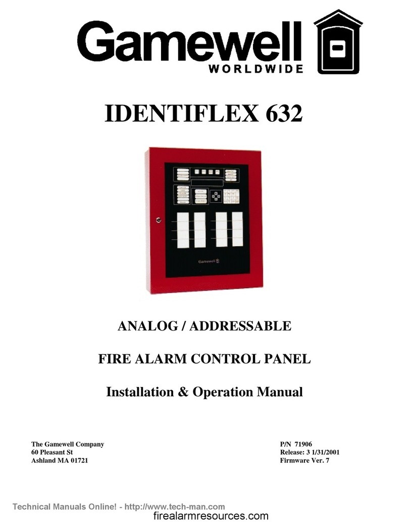
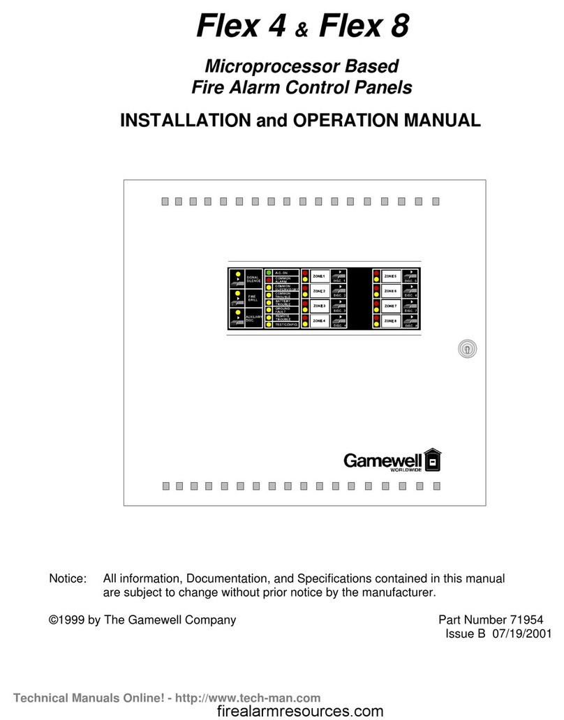
Gamewell FLEXALARM 620 User manual

FLEXALARM 620
CONVENTIONAL
FIRE ALARM CONTROL PANEL
Installation & Operation Manual
The Gamewell Company P/N 71217
60 Pleasant Street Revision 5
Ashland, MA 01721 11-22-01
UL, FM, CSFM, MEA Listed
Technical Manuals Online! - http://www.tech-man.com

This page intentionally blank
Technical Manuals Online! - http://www.tech-man.com

PROPRIETARY MATERIAL
The information contained in this manual is proprietary to The Gamewell Company. Such information
and technical drawings may not be copied or reproduced in any manner, or disclosed to organizations
that might be competitive to Gamewell, without the express prior written consent of The Gamewell
Company.
Technical Manuals Online! - http://www.tech-man.com

This page intentionally blank
Technical Manuals Online! - http://www.tech-man.com

GENERAL INFORMATION
The Gamewell Company thanks you for choosing the FLEXALARM 620 Conventional Control Panel to
serve your monitor and control signaling needs. As with all our products we have taken great care to insure
that we have provided a quality alarm control panel. To receive maximum benefit and many years of
reliable service we would like to make the following recommendations:
1. Read this manual carefully and in it's entirety before proceeding with the installation of the Flex 620
Control Panel.
2. Never make any connections or perform any system programming with the power connected.
3. Gamewell spends many hours testing devices that are supplied by Gamewell to be used with it's control
panels to verify compatibility. To maximize system performance, and minimize risk of damage to the
equipment, we suggest using all Gamewell Components.
4. There is no substitute for proper maintenance and testing of this or any Life Safety product. Gamewell
recommends testing and maintenance of your FLEX 620 system in accordance with the guidelines set
forth by the National Fire Protection Association, be done on a regular basis, as a minimum.
5. This manual should be stored with the FLEX 620 Control Panel for future reference, and should not be
removed.
Thank you again for choosing Gamewell. If you have any comments regarding your FLEX 620 Conventional
Control Panel, or other Gamewell products, please feel free to write us at:
The Gamewell Company
Product Marketing Department
60 Pleasant Street
Ashland, MA 01721
Phone: (508) 231-1400
Fax: (508) 231-0900
Technical Manuals Online! - http://www.tech-man.com

This page intentionally blank
Technical Manuals Online! - http://www.tech-man.com

Technical Manuals Online! - http://www.tech-man.com

This page intentionally blank
Technical Manuals Online! - http://www.tech-man.com

TABLE OF CONTENTS
SYSTEM OVERVIEW ..................................................................................................................................................... 2
FLEX 620 Control Panel..................................................................................................................................... 3
Modular Construction.......................................................................................................................................... 3
Common Control Module.................................................................................................................................... 4
SYSTEM I/O COMPONENTS (600 SERIES).................................................................................................................... 6
Initiating Module................................................................................................................................................. 6
Indicating Module................................................................................................................................................ 6
600 Series Modules ............................................................................................................................................. 7
SYSTEM OPERATION............................................................................................................................................... 9
COMMON CONTROL DISPLAY - FUNCTIONAL DESCRIPTION................................................................................... 10
CONTROLS...................................................................................................................................................... 10
INDICATORS................................................................................................................................................... 11
Standard Operating Display - (Legend Key Designators).................................................................................. 12
Module Displays................................................................................................................................................ 13
SYSTEM OPERATING CHARACTERISTICS.................................................................................................................. 14
Overview ........................................................................................................................................................... 14
Alarm Verification............................................................................................................................................. 15
And Initiating Circuit......................................................................................................................................... 16
SYSTEM OPERATING CONDITIONS ............................................................................................................................ 17
Default Mode..................................................................................................................................................... 17
Normal Quiescent Condition ............................................................................................................................. 17
(default) ............................................................................................................................................................. 17
Alarm Condition (default) ................................................................................................................................. 18
OPERATING PROCEDURES ......................................................................................................................................... 19
INSTALLATION........................................................................................................................................................ 24
Flex 620 System Housing.................................................................................................................................. 25
Hardware Assembly........................................................................................................................................... 26
Module Identification and Placement................................................................................................................ 28
Main Power Supply ........................................................................................................................................... 30
Specifications..................................................................................................................................................... 30
Interconnects...................................................................................................................................................... 30
Auxiliary Power Supply..................................................................................................................................... 31
Interconnects...................................................................................................................................................... 31
Common Control Specifications........................................................................................................................ 32
Bus Driver Module............................................................................................................................................ 35
CPU Module...................................................................................................................................................... 36
SYSTEM I/O COMPONENTS (600 SERIES).................................................................................................................. 38
Conventional Input Module.............................................................................................................................. 38
Conventional Input Module Terminal Description............................................................................................ 39
Class "A" Adapter -Conventional Input Module - Terminal Description.......................................................... 39
Universal Signal Circuit Module....................................................................................................................... 40
Universal Signal Circuit Module Terminal Description.................................................................................... 41
Class "A" Adapter - Universal Signal Module - Terminal Description............................................................. 41
Technical Manuals Online! - http://www.tech-man.com

Relay Module .................................................................................................................................................... 42
Relay Module ................................................................................................................................................... 43
Relay Expansion Module................................................................................................................................... 43
Building Control Module................................................................................................................................... 44
Building Control Module................................................................................................................................... 45
City Tie Extender Module................................................................................................................................. 46
Initial System Startup......................................................................................................................................... 47
FLEX 600 CONTROL PANEL......................................................................................................................... 48
COMPATIBLE SMOKE DETECTORS & BASES ......................................................................................... 48
FLEX 600 CONTROL PANEL......................................................................................................................... 48
COMPATIBLE AUXILIARY DEVICES......................................................................................................... 48
FLEX 600 CONTROL PANEL......................................................................................................................... 48
COMPATIBLE INITIATING DEVICES FOR “AND“ ZONES...................................................................... 48
FLEX 600.......................................................................................................................................................... 49
COMPATIBLE INDICATING APPLIANCES ................................................................................................ 49
FLEX 600.......................................................................................................................................................... 50
COMPATIBLE INDICATING APPLIANCES (Cont.).................................................................................... 50
PROGRAMMING...................................................................................................................................................... 53
PROGRAMMING OVERVIEW - FLEXALARM 620 ...................................................................................................... 54
Programming Options........................................................................................................................................ 55
Control By Event............................................................................................................................................... 59
Access Levels .................................................................................................................................................... 60
Figure 4.1 Common Control Display - Operating Mode ................................................................................. 60
Password Entry.................................................................................................................................................. 60
Input Circuit - Programming.............................................................................................................................. 63
Output Circuit - Programming........................................................................................................................... 64
Restoring Output Circuits.................................................................................................................................. 65
Programming Signal Circuit Special Functions................................................................................................. 66
Control-By-Event - Programming...................................................................................................................... 67
COMPUTER/LAPTOP PROGRAMMING OVERVIEW .................................................................................................... 68
Overviewof Computer Programming................................................................................................................. 68
Interconnect....................................................................................................................................................... 68
Communication Protocol................................................................................................................................... 68
PROCOMM SOFTWARE............................................................................................................................................... 68
Configuration..................................................................................................................................................... 68
Line Settings..................................................................................................................................................... 68
Setup Menu........................................................................................................................................................ 68
Terminal Setup ................................................................................................................................................. 69
General Setup ................................................................................................................................................... 69
ASCII Transfer................................................................................................................................................. 70
SYSTEM MONITORING & CONTROL.......................................................................................................................... 70
Status Monitoring .............................................................................................................................................. 70
Access Levels .................................................................................................................................................... 70
Control Strings................................................................................................................................................... 70
SYSTEM PROGRAMMING VIA COMPUTER ................................................................................................................. 71
System Menu..................................................................................................................................................... 71
Display Menu .................................................................................................................................................... 71
Config Menu..................................................................................................................................................... 71
Display Config................................................................................................................................................... 72
Technical Manuals Online! - http://www.tech-man.com

System Configuration ........................................................................................................................................ 73
Codes Defined ................................................................................................................................................... 73
Modular Placement............................................................................................................................................ 73
Card Locations................................................................................................................................................... 73
0 through 7......................................................................................................................................................... 73
Cards # 8 - 39 .................................................................................................................................................... 73
Module Bus ....................................................................................................................................................... 73
Card ID #........................................................................................................................................................... 73
Download Config.............................................................................................................................................. 75
Display Dict. Menu............................................................................................................................................ 75
Display Dict....................................................................................................................................................... 76
Download Dict................................................................................................................................................... 76
Display Events................................................................................................................................................... 77
Display, Misc..................................................................................................................................................... 77
Display Pass....................................................................................................................................................... 78
Display Codes.................................................................................................................................................... 79
Display Ver........................................................................................................................................................ 80
Display Zone...................................................................................................................................................... 80
Change Menu..................................................................................................................................................... 81
Change Config................................................................................................................................................... 81
Change Dictionary............................................................................................................................................. 81
Change Dict.Words ........................................................................................................................................... 82
Upload Dictionary ............................................................................................................................................. 82
Dictionary File................................................................................................................................................... 83
Change Card...................................................................................................................................................... 84
Change Misc...................................................................................................................................................... 84
Change Menu 1.................................................................................................................................................. 85
Change Pass....................................................................................................................................................... 85
Change Code...................................................................................................................................................... 86
Change Date ...................................................................................................................................................... 87
Change Seq........................................................................................................................................................ 87
Change Baud...................................................................................................................................................... 88
Baud Rate Switch Settings................................................................................................................................. 88
Change Words ................................................................................................................................................... 89
Change Menu 2.................................................................................................................................................. 91
Change City....................................................................................................................................................... 91
Change Sig Sil ................................................................................................................................................... 91
Change Ann....................................................................................................................................................... 91
Change Trbl....................................................................................................................................................... 92
Change Dialer.................................................................................................................................................... 92
Change Prefix.................................................................................................................................................... 92
Test Menu.......................................................................................................................................................... 93
Test Input........................................................................................................................................................... 93
Test Output........................................................................................................................................................ 94
Test ID............................................................................................................................................................... 94
Test Gnd ............................................................................................................................................................ 95
Test Lamp.......................................................................................................................................................... 95
IDENTIFLEX 620 BATTERY CALCULATION CHART ............................................................................. 96
Technical Manuals Online! - http://www.tech-man.com

Technical Manuals Online! - http://www.tech-man.com

This page intentionally blank
Technical Manuals Online! - http://www.tech-man.com

Flex 620 System Description - Revision 5, 11/22/01
2
Section 1
FLEXALARM 620
System Description
System Overview
Technical Manuals Online! - http://www.tech-man.com

Flex 620 System Description - Revision 5, 11/22/01
3
FLEX 620
Control Panel The Gamewell FlexAlarm 620 Conventional Alarm Control Panel is a limited energy
fire, supervisory, alarm system consisting of a cabinet, I/O circuits, power supplies,
and front panel displays. The Flex 620 is expandable to monitor, control and display
up to 128 input/output circuits. It is available in two cabinet sizes, four bay and eight
bay. The four bay cabinet (F624) will accommodate 4 of the 620 series modules in
addition to the common control, power supply and batteries. The eight bay cabinet
(F628) will accommodate 8 of the 620 series modules in addition to the common
control, power supply and batteries.
The design of the system utilizes a modular building block approach. Through
selection of individual I/O modules (i.e. initiating, indicating and relay control
modules, etc.) the user can customize the control panel for specific applications.
The Flex 620 control panel utilizes a unique initialization programming process,
SmartStart. This initialization process stores the project specific system
configuration in memory. Then a control-by-event table is automatically created that
allows any system input to activate the system outputs. Upon completion of the
initialization process the system is completely operable in a general alarm situation
with the control-by-event data tables protected in non-volatile memory.
___________________________________________________________________________________________
Modular
Construction The Flex 620 modular control panel consists of the common control section,
conventional input module(s), universal signal module(s), relay module(s), building
control module(s), city tie module(s), and power supplies. Other devices that can be
used in conjunction with the Flex 620 system include the remote annunciators, printer
interfaces and alphanumeric displays. These devices operate by means of the serial
communications port which is isolated via an optional communications isolator
module.
The cabinet utilizes dead front construction in either a four or eight bay arrangement.
The modules will conform to numerous system configurations that accommodate
simple and complex systems.
____________________________________________________________________________________________
Technical Manuals Online! - http://www.tech-man.com

Flex 620 System Description - Revision 5, 11/22/01
4
Common
Control Module The common control module (CCM) or section consists of four modules; the common
control display, the bus driver module, a relay expansion module, and the main CPU
module.
Common
Control
Display
The Common Control Display (CCD) is divided into two sections, the left and right
displays. It provides the user with visual indicators (LED's) for status indication and
guided prompts. The sixteen tactile switches are used to operate the system as well as
enter data during system programming. All alarm, fault, supervisory and security
status changes are annunciated by means of LED indication and the user is prompted
with the proper sequence of operation. The "Power On" LED indicator is green,
alarms or activated signal and city tie circuits are indicated by red LED's and faults are
indicated by yellow LED's.
CPU Module The CPU module (or micro processor module) contains the system operating firmware
and non-volatile memory. It provides all the processing functions and system memory
as well as providing the local/remote communications interface.
Relay
Expansion
Module
The Relay Expansion Module (REM) provides 4 common relay circuits. When
connected to the bus driver module this module provides Common Alarm, Common
Trouble and Supervisory Form C relay contacts. Each relay has a fused common rated
at ten (10) amps. The expansion module mounts (via standoffs) to the right side of the
bus driver module.
Bus Driver
Module The Bus Driver Module (BDM) contains the circuitry that interfaces with the CPU
module and the system modules. The bus driver module is equipped with two Style Y
or Z, limited energy signaling circuits, a ground fault detection circuit and a city tie
circuit. It has three power limited outputs, 24 Vdc auxiliary power, 12 Vdc, and
resetable 24 Vdc smoke detector power. Circuitry to monitor the status of the CPU
and set the system in a default mode of operation is also incorporated in the bus driver
module.
___________________________________________________________________________________________
620 Common Control Module
Bus Driver
Module
Common Control
Display
Relay Expansion
Module
CPU Module
Technical Manuals Online! - http://www.tech-man.com

Flex 620 System Description - Revision 5, 11/22/01
5
Main
Power Supply
The main power supply (MPS-8) is an eight (8) amp DC supply. It provides 4 amps
of regulated 5, 12, and 24 volt DC outputs and four amps of unregulated 24 volt DC
power to the common control signal circuits. A battery charger and battery
distribution block are incorporated into the Main Power Supply. A "Brown Out"
protection circuit that will switch the main and any auxiliary power supplies to
battery standby is also integrated into the supply. The main power supply mounts in
the lower left hand corner of the cabinet and connects via interconnecting cables to
the bus driver module.
Lead Acid
Battery
Charger
The lead acid battery charger module is provided with the main power supply. The
battery charger module is capable of charging and maintaining up to 60 AH batteries.
Auxiliary
Power Supply
The auxiliary power supply (APS-8) provides eight (8) amps of unregulated 24 VDC
power. Two (2), four (4) amp circuits are available from its connectors for signaling
power expansion. The auxiliary power supply has provisions for receiving a signal
from the main supply to switch to battery standby due to low (Brown out) or no
primary input.
Main Power Supply (Left)Auxiliary Power Supply (Right)
Technical Manuals Online! - http://www.tech-man.com

Flex 620 System Description - Revision 5, 11/22/01
6
System I/O Components (600 Series)
___________________________________________________________________________________________
Initiating Module
Conventional
Input Module The 600 series Conventional Input Modules (CIM-4 & CIM-8) are available in either
4 or 8 initiating circuits for monitoring of conventional detectors and contact type
devices. Its corresponding display provides status indication and Bypass/
programming capabilities. Each zone can be programmed to meet the requirements of
NFPA Styles B (Class B). An optional Class A adapter may be used to meet the
requirements of NFPA Style D if required.
CIM Display The display module provides LED annunciation of Alarm and Trouble conditions and
has one switch per zone for programming and bypass functions. The display has
provisions for user defined custom labels per circuit. LED annunciation is indicated
by - red - Alarm (active) and - yellow - Trouble.
___________________________________________________________________________________________
Indicating Module
Universal
Signal Module The Flex 600 series universal signal modules (USM-4 & USM-8) are a multi-function
output modules available in either 4 or 8 circuit increments. These modules can be
programmed to function as either notification appliance circuits, releasing circuits,
speaker circuits or fireman's telephone circuits. When used as notification appliance
circuits, these modules can be programmed for steady, 60PPM, 120PPM, temporal,
zone coded or California UFC signaling outputs. These circuits are designed to meet
the requirements of NFPA 72, Style Y notification appliance circuits. An optional
Class A adapter is available to meet the requirements of NFPA 72, Style Z
notification appliance circuits.
USM Display The display module provides LED annunciation of Alarm and Trouble conditions and
has one switch per zone for programming and bypass functions. The display has
provisions for user defined custom labels per circuit. The module displays are
supplied with user tactile switches per circuit. LED annunciation indication is - red -
Alarm (active) and - yellow - Trouble.
___________________________________________________________________________________________
Technical Manuals Online! - http://www.tech-man.com

Flex 620 System Description - Revision 5, 11/22/01
7
600 Series Modules
Relay Modules The 600 series relay modules (RM-4 and RM-8) have been designed to supply 4 or 8
Form C relays for control of auxiliary functions. The relays are controlled by the
main CPU and are fully field programmable. A feedback point for positive
confirmation of activation has been supplied with each set of contacts. The relays are
rated at 10 amps with a fused common to protect the internal circuitry.
Relay Display The relay module display is provided with green (inactive) and red (active) LED's.
The tactile switches (per relay point) can be used to program, bypass or test the relay
circuits.
___________________________________________________________________________________________
Building
Control
Module
The 600 series building control modules, (BC-4 & BC-8) along with their
On/Off/Auto switch display, are designed to provide an interface between the control
panel and HVAC systems. The building control module is available in 4 or 8 circuit
modules that are monitored and controlled by the MPU bus. Their relays are rated at
10 Amps with supervised feedback points for positive confirmation of the
programmed action. Each Form A/B relay pair is programmable independently and
fused on the relay common to protect the internal circuitry.
BCM Display The building control module display provides LED annunciation (green - inactive,
and red - active) indicating relay state or feedback. The display comes with tactile
switches per circuit and a three position On/Off/Auto switch for manual override.
___________________________________________________________________________________________
City Tie
Module The 600 series City Tie Module and its associated display provide 4 additional,
limited energy, polarity reversal/city tie circuits to a system. Each circuit has
independently programmable operation.
Module
Displays The city tie module displays are supplied with red Alarm (active) and yellow Trouble
LED's with user tactile switches for programming, bypass and test per circuit.
Representative Inner Cabinet Module Assembly (USM, CIM, RM)
Technical Manuals Online! - http://www.tech-man.com

Technical Manuals Online! - http://www.tech-man.com
Table of contents
Other Gamewell Fire Alarm manuals
Popular Fire Alarm manuals by other brands

Simplex
Simplex LifeAlarm 4005 Series Programming instructions

Notifier
Notifier AFC-600 operating manual

UTC Fire and Security
UTC Fire and Security Aritech DM2010 Installation sheet

Shield
Shield D-A412 user manual

Teletek electronics
Teletek electronics SensoIRIS T110 IS quick guide

SILENT KNIGHT
SILENT KNIGHT INTELLIKNIGHT 5820XL Installation and operation manual