Gammon Aqua-Glo III Series User manual

APPENDIX E
WATER DETECTION (AQUA-GLO) TEST
EQUIPMENT
To test aviation fuels for undissolved (free) water, use the Aqua-Glo III
ultraviolet detector kit as shown in (Figures E-1A and E-1B). The standard
test method for undissolved water is ASTM D 3240-86a. The following
equipment is required to perform this test:
Aqua-Glow series III Free Water Detector Unit
The Aqua-Glo series III determines the degree of undissolved water content.
The ultraviolet lamp assembly has a single, permanent fluorescing standard,
p
ositioned under a photographic-type iris diaphragm that can be opened or
closed to increase or decrease the amount of ultraviolet light. The water
content is determined by adjusting the diaphragm lever arm until the
fluorescing standard and the test pad shows equal brightness in the ultraviolet
light. The balance is reached when the zero-centering ammeter reads ZERO.
The amount of water is read in parts per million (PPM) on the diaphragm
lever arm scale that has been precalibrated in the factory.
Test Pads
The fuel sample passes through a uranine dye-treated filter pad. Free water in
the fuel reacts with the uranine dye. When the pad is illuminated by ultraviolet
light, the dye contacted by the free water will fluoresce a bright yellow. The
p
ad is packaged in a hermetically sealed packet. The test pads are packaged 50
to a box.
Test Pad Holder and Sample Line
A test pad holder and sample line are used to draw the fuel sample through the
Amprobe Products
Amprobe Electrical meters Amprobe and TIF
a Division of ATP
Resistance Meter
0.1u-ohm to 110M-ohm High Accuracy &
High Speed
Ads by Goooooogle
Pa
g
e 1 of 10FM 10-67-1 APPENDIX E
5/30/2005htt
p
://www.
g
lobalsecurit
y
.or
g
/militar
y
/librar
y
/
p
olic
y
/arm
y
/fm/10-67-1/APPE.HTML

test pad. The test pad holder is coupled to a sampling coupler mounted on the
downstream side of the filter/separator.
Paper towels or blotters
Paper towels or blotters are used to remove excess fuel from the test pad
before testing is conducted for prior to testing for free water.
Tweezers
Tweezers are used at all times when handling the test pad is being handled.
Figure E-1A. Aqua-Glo Series III ultraviolet detector kit
Figure E-1B. Aqua-Glo Series III ultraviolet detector kit
Pa
g
e 2 of 10FM 10-67-1 APPENDIX E
5/30/2005htt
p
://www.
g
lobalsecurit
y
.or
g
/militar
y
/librar
y
/
p
olic
y
/arm
y
/fm/10-67-1/APPE.HTML

TEST PREPARATION
To ensure accurate free water detection, the Aqua-Glo III detector must be
assembled for operation and calibrated before each use and after every hour of
use. These procedures are described below:
zSlide the meter assembly into the track on the ultra violet lamp assembly.
zTurn on the water detector, setting the indicator switch to the appropriate
power source: set to AC (50 or 60 Hz, 110-120v, using power cord),
internal battery, or external battery (using external battery cord). See
Figure E-2. When using the internal battery, ensure the battery is charged
if the battery is in a low or no battery power condition. A low battery
condition can be identified by sluggish response of the meter or failure of
the detector to stay calibrated during two successive tests. Use of the
detector in a low or no battery condition will provide inaccurate test
results.
zRemove the calibration pad stored in the kit. Always handle the pad with
tweezers The pad is covered with a clear plastic shielding and has a
coding standard written on one side. Note the "SET" code in the center of
the pad, this is the calibration setting you will use for calibrating. The
sample pad in Figure E-3 has a calibration set code of "5.3.---" Ensure
that the calibration and fluorescing standard are a matched set. The
fluorescing standard located under the hinged light shield has an
alphanumeric code, and should match the code on the calibration
standard. Although the "SET" numbers on the standards may or may not
be the same, the code for the standards must be the same. You should
label or mark the detector with the calibration/fluorescing code to ensure
the proper pad is used during calibration. Matched standard sets can be
ordered under NSN 6630-01-245-5989.
zUsing tweezers, insert the calibration pad in the test area window located
on the bottom of the water detector. Lift the covers curved metal tab and
place the pad (text facing you) in the depressed circular area in the center
of the test area as shown in Figure E-4. Close the test area cover and
stand the water detector upright.
zPosition the light-modulator lever, located on the side of the water
detector, until the lever is directly above the number on the scale
corresponding to the set number shown on the calibration pad as shown
in Figure E-5.
Pa
g
e 3 of 10FM 10-67-1 APPENDIX E
5/30/2005htt
p
://www.
g
lobalsecurit
y
.or
g
/militar
y
/librar
y
/
p
olic
y
/arm
y
/fm/10-67-1/APPE.HTML

zDepress the switch button on the instrument pack and read the calibration
meter. If the meter reads "0," the water detector is calibrated as shown in
Figure E-6. If the meter reads any increment other than "0," you must
adjust the internal calibration screw until the water detector is "zeroed-
out."
zTo adjust the internal calibration screw, remove the outer screw on the
side of the calibration meter housing using the jeweler’s screwdriver.
Insert the jeweler’s screwdriver into the housing and turn the internal
adjustment screw. Depress the switch button on the instrument pack as
you turn the screw until the meter lever reads "0." Replace the outer
screw and the water detector is calibrated. See Figure E-7.
zRemove the calibration pad from the test area, using tweezers, and place
it back in the kit.
Figure E-2. AC/internal/external power settings
Pa
g
e 4 of 10FM 10-67-1 APPENDIX E
5/30/2005htt
p
://www.
g
lobalsecurit
y
.or
g
/militar
y
/librar
y
/
p
olic
y
/arm
y
/fm/10-67-1/APPE.HTML

Figure E-3. Calibration pad and calibration set code
Figure E-4. Placement of calibration pad in test area window
Pa
g
e 5 of 10FM 10-67-1 APPENDIX E
5/30/2005htt
p
://www.
g
lobalsecurit
y
.or
g
/militar
y
/librar
y
/
p
olic
y
/arm
y
/fm/10-67-1/APPE.HTML

Figure E-5. Set the light-modulator lever
Figure E-6. Calibration meter lever shaft reading "0"
Pa
g
e 6 of 10FM 10-67-1 APPENDIX E
5/30/2005htt
p
://www.
g
lobalsecurit
y
.or
g
/militar
y
/librar
y
/
p
olic
y
/arm
y
/fm/10-67-1/APPE.HTML

Figure E-7. Zeroing-out the meter lever
SAMPLING PROCEDURES
The sampling coupler must be permanently attached to a fuel probe mounted
downstream from the filter/separator. For the test to be accurate, the sample
must be taken from a moving stream of fuel. The sample should be drawn at a
rate of 600 to 800 mL/minute. When sampling the fuel in a system, ensure the
p
ump is running and at least one nozzle is open. If sampling the fuel in a filter,
take the sample while recirculating the fuel before operations. Take the
sample using the procedures described below.
zCouple the detector pad holder assembly, with the toggle valve closed
(parallel to the line), to the sampling coupler. The detector pad holder
assembly includes plastic tubing, the detector pad holder, toggle valve,
and sampling coupler.
zFlush the sampling line immediately before sampling. Put the end of the
plastic tubing in a container that will hold approximately 1 gallon. (Note:
The amount of free water in a sample is very sensitive to the temperature
of a sample. Using bottles or cans for a sample container could result in
errors due to sample temperature or adsorption of water on container
walls.) Open the toggle valve by turning the handle up (perpendicular to
the line). Flush the detector pad assembly by displacing at least 1 liter of
Pa
g
e 7 of 10FM 10-67-1 APPENDIX E
5/30/2005htt
p
://www.
g
lobalsecurit
y
.or
g
/militar
y
/librar
y
/
p
olic
y
/arm
y
/fm/10-67-1/APPE.HTML

product.Shut the toggle valve and uncouple the detector pad assembly.
zUnscrew the two halves of the detector pad holder. Using tweezers, take
the detector pad out of its envelope and put it, orange side up, in the
recess in the outlet side of the holder. If the sample pad has any
discoloration, unevenness in dye content, or a faded yellow appearance,
select another sample pad. Screw the pad holder assembly back together.
When using a three-way valve, the assembly may be flushed with the pad
in place. Do not remove the test pad from the hermetically sealed
envelope until ready for use. The pad can absorb moisture from the air,
rain, or sneezing. Exposing the test pad to the air on a humid day will
ruin the pad in a matter of minutes.
zCouple the detector pad assembly back to the sampling coupler, with the
toggle valve closed, and put the end of the plastic tubing into the neck of
the plastic sample bottle. Open the toggle valve and allow 500 mL of
product to pass through the sample pad. Normal sample volume is 500
mL, but if the reading is off scale, sample volumes as low as 100 mL may
be used.
zClose the toggle valve and uncouple the detector pad holder from the
sampling coupler. Unscrew the detector pad holder. Slip one prong into
the notch in the pad holder, and lift the pad out. Press the test pad
between dry paper towels or blotters to remove excess fuel.
TEST PROCEDURES
Test the fuel after the equipment has been prepared and the sample is drawn.
For maximum accuracy, read the test pad within three minutes after sampling
is begun.Use the following procedures for testing.
zUsing tweezers, put the pad in the test pad slot in the bottom of the
ultraviolet lamp assembly. Ensure that the orange side faces the
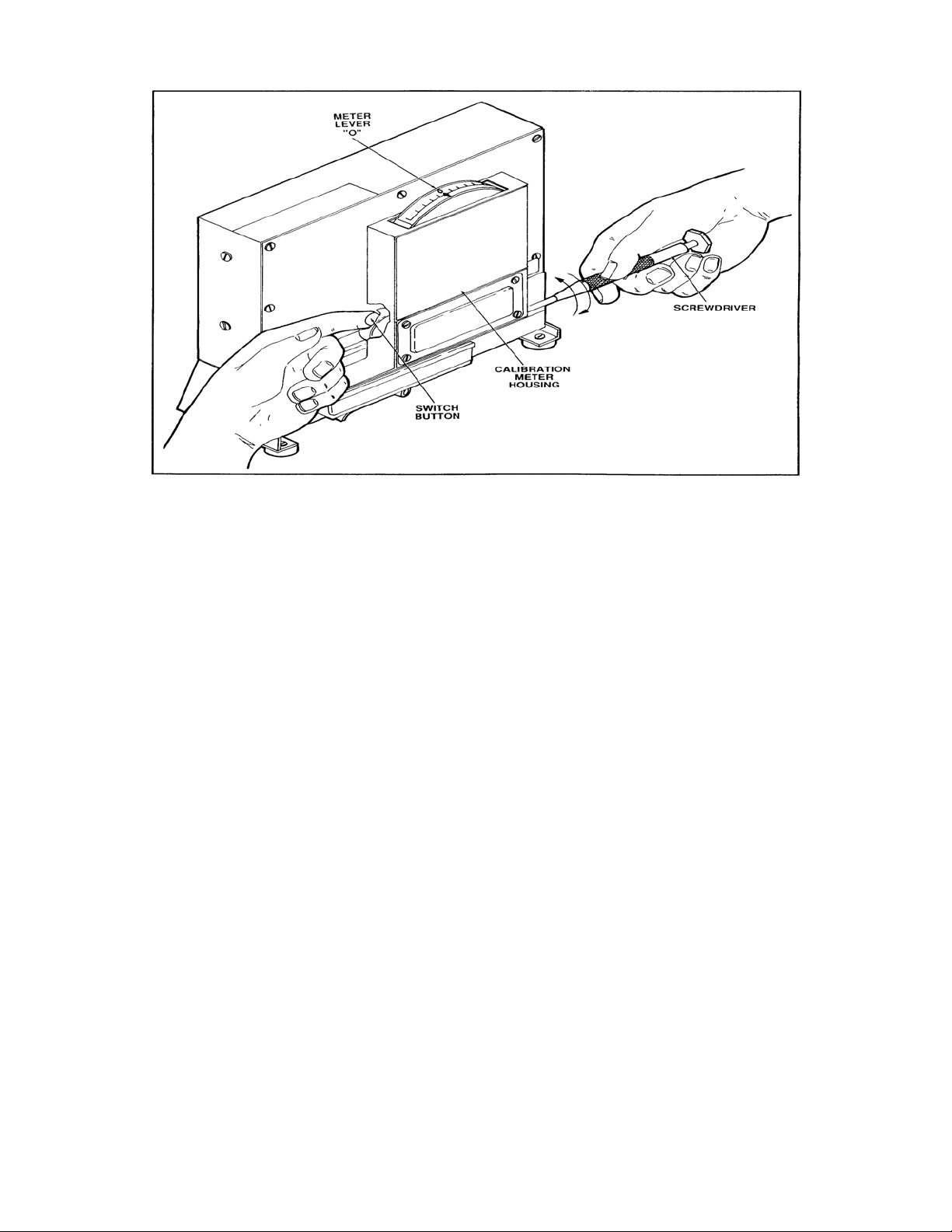
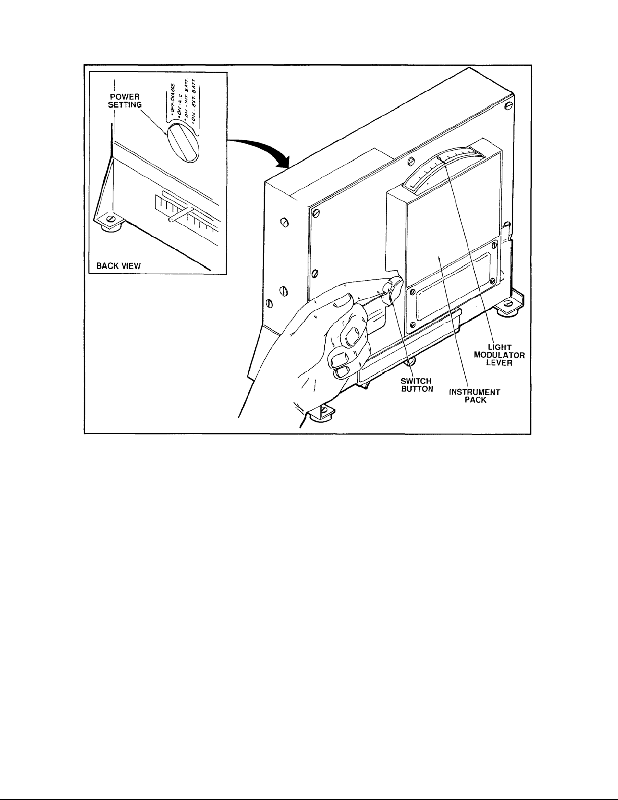
ultraviolet lamp. Turn on the lamp. Press the hooded button of the meter
assembly while moving the light modulator lever as shown in Figure E-8.
Watch the meter scale while moving the light modulator lever until the
meter pointer points to zero. Always move the modulator arm in the same
direction to avoid backlash. Release pressure on the hooded button and
shut the lamp switch off when the meter pointer has settled on zero. The
meter pointer should stabilize in about a minute.
zTake the reading from the scale below the lever at the point where the
lever crosses the scale. Record the reading and sample volume. With a
Pa
g
e 8 of 10FM 10-67-1 APPENDIX E
5/30/2005htt
p
://www.
g
lobalsecurit
y
.or
g
/militar
y
/librar
y
/
p
olic
y
/arm
y
/fm/10-67-1/APPE.HTML

500 mL sample, the scale reads directly in PPM of free water in the fuel.
If your reading is 10 PPM or below, the test is finished and the fuel may
be used for Army or Air Force aircraft. Readings of 5.0 PPM or below
are required for use in Navy and Marine Corps aircraft.
zIf the reading is off the scale (on the high side), repeat sampling and
testing procedures using a sample volume below 500 mL but no lower
than 100 mL. Record the reading from the point where the lever crosses
the scale, when the meter pointer points to zero, and perform the
following calculation:
Free water, ppm = (meter reading, ppm) (500)/(sample volume, mL)
If the retest shows more than the 10 PPM of water, submit a sample to the
supporting laboratory for inspection and disposition instructions and take the
fuel and refueler or fuel system out of service.
CLEANING AND MAINTENANCE
Keep the kit and its components clean. Store the components in the kit and
replace components when necessary. Proper maintenance is essential. Follow
cleaning and maintenance instructions in TM 105-66430-22118-13&P0.
Pa
g
e 9 of 10FM 10-67-1 APPENDIX E
5/30/2005htt
p
://www.
g
lobalsecurit
y
.or
g
/militar
y
/librar
y
/
p
olic
y
/arm
y
/fm/10-67-1/APPE.HTML

Figure J-8. Reading the undissolved water level
Pa
g
e 10 of 10FM 10-67-1 APPENDIX E
5/30/2005htt
p
://www.
g
lobalsecurit
y
.or
g
/militar
y
/librar
y
/
p
olic
y
/arm
y
/fm/10-67-1/APPE.HTML
Table of contents