manuals.online logo
Brands
  1. Home
  2. •
  3. Brands
  4. •
  5. GAPOSA
  6. •
  7. Window Blind
  8. •
  9. GAPOSA XQ Sileo 40 User manual

GAPOSA XQ Sileo 40 User manual

►DESCRIZIONE
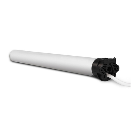
Motoriduttore tubolare per avvolgibili e tende da sole
ad uso intermittente (tempo di funzionamento: 4 minuti
prima dell’intervento del protettore termico).
Per la coppia di torsione occorre riferirsi a quanto indicato
nei dati di targa su ciascun modello. Verificare che la cop-
pia ed il tempo di funzionamento indicati sulla targa siano
compatibili con l’avvolgibile/tenda da motorizzare.
►INSTALLAZIONE (Fig. 1)
Per l’installazione, il motoriduttore deve essere completato con una
coppia di adattatori (corrispondenti con il rullo avvolgitore) e con una
piastra di sostegno. Per gli accessori vogliate riferirvi al ns. catalogo di
vendita.
ATTENZIONE: l’installazione non corretta può causare gravi feri-
te. Seguire tutte le istruzioni di installazione. Prima dell’instal-
lazione rimuovere tutti i cavi superflui e disattivare qualunque
apparecchiatura presente non necessaria per il funzionamento.
- Applicare gli adattatori sul motoriduttore distinguendo l’anello di
comando del finecorsa (Fig. 1.1 A) dalla puleggia motrice (Fig. 1.2 B).
- La piastra di sostegno del motoriduttore (C) va fissata all’interno del
cassonetto o sull’armatura della tenda in modo che il rullo avvolgito-
re (F) sia perfettamente in orizzontale ed ad un’altezza
non inferiore a 1,8m.
- Infilare il motoriduttore (E) nel rullo avvolgitore (F) fino a che
l’estremità dello stesso sia sulla battuta dell’anello di comando del
finecorsa (Fig. 1.3).
- [Per XQ 50] Appoggiare il perno quadro (D) del motoriduttore
nella piastra di sostegno (C) e la calotta all’estremità opposta del
rullo sull’apposito supporto.
ATTENZIONE: Non battere mai sul perno quadro del motore per
introdurlo nel tubo.
• Per la serie 50 con coppia nominale fino a 15 Nm il diametro
minimo del rullo avvolgitore è di 50x1,5mm; per coppie supe-
riori il diametro minimo è di 60x1,5mm.
• Per la serie 60 il diametro minimo del rullo avvolgitore è di
63x1,5mm.
ATTENZIONE:
- Le viti di fissaggio della stecca sul rullo, non devono toccare la
parte tubolare del motoriduttore. Vogliate utilizzare delle viti
adatte o le clips di fissaggio.
- Parti in movimento del motore montate al di sotto di una
altezza di 2,5m dal suolo devono essere protette.
- L’installazione inadeguata del motoriduttore può provocare
danni a persone o cose.
►COLLEGAMENTO ELETTRICO (Fig. 2)
Controllare che la tensione di rete disponibile sull’im-
pianto sia quella indicata sull’etichetta. Il collegamento alla
rete del motoriduttore deve essere eseguito, secondo lo schema a
pagina seguente, da tecnici qualificati in grado di operare nel rispetto
delle norme.
ATTENZIONE: Nella rete di alimentazione deve essere presente
un dispositivo di sezionamento con distanza di apertura tra i
contatti di almeno 3mm.
MOTORITUBOLARI CON FINECORSA ELETTRONICO
AD ENCODER - ISTRUZIONI
TUBULAR MOTORSWITH ENCODER ELECTRONIC
LIMITS - INSTRUCTIONS
MOTEURSTUBULAIRES AVEC FINS DE COURSES
ÉLECTRONIQUES À ENCODEUR - INSTRUCTIONS
ROHRMOTOREN MIT ELEKTRONISCHER ENDABSCHALTUNG UND
INTEGRIERTEM FUNKEMPFÄNGER - ANWEISUNGEN
MOTORESTUBULARES CON FINAL DE CARRERA ELECTRÓNICO
CON ENCODER - INSTRUCCIONES
IT
EN
FR
ES
DE
È IMPORTANTE PER LA SICUREZZA DELLE PERSONE SEGUIRE ATTENTAMENTE QUESTE ISTRUZIONI.
CONSERVARE QUESTE ISTRUZIONI. IMPORTANTE:
•Osservarel’avvolgibiledurantel’azionamentoetenerelontanelepersonenchèquestoèinmovimento.
•Esaminarefrequentementesevisonosbilanciamentiosegnidiusuraodanneggiamentodeicavi.Nonutilizzare
seviènecessitàdiriparazioneomanutenzione
•Nelcasodiutilizzosutendedasolecontrollarecheilcampodimovimentazionedellatendasialiberodaqualsiasi
oggettossoconunmarginedialmeno0,4m.
•L’apparecchiononèdestinatoadessereusatodapersone(bambinicompresi)lecuicapacitàsiche,sensoriali
omentalisianoridotte,oppureconmancanzadiesperienzao conoscenza,amenocheesse abbianopotuto
beneciare,attraversol’intermediazionediunapersonaresponsabiledellalorosicurezza,diunasorveglianzaodi
istruzioniriguardantil’usadell’apparecchio.
•Ibambini devonoesseresorvegliatiper sincerarsi chenongiochinoconl’apparecchioe/o conidispositividi
comandossi.
•Idispositividicontrolloinstallatiinmanierassadevonoessereposizionatiavista.
CAREFULLY FOLLOW THESE INSTRUCTIONS. IT IS VERY IMPORTANT FOR THE SAFETY OF PERSONS.
SAVE THESE INSTRUCTIONS. IMPORTANT:
•Checktheshutter/awninginmotionandkeeppersonsfarfromitwhileinaction.
•Frequentlycheckifanylossofbalance,signsofwearordamagedwiresareshown.
•Donotuseifanyrepairingormaintenanceisneeded.
•Incaseofinstallationinawningskeepadistanceofatleast0,4mfromit(completelyopen)andwhateverxed
iteminthenearby.
•Thedeviceisnotintendedtobeusedbypeople(includingchildren)whosephysical,sensoryormentalcapabili-
tiesarereduced,orlackingexperienceorknowledge,unlesstheyhavebeengrantedthroughtheintermediaryof
apersonresponsiblefortheirsafety,supervisionorinstructionconcerningtheuseofthedevice.
•Childrenshouldbesupervisedtoensuretheydonotplaywiththedeviceand/orwithxcontroldevices.
•Thecontroldevicesinstalledinaxedmannermustbepositionedinview.
IL EST IMPORTANT POUR LA SÉCURITÉ DES PERSONNES A SUIVRE ATTENTIVEMENT CES INSTRUCTIONS.
CONSERVER CE MANUEL. IMPORTANT:
•Suivrelevolet/storelorsdel’entraînementetleteniréloignédesgensjusqu’àcequ’ilestenmouvement.
•Examinerfréquemmentsi il ya des déséquilibres ou des signes d’usure ou de dommages aux câbles.Nepas
utilisersiilyabesoinderéparationoud’entretien.
•Encasd’utilisationdestorescontrôlerquelemouvementdustoresoitlibredetoutobjetxeavecunemarge
d’aumoins0,4m.
•L’appareiln’estpasdestinéàêtreutilisépardespersonnes(ycomprislesenfants)dontlescapacitésphysiques,
sensoriellesoumentalessontréduites,oulemanqued’expérienceoudeconnaissance,saufsiellesontbénécié,
parl’intermédiaired’une personneresponsabledeleur sécurité, de surveillanceoud’instructionsconcernant
l’utilisationdel’appareil.
•Lesenfantsdoiventêtresurveilléspours’assurerqu’ilsnejouentpasavecl’appareilet/oudesdispositifsdecontrôlexes.
•Lesdispositifsdecontrôleinstallésdemanièrexedoiventêtrepositionnésdemanièrequ’ilssoientvisibles.
ES IST SEHR WICHTIG FÜR DIE SICHERHEIT DER PERSONEN, DASS DIESE EINLEITUNGEN AUFMERKSAM BEFOLGT
SIND. DIESE EINBAUANLEITUNGEN AUFBEWAHREN. WICHTIG:
•BeachtenSiedenRollladenwährendderFahrtundPersonenfernhalten,biserinBewegungist.
•Esisthäugzukontrollieren,obesUngleichgewichte,VerschleißerscheinungenoderKabelbeschädigungengibt.
FürdenFall,dassReparaturenoderWartungennötigsind,betriebenSiedenMotornicht.
•FürdenEinsatzaufMarkisenisteinhorizontalerAbstandvonmindestens0,4mzwischendemvollständigausge-
rolltenangetriebenenTeilundjeglichemfestverlegtenGegenstandeinzuhalten.
•DasGerätistnichtzurVerwendungbestimmt,vonPersonen(einschließlichKinder),derenphysische,sensorische
odergeistige Fähigkeitenreduziert sind, oder vonPersonen,die an Erfahrungoder Kenntnis mangeln. Diese
KategorienvonPersonenbenötigenAufsichtundAnweisungenzurBenutzungdesSystemsdurchdieVermit-
tlungeinerPerson,dieverantwortlichfürihreSicherheitist.
•Kindersolltenbeaufsichtigtwerden,umsicherzustellen,dasssie nichtmitdemGerät und/oderfestenSteue-
reinrichtungenspielen.
•FestmontierteSteuereinrichtungenmüssensichtbarangebrachtwerden.
ES IMPORTANTE PARA LA SEGURIDAD DE LAS PERSONAS SEGUIR ATENTAMENTE ESTAS INSTRUCCIONES.
GUARDE ESTAS INSTRUCCIONES. IMPORTANTE:
•Observarlapersianaóeltoldoduranteelaccionamientoytenerlejosalaspersonasmientrasestaenmovimiento.
•Examinar frecuentementesi hay desequilibrioso daños de uso en elcable. No utilizar si se venecesidad de
sustituiroreparar.
•Enelcasodeutilizarsobretoldos,controlarqueelcampodemovimientodeltoldoestelibredecualquierobjeto
joconunmargendealmenos0,4m.
•Eldispositivonoestádestinadoaserutilizadoporpersonas(incluidosniños)cuyasfacultadesfísicas,sensoriales
o mentales sean reducidas, o con falta de experiencia o conocimiento, a menos que se les haya concedido
permiso,atravésdelamediacióndeunapersonaresponsabledesuseguridad,supervisadosoinstruidosacerca
delusodeldispositivo.
•Losniñosdebensersupervisadosparaasegurarsedequenojueguenconeldispositivoycondispositivosde
controljos.
•Losdispositivosdecontrolinstaladosdeformajadebenposicionarsedemaneraqueseanvisibile.
6ISTRE
I cavi di collegamento alla rete di questi motori possono essere
sostituiti soltanto con cavi dello stesso tipo forniti dal produttore dei
motori (Fig. 4).
- Se il motoriduttore gira in senso inverso (l’avvolgibile o tenda si
chiude con il comando apertura o viceversa) occorre invertire i
conduttori esterni.
- Non azionare l’avvolgibile/tenda quando si stanno compiendo delle
pulizie o manutenzione e scollegare l’alimentazione.
- L’interruttore che aziona l’apparecchio deve essere installato in vista
dell’automazione ad una altezza non superiore a 1,5 m e lontano da
parti in movimento.
►INFORMAZIONI IMPORTANTI PER GLI ELETTRICISTI
- Per il funzionamento normale del motore deve essere utilizzato solo
un interruttore standard che consente la SALITA o la DISCESA, ma
non contemporaneamente. Possono essere utilizzati solo interruttori
interbloccanti meccanicamente o elettricamente.
- I motori con finecorsa elettronici possono essere collegati in paralle-
lo. Il carico massimo dell’interruttore non si deve mai superare.
- Quando si inverte dalla SALITA alla DISCESA o viceversa, il tempo
di commutazione deve essere di almeno 0,5 secondi e si deve
passare attraverso una posizione OFF. Possono essere utilizzati solo
interruttori con una posizione neutra definita o con un ritardatore di
commutazione integrato.
- Centraline intelligenti che controllano l’assorbimento di corrente
sono in conflitto con il motore e non possono essere utilizzate.
►REGOLAZIONE FINECORSA (Fig. 3)
Il motoriduttore viene fornito con i finecorsa preregolati per circa due
giri in entrambi i sensi di rotazione.
IMPORTANTE: Le procedure di regolazione sotto indicate sono
valide sia con il motoriduttore a destra che a sinistra del rullo
avvolgitore.
►REGOLAZIONE TRAMITE PULSANTIERA ACPRE (opzionale) -
Fig. 3.1
IMPORTANTE: Il primo finecorsa da regolare è sempre quello di
SALITA
Caso 1.Sulla tapparella sono presenti i BLOCCHI DI SICUREZZA
(finecorsa fisico)
- Collegare il motore alla pulsantiera di regolazione ACPRE;
- Premere i 2 pulsanti contemporaneamente per 15 secondi, il motore
si muove brevemente nei due sensi di rotazione per circa 1 secondo.
- Premere sul pulsante di SALITA e fare arrivare la tapparella sul blocco
di sicurezza SALITA, in questo modo il finecorsa salita è regolato;
- Premere sul pulsante DISCESA e regolare il finecorsa DISCESA con
l’aiuto della pulsantiera;
- Premere i 2 pulsanti contemporaneamente per 15 secondi, il motore
si muove brevemente nei due sensi di rotazione per circa 1 secondo.
In questo modo il finecorsa DISCESA è regolato.
- Scollegare la pulsantiera ACPRE e collegare la pulsantiera standard.
Caso 2. Sulla tapparella non sono presenti i BLOCCHI DI
SICUREZZA (finecorsa virtuale)
- Collegare il motore alla pulsantiera di regolazione ACPRE;
- Premere i 2 pulsanti contemporaneamente per 15 secondi, il motore
si muove brevemente nei due sensi di rotazione per circa 1 secondo.
- Premere sul pulsante SALITA e regolare il finecorsa SALITA con l’aiuto
della pulsantiera;
- Premere i 2 pulsanti contemporaneamente per 15 secondi, il motore
si muove brevemente nei due sensi di rotazione per circa 1 secondo.
In questo modo il finecorsa SALITA è regolato.
- Premere sul pulsante DISCESA e regolare il finecorsa DISCESA con
l’aiuto della pulsantiera;
- Premere i 2 pulsanti contemporaneamente per 15 secondi, il motore
si muove brevemente nei due sensi di rotazione per circa 1 secondo.
In questo modo il finecorsa DISCESA è regolato.
- Scollegare la pulsantiera ACPRE e collegare la pulsantiera standard.
►REGOLAZIONE TRAMITE PULSANTIERA STANDARD
Fig. 3.2 [solo per XQ50]
Caso 1. Sulla tapparella sono presenti i BLOCCHI DI SICUREZZA
(finecorsa fisico)
- Premere il pulsante bianco che si trova sulla testa motore e uno dei
2 pulsanti della pulsantiera standard per 15 secondi, il motore si
muove brevemente nei due sensi di rotazione per circa 1 secondo.
- Premere sul pulsante di SALITA e fare arrivare la tapparella sul blocco
di sicurezza SALITA, in questo modo il finecorsa salita è regolato;
- Premere sul pulsante DISCESA e regolare il finecorsa DISCESA con
l’aiuto della pulsantiera;
- Premere il pulsante bianco che si trova sulla testa motore e uno dei
2 pulsanti della pulsantiera standard per 15 secondi, il motore si
muove brevemente nei due sensi di rotazione per circa 1 secondo.
In questo modo il finecorsa DISCESA è regolato.
Caso 2. Sulla tapparella non sono presenti i BLOCCHI DI
SICUREZZA (finecorsa virtuale)
- Premere il pulsante bianco che si trova sulla testa motore e uno dei
2 pulsanti della pulsantiera standard per 15 secondi, il motore si
muove brevemente nei due sensi di rotazione per circa 1 secondo.
- Premere sul pulsante SALITA e regolare il finecorsa SALITA
con l’aiuto della pulsantiera;
- Premere il pulsante bianco che si trova sulla testa motore e uno dei
2 pulsanti della pulsantiera standard per 15 secondi, il motore si
muove brevemente nei due sensi di rotazione per circa 1 secondo.
In questo modo il finecorsa SALITA è
regolato.
- Premere sul pulsante DISCESA e regolare il finecorsa DISCESA
con l’aiuto della pulsantiera;
- Premere il pulsante bianco che si trova sulla testa motore e uno dei
2 pulsanti della pulsantiera standard per 15 secondi, il motore si
muove brevemente nei due sensi di rotazione per circa 1 secondo.
In questo modo il finecorsa DISCESA è regolato.
IT
GAPOSA srl - via Ete, 90 - 63900 Fermo - Italy - T. +39.0734.220701 - F. +39.0734.226389
[email protected] - www.gaposa.com
4x0.75 mm2 /4x18 AWG
Neutro-Neutral
Neutre-Neutral
Neutral
Terra-Ground
Terre-Erde
Tierra
Fase-Phase-Phase-Phase-Leitung
P
Pulsantiera
Pushbutton
Inverseur
Drucktaste
Pulsador
230 V~ / 50 Hz 120 V~ / 60 Hz
Neutro-Neutral-Neutre-Neutral-Neutral Blu-Blue-Bleu
Blau-Azul
Bianco-White-Blanc
Weiß-Blanco
Terra-Ground-Terre-Erde-Tierra
Giallo/Verde-Yellow/Green
Jaune/Vert-Gelb/Grün
Amarillo/Verde
Verde-Green-Vert
Grün-Verde
Versorotazione1-Directionofrotation1-Sensde
rotation1-Sentidoderotación1-Drehrichtung1
Marrone-Brown
Marron-Braun-Marrón
Rosso-Red-Rouge
Rot-Rojo
Versorotazione2-Directionofrotation2-Sensde
rotation2-Sentidoderotación2-Drehrichtung2
Nero-Black-Noir
Schwarz-Negro
Nero-Black-Noir
Schwarz-Negro
Controllare che la tensione di rete disponibile sull’impian-
to sia quella indicata sull’etichetta.
Check that the power supply corresponds to the label data.
Verifiez que la tension d’alimentation disponible est celle
indiquée sur l’etiquette.
Prüfen Sie, ob die auf dem Klebezettel angegebene
Spannung der Netzversorgung entspricht.
Controlar che la tensión de alimentación sea la indicada
en la etiqueta.
Fig. 2
P
Alimentazione
Powersupply
Alimentation
Versorgung
Alimentacción
Pulsantiera
Pushbutton
Inverseur
Drucktaste
Pulsador
Fig. 4
230 V~ / 50 Hz
120 V~ / 60 Hz (ver. U)
Alimentazione / Power supply
Alimentation / Versorgung
Alimentacción
Fig. 3.1
S
T
O
P
ST
OP
ACPRE
Fig. 3.2
Fig. 3
Fig. 1
Fig. 1.1
Fig. 1.2
Fig. 1.3
B
A
E
F
F
90°
min 1,8 m
C
D
►DESCRIPTION
Motoréducteur tubulaire pour volet/store/rideau à usage intermittent (temps de fonction-
nement: 4 minutes avant l’intervention du protecteur thermique). Pour le couple de torsion
il faut se référer à ce qu’il est indiqué sur l’étiquette de chaque modèle. Il faut vérifier que le
couple et le temps de fonctionnement indiqués sur l’étiquette soient compatibles avec le
volet/store/rideau à motoriser.
►INSTALLATION (Fig. 1)
Pour l’installation, le motoréducteur doit être pourvu d’un jeu d’adaptateurs (correspondants avec le tube)
et d’un support. Pour les accessoires veuillez consulter notre catalogue de vente.
ATTENTION: une installation non correcte peut causer de graves accidents. Suivez toutes les in-
structions d’installation. Avant l’installation il faut éliminer tous les câbles inutiles et désactiver
tout appareillage présent et qui n’est pas nécessaire pour le fonctionnement.
- Insérez les adaptateurs sur le motoréducteur en distinguant la bague de la fin de course
(Fig. 1.1 A) de la couronne d’entraînement (Fig. 1.2 B).
- Le support du motoréducteur (C) doit être fixé à l’intérieur du caisson ou sur l’armature du store de
manière que le tube (F) soit en position parfaitement horizontale et à une hauteur non inférieure à 1,8m.
- Insérez le motoréducteur (E) dans le tube (F) jusqu’à ce que l’extrémité de cela soit sur la butée de la
bague du fin de course (A) (Fig. 1.3).
- [Pour XQ50] Insérez le carré de soutien (D) du motoréducteur dans le support (C) et l’embout dans
l’extrémité opposée du tube, dans son support.
ATTENTION: ne frappez jamais le carré du moteur pour l’introduire dans le tube.
• Pour la série 50, avec couple jusqu’à 15Nm, le diamètre min. du tube est de 50x1,5mm; pour
couples plus élevés, le diamètre min. est de 60x1,5mm.
• Pour la série 60, le diamètre min. du tube est de 63x1,5mm.
ATTENTION:
- Les vis de fixation de la lame au tube ne doivent en aucun cas toucher le corps du moteur.
Utiliser des vis courtes ou des agrafes de fixation.
- Il faut protéger toutes les parties en mouvement du moteur qui se trouvent au-dessous de
2,5m de terre. Une installation inadéquate du motoréducteur peut causer des dommages aux
personnes et aux éléments extérieurs.
►BRANCHEMENT ELECTRIQUE (Fig. 2)
Vérier que la tension d’alimentation disponible est celle indiquée sur l’étiquette.
Le branchement du motoréducteur au réseau de l’alimentation doit être exécuté selon le schéma à la page
qui suit, par des techniciens qualifiés capables d’opérer en respectant les normes.
ATTENTION: le réseau de l’alimentation doit être pourvu d’un dispositif de sectionnement et la
distance d’ouverture entre les contacts doit être d’au moins 3mm.
Les câbles de raccordement au réseau de ces moteurs ne peuvent être remplacés que par des câbles du
même type fourni par le fabricant du moteur (Fig. 4).
- Si le motoréducteur tourne dans le sens inverse (le volet/store/rideau se ferme à la commande d’ouver-
ture ou le contraire) il faut inverser les fils externes.
- Ne jamais actionner le volet/store/rideau pendant le nettoyage ou l’entretien du dispositif et déconnec-
tez l’alimentation.
- Le bouton qui actionne le dispositif doit être installé en vue, à une hauteur non supérieure à 1,5m et à
l’écart d’objets en mouvement.
►INFORMATIONS IMPORTANTES POUR LES ÉLECTRICIENS
- Pour un fonctionnement normal du moteur il faut utiliser uniquement un inverseur standard qui permet
la MONTÉE ou la DESCENTE, jamais les deux en même temps. Nous pouvons utiliser seulement des
inverseurs inter-verrouillés mécaniquement ou électriquement.
- Les moteurs avec fins de courses électroniques peuvent être connectés en parallèle. La charge maximale
de l’inverseur ne doit jamais être dépassée.
- Lorsque vous inversez le sens de rotation, le temps de commutation doit être d’au moins 5 secondes et
il faut passer par une position OFF. Nous pouvons utiliser uniquement des inverseurs avec une position
neutre définie ou avec un temporisateur de commutation intégré.
- Armoires “intelligentes” qui contrôlent l’inversion de courant sont en conflit avec le moteur et ne peuvent
pas être utilisées.
►RÉGLAGE DES FINS DE COURSES - FDC (Fig. 3)
Le motoréducteur est livré avec les fins de courses préréglés à environs deux tours dans chaque sens de
rotation.
IMPORTANT: Les procédures de réglage qui suivent sont valables pour l’installation du mo-
toréducteur à droite ou à gauche du tube.
►RÉGLAGE PAR ACPRE (optionnelle) - Fig. 3.1
IMPORTANT: Le premier fin de course à régler est toujours celui de MONTEE
Cas 1. Le volet est équipé de VERROUS AUTOMATIQUES
- Brancher le moteur à l’outil de reglage ACPRE;
- Appuyer sur les deux boutons pendant 15 Sec > Bref mouvement du moteur dans les deux sens de
rotation pendant 1S
- Appuyer sur le bouton MONTÉE en venant faire buter la lame finale sur la butée haute. Le FDC HAUT est réglé;
- Appuyer sur le bouton DESCENTE et ajuster la position bas à l’aide de l’inverseur;
- Appuyer sur les deux boutons pendant 15S > Bref mouvement du moteur dans les deux sens de rotation
pendant 1S > Le FDC BAS est réglé.
- Débranchez la ACPRE et connecter l’inverseur standard.
Cas 2. Le volet n’est pas équipé de VERROUS AUTOMATIQUES
- Brancher le moteur à l’outil de reglage ACPRE;
- Appuyer sur les deux boutons pendant 15 Sec > Bref mouvement du moteur dans les deux sens de
rotation pendant 1S
- Appuyer sur le bouton MONTÉE et ajuster la position haute à l’aide de l’inverseur;
- Appuyer sur les deux boutons pendant 15S.
- Appuyer sur le bouton MONTÉE et ajuster la position haute à l’aide de l’inverseur > Bref mouvement du
moteur dans les deux sens de rotation pendant 1S > le FDC HAUT est réglé.
- Appuyer sur le bouton DESCENTE et ajuster la position bas à l’aide de l’inverseur;
- Appuyer sur les deux boutons pendant 15S > Bref mouvement du moteur dans les deux sens de rotation
pendant 1S > le FDC BAS est réglé.
- Débranchez la ACPRE et connecter l’inverseur standard.
►RÉGLAGE PAR INVERSEUR STANDARD - Fig. 3.2 [uniquement pour XQ50]
Cas 1. Le volet est équipé de VERROUS AUTOMATIQUES
- Appuyer sur le Bouton BLANC qui se trouve sur la tête moteur et appuyer en même temps sur l’un des
deux boutons de l’interrupteur pendant 15S > Bref mouvement du moteur dans les deux sens de rotation
pendant 1S.
- Appuyer sur le bouton MONTÉE en venant faire buter la lame finale sur la butée haute > le FDC HAUT est réglé
- Appuyer sur le bouton DESCENTE et ajuster la position bas à l’aide de l’inverseur;
- Appuyer sur le bouton BLANC qui se trouve sur la tête moteur et appuyer en même temps sur l’un
des deux boutons de l’interrupteur pendant 15S > Bref mouvement du moteur dans les deux sens de
rotation pendant 1S > le fin de course BAS est réglé.
Cas 2. Le volet n’est pas équipé de VERROUS AUTOMATIQUES
- Appuyer sur le Bouton BLANC qui se trouve sur la tête moteur et appuyer en même temps sur l’un des
deux boutons de l’interrupteur pendant 15S > Bref mouvement du moteur dans les deux sens de rotation
pendant 1S.
- Appuyer sur le bouton MONTÉE et ajuster la position haute à l’aide de l’inverseur;
- Appuyer sur le Bouton BLANC qui se trouve sur la tête moteur et appuyer en même temps sur l’un
des deux boutons de l’interrupteur pendant 15S > Bref mouvement du moteur dans les deux sens de
rotation pendant 1S > le fin de course HAUT est réglé.
- Appuyer sur le bouton DESCENTE et ajuster la position bas à l’aide de l’inverseur;
- Appuyer sur le Bouton BLANC qui se trouve sur la tête moteur et appuyer en même temps sur l’un des
deux boutons de l’interrupteur pendant 15S > Bref mouvement du moteur dans les deux sens de rotation
pendant 1S > le fin de course BAS est réglé.
►DESCRIPTION
Tubular motor for roller shutters and awnings for intermittent use (working time: 4 minutes
before the thermal protector intervention). The torque of each model is indicated on the
relative label. Check that torque and working time stated on the label are compatible with the
shutter/awning that must be motorized.
►INSTALLATION (Fig. 1)
To complete installation, the motor must be provided with a couple of adaptors (corresponding with the
tube) and a fixing bracket. For a list of the available accessories, refer to the catalogue.
WARNING: incorrect installation can cause serious injuries. Follow the installation instructions.
Before installation, remove all unnecessary cables and turn off any equipment not required for
this operation.
- Fix the adaptors to the motor distinguishing the limits ring (Fig. 1.1 A) from the drive pulley
(Fig. 1.2 B).
- Turn and lock the clip after inserting it in the drive-shaft groove.
- The fixing bracket (C) must be fixed inside the box or on the awning frame so that the roller tube (F) is
perfectly horizontal and at a height not less than 1,8m.
- Insert the motor (E) into the tube (F) until its end stops against the limits ring.
- [For XQ50] Place the motor square pin (D) on the bracket (C) and the cap at the opposite end of the
tube on the fixing plate.
WARNING: Never hit on the head of the motor (D) when you insert it into the tube.
• For the 50 range, with torque up to 15Nm, the minimum tube diameter is 50x1,5mm; for
motors with higher torques, the minimum tube diameter is 60x1,5mm.
• For the 60 range, the minimum tube diameter is 63x1,5mm.
WARNING: The screws used to fix the last slat on the tube may be too long and reach the tubular
part of the motor. Use appropriate screws or fixing clips. Motor moving parts installed under
2,5m from the ground must be protected. A wrong motor installation can damage persons or
objects.
►ELECTRICAL CONNECTION (Fig. 2)
Check that the mains voltage available on the system is as shown on the label.
The motor mains connection should be executed according to the diagram on the next page, by qualified
technicians able to operate in compliance with the rules.
ATTENTION: The power supply must contemplate a switching device with an opening distance
between contacts of at least 3mm.
The motors connecting cables to the network can only be replaced with cables of the same type provided
by the motor manufacturer (Fig. 4).
- If the motor runs the wrong way round (es.: the shutter/awning closes with the up control or the other
way round) the external cables must be reversed.
- Do not set the shutter/awning into motion while you are cleaning or servicing the device and disconnect
the supply.
- The switch controlling the motor must be installed in full view, not higher than 1,5m and it must be kept
far from moving parts.
►IMPORTANT INFORMATION FOR ELECTRICIANS
- For standard motor operation only a standard switch allowing either UP or DOWN but not both at the
same time must be used. Only mechanically or electrically interlocked switches can be used.
- Motors with electronic limits can be connected in parallel. The maximum load of the switch must never
be exceeded.
- When changing from UP to DOWN or vice versa, the switchover time must at least be 0.5 seconds and
effected through an OFF position. Only switches with a defined neutral position or one with a built-in
switching delay should be used.
- An “active path” control unit which monitors the current draw is in conflict with the motor and cannot be
used.
►SETTING THE LIMITS (Fig. 3)
Motors are supplied with pre-set limit switches, in order to allow two turns in both directions.
IMPORTANT: Limit-switches setting procedures shown are valid for right and left side installa-
tion.
►SETTING WITH PUSHBUTTON TOOL ACPRE (option) - Fig. 3.1
Always set the UP limit switch FIRST
Case 1. Shutter with mechanical stops or cassette awnings
- Connect the motor to the pushbutton ACPRE;
- Press Up and Down buttons simultaneously until the motor jogs.
- Press the Up button and release it only when the motor stops because the shutter/awning has reached
the Up stops. Up limit switch is set;
- Press the Down button and release it only when the shutter/awning has reached the desired limit switch
position.
- Press Up and Down buttons simultaneously until the motor jogs. Down limit switch is set;
- Disconnect the setting pushbutton tool ACPRE and connect the motor to the final standard pushbutton.
Case 2. Shutter or awnings without stops
- Connect the motor to the pushbutton ACPRE;
- Press Up and Down buttons simultaneously until the motor jogs.
- Press the Up button and release it when the shutter/awning has reached the desired limit switch position;
- Press Up & Down buttons simultaneously until the motor jogs. Up limit switch is set.
- Press the Down button and release it only when the shutter/awning has reached the desired limit switch
position.
- Press Up and Down buttons simultaneously until the motor jogs. Down limit switch is set;
- Disconnect the setting pushbutton tool ACPRE and connect the motor to the final standard pushbutton.
► SETTING WITH STANDARD PUSHBUTTON - Fig. 3.2 [only for XQ50]
Case 1. Shutter with mechanical stops or cassette awnings
- Press the white button on the motor head together with one of the two pushbuttons until the motor
jogs.
- Press the Up button and release it only when the motor stops because the shutter/awning has reached
the Up stops. Up limit switch is set;
- Press the Down button and release it only when the shutter/awning has reached the desired limit switch
position.
- Press Up and Down buttons simultaneously until the motor jogs. Down limit switch is set;
Case 2. Shutter or awnings without stops
- Press the white button on the motor head together with one of the two pushbuttons until the motor jogs.
- Press the Up button and release it when the shutter/awning has reached the desired limit switch position;
- Press the white button on the motor head together with one of the two pushbuttons until the motor
jogs. The Up limit switch is set.
- Press the Down button and release it only when the shutter/awning has reached the desired limit switch
position. Press Up or Down button to find the exact final position.
- Press the white button on the motor head together with one of the two pushbuttons until the motor
jogs. The Down limit switch is set;
FREN
► DESCRIPCIÓN
Motor tubular para persianas y toldos de uso intermitente (tiempo de funcionamiento: 4
minutos antes de la intervención de la protección térmica). Para la fuerza de levantamiento
referirse a la tabla de selección de cada modelo. Verificar que la fuerza y el tiempo de funcio-
namiento indicado sobre la tabla son compatibles con la persiana o toldo a motorizar.
► INSTALACION (Fig. 1)
Para instalar el motor son necesarios dos adaptadores (controlando que se correspondan con el tubo) y un
soporte. Para un listado de los accesorios referirse al catalogo.
ATENCIÓN: Una instalación incorrecta puede ocasionar graves accidentes. Seguir todas las
instrucciones de la instalación.
Antes de la instalación apartar y desactivar todos los cables que no sean necesarios para el
funcionamiento.
- Aplicar los adaptadores al motor distinguiendo el anillo del final de carrera (Fig. 1.1 A) de la polea motriz
(Fig. 1.2 B).
- El soporte del motor (C) va fijado al interior del cajón o sobre la armadura del toldo de manera que el
tubo (F) sea perfectamente horizontal y a una altura no inferior a 1,8m.
- Insertar el motor (E) en el tubo (F) hasta que la extremidad del mismo llegue al tope del anillo del final de
carrera (Fig. 1.3).
- [Para XQ50] Apoyar el perno cuadrado del motor (D) en el soporte (C) y la tapa a la extremidad opuesta
del tubo en el soporte adecuado.
ATENCIÓN: No golpear nunca el perno cuadrado del motor (D) para introducirlo en el tubo.
• Para la serie 50 con par nominal hasta 15Nm el diámetro mínimo del rulo es de 50x1,5mm; para
un par superior el diámetro mínimo es de 60x1,5mm.
• Para la serie 60 el diámetro mínimo del rulo es de 63x1,5mm.
ATENCIÓN:
- La sujeción al tubo de los tirantes de la persiana debe realizarse mediante tirantes de clips ó
con tornillos específicos con un largo que no dañe la carcasa del motor.
- Las partes de movimiento del motor montadas por debajo de una altura de 2,5m del suelo
debe ser protegidas.
- La instalación inadecuada del motor puede provocar daños a personas o cosas.
► CONEXION ELECTRICA (Fig. 2)
Controlar que la tensión de alimentación disponible en la instalación sea la indicada en
la etiqueta. La conexión del motor a la línea eléctrica se debe realizar, según lo que indica el esquema
siguiente, por técnicos cualificados capaces de respetar las normas.
ATENCIÓN: En la red de alimentación debe de ser presente un dispositivo de corte con una
distancia mínima entre contactos de almenos 3 mm.
Los cables de conexión a la red de estos motores sólo se pueden sustituir por cables del mismo tipo
proporcionado por el fabricante del motor (Fig. 4).
- Si el motoreductor gira en sentido inverso (persiana o toldo se cierra con el mando subida o viceversa) es
necesario invertir los conductores externos.
- No accionar la persiana o toldo cuando se esta procediendo a la limpieza o mantenimiento del mismo,
para lo cual se debe desconectar la alimentación.
- El interruptor que acciona la instalación debe ser instalado a la vista del automatismo y de una altura no
superior a 1,5 m y lejos de partes en movimiento.
► INFORMACIÓN IMPORTANTE PARA INSTALADORES.
- Para el funcionamiento normal del motor sólo se debe utilizar un interruptor estándar que permite la
SUBIDA o la BAJADA, pero no simultáneamente. Sólo pueden utilizarse interruptores con interbloqueo
mecánico o eléctrico.
- Los motores con finales de carrera electrónicos se pueden conectar en paralelo. La carga máxima del
interruptor no debe ser superada nunca.
- Cuando se invierte desde la SUBIDA a la BAJADA o viceversa, el tiempo de conmutación debe ser de
al menos 0,5 segundos, y usted tiene que ir a través de una posición de apagado OFF. Sólo se pueden
utilizar interruptores con una posición neutra definida o con un sistema incorporado de retardo de
conmutación.
- Controles inteligentes que controlan el consumo de corriente están en conflicto con el motor y no se
pueden utilizar.
► REGULACION DE LOS FINALES DE CARRERAS - FDC (Fig. 3)
El motor viene equipado con los finales de carrera preregulados cerca de dos vueltas en los dos sentidos
de rotación.
IMPORTANTE: El procedimiento de regulación indicado a continuación es vàlido ya sea con el
motor a la izquierda o a la derecha del tubo.
►REGULACION A TRAVÉS DE ACPRE (opcional) - Fig. 3.1
IMPORTANTE: Siempre se debe reglar el FDC de SUBIDA en primer lugar.
Caso 1. PERSIANA CON BLOQUEOS MECÁNICOS O TOLDO CON CAJÓN
- Conectar el motor al pulsador de programación ACPRE;
- Presionar simulteneamente los 2 botónes durante 15S hasta que el motor no se mueva en ambos sentidos.
- Mantener presionado el botón SUBIDA y esperar que el motor llega a los bloqueos. Después soltar el
botón > el FDC SUBIDA ha sido reglado;
- Mantener presionado el botón BAJADA hasta que el motor llega a la posición del FDC deseada;
- Presionar simulteneamente los 2 botónes durante 15S hasta que el motor no se mueva en ambos senti-
dos > el FDC de BAJADA ha sido reglado.
- Desactivar el pulsador ACPRE y conectar el pulsador definitivo.
Caso 2. PERSIANA O TOLDO SIN BLOQUEOS
- Conectar el motor al pulsador de programación ACPRE;
- Presionar simulteneamente los 2 botónes durante 15S hasta que el motor no se mueva en ambos sentidos.
- Mantener presionado el botón SUBIDA hasta que el motor llega a la posición del FDC deseada;
- Presionar simultaneamente los 2 botónes durante 15S hasta que el motor no se mueva en ambos senti-
dos > el FDC SUBIDA ha sido reglado.
- Mantener presionado el botón BAJADA hasta que el motor llega a la posición del FDC deseada.
- Presionar simulteneamente los 2 botónes durante 15S hasta que el motor no se mueva en ambos senti-
dos > el FDC BAJADA ha sido reglado.
- Desactivar el pulsador ACPRE y conectar el pulsador definitivo.
► REGULACION A TRAVÉS PULSADOR STANDARD - Fig. 3.2 [sólo para XQ50]
Caso 1. PERSIANA CON BLOQUEOS MECÁNICOS O TOLDO CON CAJÓN
- Mantener presionado el botón BLANCO sobre el testero del motor e después, presionar uno de los dos
botónes del pulsador durante 15S hasta que el motor no se mueva en ambos sentidos. Después soltar
ambos los botónes.
- Mantener presionado el botón SUBIDA y esperar que el motor llega a los bloqueos. Después soltar el
botón > el FDC de SUBIDA ha sido reglado;
- Mantener presionado el botón BAJADA hasta que el motor llega a la posición del FDC deseada. Reglar la
posición exacta a través de los botónes;
- Mantener presionado el botón BLANCO sobre el testero del motor e después, presionar uno de los dos
botones del pulsador durante 15S hasta que el motor no se mueva enambos sentidos. Después soltar los
botónes > FDC reglado.
Caso 2. PERSIANA O TOLDO SIN BLOQUEOS
- Mantener presionado el botón BLANCO sobre el testero del motor e después, presionar uno de los dos
botónes del pulsador durante 15S hasta que el motor no se mueva en ambos sentidos. Después soltar
ambos los botónes.
- Mantener presionado el botón SUBIDA hasta que el motor llega a la posición del FDC deseada;
- Presionar el botón BLANCO sobre el testero del motor e después, presionar uno de los dos botónes del
pulsador durante 15S hasta que el motor se mueva en ambos sentidos. Después soltar el botón > el FDC
SUBIDA ha sido reglado.
- Mantener presionado el botón BAJADA hasta que el motor llega a la posición del FDC deseada. Reglar la
posición exacta a través de los botónes;
- Mantener presionado el botón BLANCO sobre el testero del motor e después, presionar uno de los dos
botones del pulsador durante 15S hasta que el motor no se mueva en ambos sentidos. Después soltar los
botónes > FDC reglado.
ES
DE
► BESCHREIBUNG
Rohrgetriebemotor für Rollläden und Markisen, der für den Kurzzeitbetrieb ausgelegt ist.
(Betriebszeit: 4 Minuten vor Thermoschalter). Das Drehmoment steht auf dem Etikett. Über-
prüfen Sie bitte, dass Drehmoment und Betriebszeit auf dem Etikett kompatibel mit dem zu
motorisierenden Rollladen/der Markise sind.
► INSTALLATION (Fig. 1)
Für die Installation versehen Sie den Motor mit einem Adapter (1xMitnehmer und 1xWellenkupplung) und
einem Motorlager. Eine Liste der Zubehörteile finden Sie in dem Verkaufskatalog.
VORSICHT: Eine falsche Installation kann schwere Unfälle verursachen. Befolgen Sie alle nachfol-
gende Anweisungen.
Vor der Installation muss man alle unnötige Kabel entfernen und jede unnötige anwesende
Einrichtung ausschalten.
- Adapter am Motor befestigen: der Endschalterring (Fig. 1.1 A) ist von der Wellenkupplung
(Fig. 1.2 B) zu unterscheiden.
- Die Befestigungsklipp in der Achse einführen und umdrehen bis sie sich ineinander genau fügen.
- Der Getriebemotor (E) in das Rohr (F) einführen, bis sein Ende am Anschlag des Endschalterrings anliegt
(Fig. 1.3).
- [Für XQ50] Der Motorvierkantstift (D) in das Befestigungslager (C) und die Kappe in das vorgesehenen
Lager am entgegensetzten des Rohres stecken.
VORSICHT: nie auf den Vierkantstift (D) schlagen, um ihn in das Rohr einzuführen.
• XQ 50 (Drehmoment bis 15Nm): Rohrmindestdurchmesser = 50x1,5mm;
• Serie 50 (Drehmoment > 15Nm): Rohrmindestdurchmesser = 60x1,5mm;
• XQ 60: Rohrmindestdurchmesser = 63x1,5mm.
VORSICHT:
- Die Schrauben zur Befestigung des Stabs auf der Welle dürfen das Rohr des Motors nicht
berühren. Benutzen Sie bitte geeigneten Schrauben oder Befestigungsklipps.
- Bewegende Motorteile, die unter einer Höhe von 2,5 m vom Boden montiert sind, müssen
geschützt sein.
- Eine falsche Installation kann Personen- und Sacheschaden verursachen.
► ELEKTRISCHE VERBINDUNG (Fig. 2)
Nachprüfen, dass die auf dem Klebezettel angegebene Spannung der Netzspannung
entspricht. Der elektrische Anschluss des Motors muss nach dem Schema auf der folgenden Seite von
qualifizierten Technikern gemäß allen Normen ausgeführt werden.
VORSICHT: Das Netz muss mit einer Trennvorrichtung mit einer Kontaktöffnungsweite von
mindestens 3 mm versehen sein.
Die Netzanschlussleitung dieses Antriebs darf nur durch den gleichen Leitungstyp, geliefert vom Hersteller
des Antriebs, ersetzt werden (Fig. 4).
- Falls sich der Motor in die falsche Richtung dreht (der Rollladen oderdie Markise schließen sich infolge
von einem Befehl in Auf-Richtung oder umgekehrt), ist es nötig, den externen Faden umzustellen.
- Nicht der Rollladen /die Markise während der Säuberung oder der Wartungsarbeit betreiben und immer
die Versorgung ausschalten.
- Der Schalter muss in Sicht, unter einer Höhe von 1,5m und weit von bewegenden Gegenstände montiert
werden.
► WICHTIGE INFORMATIONEN FÜR DEN ELEKTROINSTALLATEUR
- Für den normalen Betrieb des Motors darf nur ein Schalter verwendet werden, der den AUF oder AB
Betrieb erlaubt, aber nicht gleichzeitig. Es dürfen nur mechanische oder elektrische verriegelte Schalter
verwendet werden.
- Motoren mit elektronischer Endabschaltung können parallelgeschaltet werden. Die maximale Belastung
des Schalters darf niemals überschritten werden.
- Zwischen einem AUF- und einem AB- Befehl oder umgekehrt, muß die Schaltzeit mindestens 0,5 Sekun-
den dauern, und sie muß eine OFF-Position durchlaufen. Es können nur Schalter mit einer definierten
neutralen Position oder mit einer integrierten Schaltverzögerung verwendet werden.
- Intelligente Steuerungen, die den Stromverbrauch kontrollieren, stehen im Konflikt mit dem Motor und
können nicht verwendet werden.
► EINSTELLVORGANG (Fig. 3)
Der Getriebemotor wird mit voreingestellten Endschaltern geliefert, um ca.2 Umdrehungen in beide
Drehrichtungen zu ermöglichen.
WICHTIG: Die unten angeführten Verfahren gelten sowohl für Motoreinbau an der linken als
auch an der rechten Seite der Welle.
►EINSTELLUNG DURCH DEN JUSTIERSCHALTER ACPRE (option) - Fig. 3.1
WICHTIG: OBERE ENDLAGE immer zuerst einstellen
Möglichkeit 1. Rollläden mit ANSCHLAG (physikalische Endlage)
- Den Antrieb mit dem ACPRE Justierschalter verbinden;
- Beide Tasten gleichzeitig für ca. 15 Sek. lang drücken bis der Motor für ca. 1 Sek. kurz in beiden
Drehrichtungen fährt.
- AUF-Taste drücken und gedrückt halten bis der Rollladen den Anschlag erreicht. OBERE Endlage ist
eingestellt;
- AB-Taste drücken und durch den Justierschalter die UNTERE gewünschte Endlageposition finden;
- Beide Tasten gleichzeitig 15 Sek. lang drücken bis der Antrieb für ca. 1 Sek. kurz in beiden Drehrichtun-
gen fährt. UNTERE Endlage ist eingestellt.
- Der ACPRE Justierschalter abschalten und die Standard Schalter verbinden.
Möglichkeit 2. Rollläden ohne ANSCHLAG (virtuelle Endlage)
- Den Antrieb mit dem ACPRE Justierschalter verbinden;
- Beide Tasten gleichzeitig für ca. 15 Sek. lang drücken bis der Motor für ca. 1 Sek. kurz in beiden
Drehrichtungen fährt.
- AUF-Taste drücken und die OBERE Endlage durch den Justierschalter einstellen;
- Beide Tasten gleichzeitig 15 Sek. lang drücken bis der Antrieb für ca. 1 Sek. kurz in beiden Drehrichtun-
gen fährt. Die OBERE Endlage ist eingestellt.
- AB-Taste drücken und durch den Justierschalter die UNTERE gewünschte Endlageposition finden;
- Beide Tasten gleichzeitig 15 Sek. lang drücken bis der Antrieb für ca. 1 Sek. kurz in beiden Drehrichtun-
gen fährt. Die UNTERE Endlage ist eingestellt.
- Der ACPRE Justierschalter abschalten und die Standard Schalter verbinden.
►EINSTELLUNG DURCH DEN STANDARDSCHALTER - Fig. 3.2 [nur für XQ50]
Möglichkeit 1. Rollläden mit ANSCHLAG (physikalische Endlage)
- Drücken Sie die weiße Taste auf dem Motorkopf und einen der zwei Tasten des Standardschalters für ca.
15 Sek. lang: der Motor fährt für ca. 1 Sek. kurz in beiden Drehrichtungen.
- AUF-Taste drücken und gedrückt halten bis der Rollladen den Anschlag erreicht. OBERE Endlage ist
eingestellt;
- AB-Taste drücken und durch den Standardschalter die UNTERE gewünschte Endlageposition finden;
- Drücken Sie die weiße Taste auf dem Motorkopf und einen der zwei Tasten des Standardschalters für
ca. 15 Sek. lang: der Motor fährt für ca. 1 Sek. kurz in beiden Drehrichtungen. Die UNTERE Endlage ist
eingestellt.
Möglichkeit 2. Rollläden ohne ANSCHLAG (virtuelle Endlage)
- Drücken Sie die weiße Taste auf dem Motorkopf und einen der zwei Tasten des Standardschalters für ca.
15 Sek. lang: der Motor fährt für ca. 1 Sek. kurz in beiden Drehrichtungen.
- AUF-Taste drücken und die OBERE Endlage durch den Standardschalter einstellen;
- Drücken Sie die weiße Taste auf dem Motorkopf und einen der zwei Tasten des Standardschalters für
ca. 15 Sek. lang: der Motor fährt für ca. 1 Sek. kurz in beiden Drehrichtungen. Die OBERE Endlage ist
eingestellt.
- AB-Taste drücken und durch den Standardschalter die UNTERE gewünschte Endlageposition finden;
- Drücken Sie die weiße Taste auf dem Motorkopf und einen der zwei Tasten des Standardschalters für ca.
15 Sek. lang: der Motor fährt für ca. 1 Sek. kurz in beiden Drehrichtungen.
Die OBERE Endlage ist eingestellt.

This manual suits for next models

2

Other GAPOSA Window Blind manuals

GAPOSA XQ5 User manual

GAPOSA

GAPOSA XQ5 User manual

GAPOSA XQ50 User manual

GAPOSA

GAPOSA XQ50 User manual

GAPOSA SileoXS XSDC30 User manual

GAPOSA

GAPOSA SileoXS XSDC30 User manual

Popular Window Blind manuals by other brands

Windhager Window blind PLUS Mounting

Windhager

Windhager Window blind PLUS Mounting

SOMFY Mornin quick start guide

SOMFY

SOMFY Mornin quick start guide

Marinello TENDE Novara installation manual

Marinello TENDE

Marinello TENDE Novara installation manual

Jalousie Sky Line Assembly and operating instructions

Jalousie

Jalousie Sky Line Assembly and operating instructions

Bali Horizontal Blinds How to install and operate

Bali

Bali Horizontal Blinds How to install and operate

Allen + Roth C935480125 manual

Allen + Roth

Allen + Roth C935480125 manual

ITB CINEDOMUS LI453584 user manual

ITB

ITB CINEDOMUS LI453584 user manual

Kirsch Cellular Shade Series installation instructions

Kirsch

Kirsch Cellular Shade Series installation instructions

Domondo PureNight Mounting guide

Domondo

Domondo PureNight Mounting guide

SelectBlinds Basswood Blind installation instructions

SelectBlinds

SelectBlinds Basswood Blind installation instructions

Betta VEUE installation manual

Betta

Betta VEUE installation manual

Eclipse POWERSHADE Programming instructions

Eclipse

Eclipse POWERSHADE Programming instructions

TOSO Shiori 25 Cord Twin instruction manual

TOSO

TOSO Shiori 25 Cord Twin instruction manual

LF Style Selections 70628-70649 manual

LF

LF Style Selections 70628-70649 manual

Benthin RM16-Duo-Akkudesign manual

Benthin

Benthin RM16-Duo-Akkudesign manual

Style selections FS3072C quick start guide

Style selections

Style selections FS3072C quick start guide

WAREMA WG.F.08 Instructions for use and maintenance

WAREMA

WAREMA WG.F.08 Instructions for use and maintenance

Isotra SYSTEM 25 CONTROL AND MAINTENANCE MANUAL

Isotra

Isotra SYSTEM 25 CONTROL AND MAINTENANCE MANUAL

manuals.online logo
manuals.online logoBrands
  • About & Mission
  • Contact us
  • Privacy Policy
  • Terms and Conditions

Copyright 2025 Manuals.Online. All Rights Reserved.