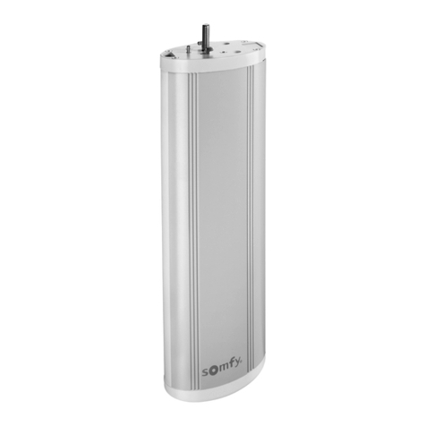
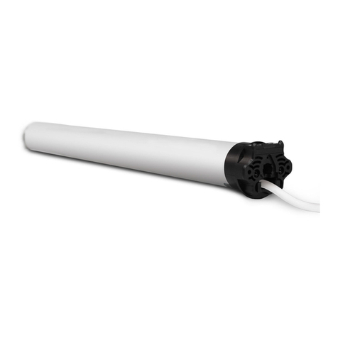
GAPOSA SileoXS XSDC30 User manual

XSDC30
EN
ULTRA QUIET MOTORIZATION

CAREFULLY FOLLOW THESE INSTRUCTIONS. IT IS VERY IMPORTANT FOR THE SAFETY
OF THE OPERATOR AND ALL OTHER CHILDREN OR BYSTANDERS. SAVE THESE INSTRUC-
TIONS. IT IS IMPORTANT TO:
• Checktheblindinmotionandkeepchildrenandbystandersfarfromitwhileinaction.
• Frequentlycheckifanylossofbalance,signsofwearordamagedwiresareshown.
• Donotuseifanyrepairingormaintenanceisneeded.
• Incaseofinstallationinawningskeepadistanceofatleast1.5ftfromit(completelyopen)andwhateverxeditemnearby.
• Thedeviceisnotintendedtobeusedbyanyone(includingchildren)whosephysical,sensoryormentalcapabili-ties
arereduced,orlackingexperienceorknowledge,unlesstheyhavebeengrantedthroughtheintermediaryofaperson
responsiblefortheirsafety,supervisionorinstructionconcerningtheuseofthedevice.
• Childrenshouldbesupervisedtoensuretheydonotplaywiththedeviceand/orwithxcontroldevices.
• Thecontroldevicesinstalledinaxedmannermustbepositionedinview.
ATTENTION
Damaged electric products and batteries should not be disposed of with normal household waste.
Make sure to drop them in special provided containers or at an authorized organiza- tion that will en-
sure they are recycled.
IMPORTANT
- The motor is shipped in sleep mode
- The motor will need to be woken up in order for it to function
- Ensure the battery is fully charged prior to installation
- Motor is not shipped fully charged, the battery comes 30% charged from the factory
Frequency bands 868,30 MHz
Duty rating 6 min
Insulation class III
Operating temperature 0°C to +60°C
Protection rate IP 20 (for indoor use only)
Motor diameter 25 mm 25 mm 25 mm 25 mm 28 mm
Motor lenght 535 mm 550 mm 350 mm 350 mm 370 mm
*WARNING: The internal regulator works up to 15VCC
2
XSDC3EX030W
XSDC3EX030B
XSDC3EX030BI
XSDC3EX030BE
XSDC3EX030BC
XSDC3EX226B
XSDC3EX226BI
XSDC3EX226BE
XSDC3EX226BC
XSDC3EX128
XSDC3DX128
XSDC3ED128
XSDC3EX228
XSDC3DX228
XSDC3ED228
Type 12VCC power
operated*
embedded
Li-Ion battery
(External battery
for BE version)
embedded
Li-Ion battery
(External battery
for BE version)
power operated power operated
Power supply 12VCC 12VDC 12VDC 24VDC 24VDC
Torque 1.1 Nm 1.1 Nm 2 Nm 1.5 Nm 2 Nm
Speed 30 rpm 30 rpm 26 rpm 28 rpm 28 rpm
Power 15 W 15 W 18 W 22 W 25 W
Amps 1.40 A
(Stand-by 300 µA) 1.40 A 1.60 A 0.90 A 1.10 A
Max turns 70 70 70 35 35


3
Ø > 25mm
B
A
L
1
3
5
7
2
4
6
8
Check that the inner diameter of the tube is
greater than 25mm.
Cut and deburr the roller tube to the required
length and remove the swarf.
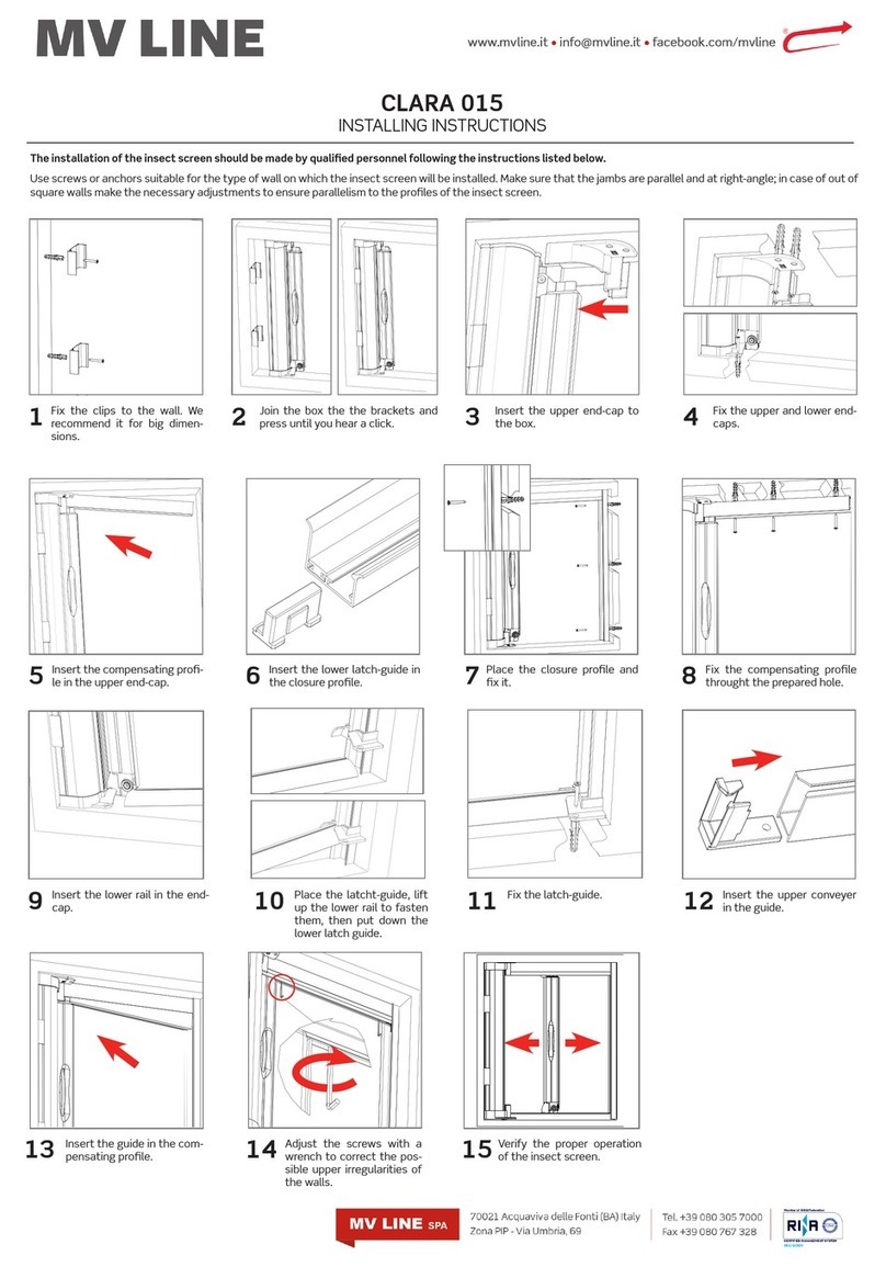
1. INSTALLATION
Insert the adaptors that will fit the roller tube:
insert the crown (A) and the motor drive wheel (B)
on the motor.
WARNING: for some of the smaller tubes, you
need to remove the stock bushing to install the
appropriate crown (A).
Measure the length (L) between the inner edge of
the motor head and the edge of the motor drive
wheel.
Screw the bracket interface on to the motor head
Slide the motor into the roller tube Slide the end cap into the roller tube and lock it if
necessary
Mount motorized tube onto brackets

4
2. WIRING - POWER SUPPLY
XS DC super quiet motors are powered by different power sources according to the type:
ATTENTION: Ensure battery is fully charged
prior to installation. IT IS NOT SHIPPED FULLY
CHARGED Battery comes 30 percent charged
from the factory. Use power charger (recom-
mended by Gaposa) to charge the integrated
Li-Ion battery.
1. Plug charger into a power outlet
2. Connect the charger to the motor power
cable
3. LED light on charger will show the status:
Solid Red = charging
Solid Green = Charging is complete
4. When charging is complete (time is about
3.5 h), disconnect and store charger for later
use
1. Plug the power supply into a power outlet
2. Plug the power suppy into the motor
CAUTION
- Ensure cable is kept clear of fabric
- Ensure antenna is kept straight and away
from metal objects
NOTES
Cables which pass through a metal wall must
be protected and isolated using a grommet or
sleeve. Attach cables with intent to prevent any
contact with moving parts. Leave the motor po-
wer supply cable accessible: it must be possible
to replace it easily.
Battery charger (cod. BC12)
Input:100-240 VAC - 50/60 Hz
Output: 12 VDC 1000 mA
Plug 3.5 x 1.35
Power supply (cod. TRASDC3)
Input:100-240 VAC - 50/60 Hz
Output: 24 VDC 2.0 A
Plug 5.5 x 2.1
Check that the mains voltage available on
the system is as shown on the label.
The motor mains connection should be
executed according to the diagram on the
next page, by qualified technicians able to
operate in compliance with the rules.
White = Com
Black = Direction of rotation 2
Orange = Direction of rotation 1
DRY CONTACT
24VDC
Positive
2XSDC3DX128
Power operated motor
XSDC3EX228
XSDC3ED228
3XSDC3DX228
Power operated motor
XSDC3EX228
XSDC3ED228
1XSDC3EX030B Li-Ion integrated battery motor
XSDC3EX226B

5
1 2 3
B
QCT..01 QCT..02 QCT..04
A
4. TRANSMITTERS
5. PROGRAMMING TRANSMITTERS
Press and hold the PROG-TX button
(on the back of transmitter or on the
head of the motor)until the motor
starts moving
Check the motor rotation then
release the PROG-TX button (the
motor stops)
Within 5 seconds, press the
corresponding button (UP if the
motor turns upwards or DOWN if
the motor turns downwards).
Transmitter is now programmed.
3. SLEEP MODE (only for Li-Ion integrated battery motor)
Sleep mode is a status which prevents a motor from moving during shipping or assembling:
Wake up the motor: click the push button on the head of the motor
the motor makes 1 jog
Activate sleeping mode: click the push button on the head of the motor
the motor makes 2 jogs
Note: any short press of the button on the head of the motor will either wake up the
motor or activate sleeping mode sequentially.
ATTENTION: In an installation of more than one XSDC battery motors wake up one
motor at a time in order to pair it to its own transmitter.
Push- button
WARNING: The internal regulator
works up to 15VCC
4XSDC3EX030W Power operated motor 12VCC
Antenna Power cable
right wire
Positive +
Black wire
UP
STOP
DOWN
PROG-TX
Set the limit switch
Program the transmitter
PROG-FC
A
B
QCT..03

6
1
1
2
2
3
6. ADDING TRANSMITTERS
7. CHECKING / CHANGING DIRECTION
Press UP or DOWN the motor should go UP or DOWN, otherwise to change the motor direction:
Press and hold the PROG-
TX button on the back of
transmitter ALREADY PAIRED
until the motor starts moving
Check the motor rotation
then release the PROG-TX
button (the motor stops)
Press and hold the PROG-TX button on the
back of transmitter until the motor starts
moving
Within 5 seconds, press the
corresponding button (UP if the
motor turns upwards or DOWN if
the motor turns downwards) on
the new transmitter that needs to
be programmed
Press STOP: The motor makes a brief jog. Direction of the
motor has been reversed.
IMPORTANT: change direction must be performed before
starting limit setting otherwise limits must be reset
1 2
4
3
5
Run the motor to an intermediate position
inbetween the two desired limits. The
motor needs to move in the direction
of the limit in order for the limit to be
properly set.
Press and hold the PROG-FC
button on the back of transmitter
until the motor makes a brief jog.
Note: during “programming
mode” the operations are in
“deadman control” (The UP and
DOWN buttons must be held
down inorder to move the motor)
Note: Accurate limit setting can be performed when UPWARD or DOWNWARD by pressing the PROG-FC button
a second time: the motor then moves slowly in steps towards to the desired limit. Always press STOP button
to set the limit position
Press and hold the
UP button and run
the motor to the
desired UP limit
position
Press and hold the
DOWN button and
run the motor to the
desired DOWN limit
position.
Press STOP to set the
UP limit position. The
motor makes a brief jog
to confirm
Press STOP to set the
UP limit position. The
motor makes a brief
jog to confirm.
8. LIMIT SWITCH SETUP ALWAYS SET THE UP LIMIT FIRST.

7
3”
9. SETTING THE LIMITS INDIVIDUALLY
If the limits need to be changed after the initial limit setting procedure, it is possible to change the limit
positions individually. One limit can be set without the other limit needing to be set. The motor can be in any
postion to initiate the procedure.
Stop the blind in the
desired intermediate
position
Press both the UP and DOWN
buttons simultaneously until
the motor makes a brief jog in
both directions.
The intermediate position has
been set.
Press and hold the STOP button
for at least 3 seconds: the shade
will move to the intermediate
position.
Press both the UP and DOWN
buttons simultaneously until
the motor makes a brief jog
in both directions.
10. SETTING THE INTERMEDIATE POSITION
11. RECALLING THE
INTERMEDIATE POSITION
12. ERASING THE
INTERMEDIATE POSITION
TO CHANGE THE UP LIMIT:
TO CHANGE THE DOWN LIMIT:
1
1
2
2
3
3
From any point between the existing limits, press
and hold both the PROG-FC button and the UP
button until the motor makes a breif jog.
Note: during “limit setting mode” the operations
are in “deadman control” (The UP and DOWN
buttons must be held DOWN inorder to move the
motor.).
From any point between the existing limits, press
and hold both the PROG-FC button and the DOWN
button until the motor makes a breif jog.
Note: during “limit setting mode” the operations
are in “deadman control” (The UP and DOWN
buttons must be held DOWN inorder to move the
motor.).
Press and hold the
UP botton until the
desired new UP limit
is reached.
Press and hold the
DOWN botton until the
desired new DOWN limit
is reached.
Press the STOP button to set
the limit. The motor makes
a brief jog to confirm. The
new up limit is set.
Press the STOP button to set
the limit. The motor makes
a brief jog to confirm. The
new up limit is set.
1 2

1
1
23
2
ON
OFF
ON
A5
GAPOSA srl - via Ete, 90 - 63900 Fermo - Italy
www.gaposa.com
13. DELETING A TRANSMITTER OR A CHANNEL
Using the transmitter to be deleted press
and hold both the PROG-TX and STOP
buttons until the motor makes a small jog.
Only the transmitter used for this procedure
has been deleted from motor memory.
14.ERASE TRANSMITTER MEMORY (DELETING ALL THE
TRANSMITTERS OR CHANNELS OR SENSORS)
Option 1 - Using a programmed transmitter
Press and hold both the PROG-TX and STOP
buttons for at least 15 seconds: to confim
that the operation has completed, the
motor first makes a brief jog and after
5 seconds it makes an additional jog.
This operation will not work unless it
makes both jogs.
Memory is now empty.
<15”
5”
1. Activate sleep mode: click the push
button (the motor makes 2 jogs)
2. Wake up the motor: click the push
button (the motor makes 1 jog)
3. Within 8 seconds, using any Gaposa
transmitter, press and hold both the
PROG-TX and STOP buttons until the
motor makes a long jog.
Memory is now empty
1. Switch the motor power supply power Off. Then
switch it ON.
2. Within 8 seconds, using any Gaposa transmitter,
press and hold both the PROG-TX and STOP
buttons until the motor makes a long jog.
Memory is now empty
for Li-Ion integrated battery motor
for power operated motor
Option 2 - Using a new transmitter without ID
(not paired).
This manual suits for next models
15
Table of contents
Other GAPOSA Window Blind manuals
Popular Window Blind manuals by other brands

SelectBlinds
SelectBlinds OPEN ROLL Z-125 installation instructions

Costway
Costway OP70275 user manual

vidaXL
vidaXL FPR-312674 Operating and safety instructions

Beme
Beme Decopolitan instructions

IKEA
IKEA PRAKTLYSING manual

Gale Pacific
Gale Pacific Coolaroo SOLAR MOTORISED 490904 Assembly & operating instructions