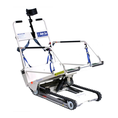
Garaventa Xpress II User manual

OWNER’S MANUAL
Xpress II Inclined Platform Lift


The Garaventa Xpress II Inclined PLatform Lift
Congratulations on the purchase of your new Xpress II inclined platform lift. This manual
describes the many features of the Xpress II, how to operate it properly and how to per-
form simple safety and maintenance checks. Please make sure that you read this Manual
before operating the lift.
The serial number will be required when discussing service issues with the local Garaventa
Lift dealer or Garaventa Lift factory technicians. Please make a note of the serial number in
this Manual. It is printed on a label afxed to the conveyance cover, behind the fold-down
seat, if so equipped. Also, please record the date on which your Xpress II was installed.
This is important for warranty reference.
Serial Number ______________
Installation Date ____________
Your Xpress II has been designed to provide years of reliable performance. However, it
will require maintenance and service. Your Garaventa dealer is knowledgeable about the
maintenance and service requirements of your lift. Please make note below for future
contact.
Authorized Garaventa Lift Dealer:
Name:
Address:
Telephone:
If you have any questions, consult your local dealer or contact Garaventa Lift by telephone
at 1 (800) 663-6556 toll-free in North America or (604) 594-0422. We are available by
email at customerrelations@garaventalift.com or you can submit an inquiry at our web-
site, www.garaventalift.com.


Table of Contents
1. SAFETY FIRST!...........................................................................................6
DO NOT TRANSPORT FREIGHT........................................................................6
DO NOT STAND ON PLATFORM........................................................................6
DO NOT PLACE HANDS BEHIND PLATFORM.......................................................6
PASSENGER MUST ALWAYS FACE DIRECTION OF TRAVEL...................................6
DO NOT OVERLOAD THE LIFT ........................................................................6
PREVENT PEDESTRIAN CONTACT WITH MOVING PLATFORM...............................6
2. COMPONENT IDENTIFICATION...................................................................7
3. BASIC OPERATING INSTRUCTIONS............................................................8
4. ADDITIONAL INSTRUCTIONS FOR OPTIONAL FEATURES............................9
FOLD-DOWN SEAT FOR AMBULATORY PASSENGERS...........................................9
EMERGENCY STOP........................................................................................9
ATTENDANT REMOTE CONTROL......................................................................9
MANUAL PLATFORM SAFETY STOP...................................................................9
5. INSTRUCTIONS FOR EMERGENCY MANUAL LOWERING..............................10
6. SCHEDULEDMAINTENANCE.......................................................................12
7. WARRANTYINFORMATION........................................................................13
WARRANTY REGISTRATION..........................................................................13
EXTENDED WARRANTY PROTECTION..............................................................13
8. SPECIFICATIONS.....................................................................14

1. Safety First
The warning symbol to the left is used throughout this Owner’s Manual to
draw your attention to procedures that must be followed to avoid possible
danger and injury.
The following procedures are very important to ensure the safe operation
of your Xpress II.
Do Not Transport Freight
The lift must never be used for anything but its intended use.
Do not use the lift to transport goods or freight.
Do Not Stand on Platform
If you are not using a wheelchair or scooter and want to use the lift, use
the optional fold-down seat for ambulatory passengers.
Never stand on the platform while it is moving. Passengers must remain
seated at all times.
Do Not Place Hands behind Platform
Do not place hands or ngers behind platform
Do not touch any moving parts.
Passenger Must Always Face Direction of Travel
For proper viewing of the stairway the passenger must always face in the
direction of travel. This is essential when traveling downward.
Do Not Overload the Lift
Rated load is 225 kgs. (495 lbs) Do not exceed this limit.
Only one passenger may ride on the platform. An attendant must walk
beside the platform and use the pendant control.`
Prevent Pedestrian Contact with Moving Platform
Use caution when operating the lift to prevent accidental contact between
stairway pedestrians and moving platform.
- 6 -

2. Component Identication
Platform Control Panel
Wrap around
safety arms
Mains power
breaker switch
Fold down seat
(optional)
Boarding ramps with
obstruction sensing
Upper rail
Lower rail
- 7 -

3. Basic Operating Instructions
Call Station
1. Check to make sure no one else is using
the lift. If the lift is already at your land-
ing, proceed to step 4.
2. If the platform is at the other station,
insert your key into the key switch and
turn to the “On” position. Press and hold
the call button.
3. Once the lift reaches your landing, re-
lease the button. To unfold the platform
press the unfold button. Remove your
key from the station and take it with you.
4. Once you have boarded the lift, lock your
wheelchair brakes. If you are using the
fold-down seat, fasten your seat belt be-
fore operating the lift.
Platform Controls
5. Insert your key in the key switch (if
equipped) located above the directional
buttons. Turn your key to the “On” po-
sition. This should illuminate the direc-
tional buttons.
6. Press and hold the appropriate direction-
al button to travel to your desired land-
ing.
7. Once you reach your desired landing, re-
lease the directional button. The wrap-
around safety arms and ramps will open
automatically to allow you to exit the
platform.
8. Turn your key to the “Off” position and
remove it before leaving the platform.
Call Station
9. Insert your key into the key switch and
turn to the “On” position. Press the fold
button to fold the platform up. Remove
your key.
10. The directional buttons may also be
used to send the platform to the other
landing.
Emergency
Stop Switch Key Switch
Platform Directional
Travel Buttons
- 8 -
Directional Controls
Platform Unfold
Platform Fold
Attendant Call
(Optional)
Key Switch
Emergency Stop
(Optional)

4. Additional Instructions for Optional Features
Fold-down Seat for Ambulatory Passengers
• To use, fold the seat down and fasten the seat belt before operating the
lift.
• When exiting the platform, tuck the seat belt back into the holder pro-
vided.
• Fold the seat back up and secure with Velcro strap.
• Caution: Ensure that the seat is folded up before attempting to fold the
platform
Emergency Stop
• An Emergency stop button is located on the platform control panel.
• The emergency stop button must be manually reset by turning the but-
ton clockwise.
Attendant Remote Control
• To use, attach the remote control to the jack located between the two
directional buttons on the platform.
Note: Once the remote control is attached, the remote control buttons
override the platform control buttons.
Manual Platform Safety Stop
• In the case of an emergency, manually lift the platform into the folded
up position. Secure the platform using the strap located on the back
of the lift. The strap has a hook or snap to be attached to the outside
of the kick plate.
- 9 -

5. Instructions for Emergency Manual Lowering
If the lift stops while occupied, the emergency hand wheel should be used
to move the platform to the desired location.
To operate the emergency manual lowering system, you may wish to refer
to the following illustrations while proceeding with these steps:
1. Turn off the mains breaker switch at the end of the upper rail (Warning:
We do not recommend that you lock the switch in the “ON” position
with a padlock when the lift is in normal use. If you do so, you must
ensure that the padlock key is accessible).
2. Locate the manual lowering hand wheel on the left hand side behind
the platform. The hand wheel must be engaged in the motor drive be-
fore it will move the lift.
3. To engage the drive hand wheel, gently push and turn the hand wheel
to the right until the lowering gears mesh (you may need to turn the
wheel slightly while pushing to fully engage the two wheels. Be careful
not to force this wheel while turning.
Refer to page 7 for Manual lowering hand wheel location.
4. By turning the hand wheel clockwise or counterclockwise, the lift will
move up and down the stairs.
Mains Breaker Switch
(at the end of the upper rail)
- 10 -

5. Instructions for Emergency Manual Lowering
5. Continue turning the hand wheel until you have moved the platform to the desired
landing. Be careful not to go past the landing position. At the top landing, the platform
will be level with the upper oor. At the bottom landing, the underside of the platform
will touch the lower oor.
6. Once the platform reaches the landing, disconnect the ramp linkages by opening the
clips at the end of the ramp operating cables. The ramp will then lower to the oor.
7. To raise the optional safety arm, push the safety arm inwards towards the hanger and
pivot it into an upright position. It will stay in the raised position once you release the
inward pressure. The passenger will then be able to exit the platform.
Drive Hand wheel
Drive Hand wheel
Drive Hand wheel
8. Manually raise the platform into an up-
right position and hold it in place using
the strap on the back of the platform. To
do this, bring the strap over the top of
the platform and clip it to the ring on the
side ramp kick plate.
Note: This strap is to be used only in the
event of an emergency!
9. Ensure the mains breaker switch is in the
‘Off’ position.
10. Phone your authorized Garaventa rep-
resentative for assistance.
- 11 -
Platform Strap
Drive Hand Wheel
Drive Hand Wheel
Drive Hand Wheel

6. Scheduled Maintenance
Regular checks and routine maintenance are essential to keep your Xpress II in proper
working order and should save you money over the long term.
It is the responsibility of the lift owner to ensure that maintenance is performed on a
regular basis. It is recommended that a thorough servicing be carried out by your au-
thorized Garaventa Lift representative every three months or twenty-ve hours of use,
whichever comes rst.
Your Garaventa Lift representative has the training, expertise and parts to keep your
Xpress II operating properly for many years. Ask your local representative about a
Scheduled Maintenance Agreement. This agreement will ensure that your lift will be
properly maintained, and that the life of your Xpress II will be extended. Depending on
the length of this agreement, your warranty could be extended up to ve years.
Remember to report any signicant problems, such as unusual noises or vibrations,
to your representative or Garaventa Lift. Do not operate the lift under these conditions.
Between your representative’s service calls, the owner can assist with the maintenance
of the lift by checking the following points:
• Ensure that the extrusions, platform and other elements of the system are kept
free of dirt, grease, wax and water.
• Contact your representative immediately if structural bolts and anchors appear to
be loose.
• Check the safety features described in this manual. For example, ensure that the
touch-sensitive ramps and plates (under the platform) stop the lift when met by
an obstruction.
• Ensure the lift is operated periodically – it should be run at least once a week.
- 12 -

8. Specications
Platform:
Platform Size: 800mm x 1250mm (31 ½” x 49 ¼”)
800mm x 1220mm (31 ½” x 48”)
800mm x 1000mm (31 ½” x 39 ⅜”)
750mm x 900mm (29 ½” x 35 ½)
Rated load: 225 kg (495 lbs), with a ve times safety factor.
Speed: Up: 4 meters (13 ft) per minute,
Down: 4.9 meters (16 ft) per minute, with a soft-start/stop transition
to / from rated speed.
Equipped with: Non-slip surfaces on the deck and ramps.
Power fold mechanism for the arms, ramps and platform.
Platform protects the conveyance control switches when in the folded
position.
Conveyance
Option: Ambulatory fold-down seat, complete with safety belt.
Operating Controls:
Constant pressure switches for direction; momentary switches for plat-
form fold and unfold, 24 VDC.
Drive System:
Motor: 0.75 H.P., 208-240 VAC, controlled by a frequency inverter and posi-
tioned within the conveyance.
Power
Transmission: Worm gear reduction to a pinion moving on a xed gear rack.
Emergency Use: A hand wheel is provided, so that the platform may be moved to the
nearest landing, in case of a power failure.
Rail System:
Main Upper Rail: Champagne anodized aluminum extrusion weighing 8lbs per foot, with
integrally mounted zinc-plated gear rack.
Lower Rail: 1.5” x 2.5” champagne anodized aluminum extrusion.
The system can accommodate slopes from 10° to 50°.
- 14 -

8. Specications
Over speed Safety:
Located on the upper carriage of the platform, containing mechanical
over speed sensor and lock, with electrical drive cut-out protection.
Finish:
Upper and Lower Rail: Champagne anodized aluminum.
Hanger: Zinc plated frame within a vacuum formed ABS cover.
Platform: Zinc plated frame with mono color powder coated surfaces and cham-
pagne anodized ramps and side kick plates.
Note: The United States ADA Accessibility Guidelines specify a mini-
mum platform size of 48 x 30 inches (1220 x 760mm), unless techni-
cally infeasible.
Specications are subject to change without notice.
- 15 -

Authorized Garaventa Lift Representative www.garaventalift.com
© Garaventa Lift. As we are
continuously improving our products,
specications outlined in this brochure
are subject to change without notice.
Printed in Canada
10485-K-OM
Table of contents
Other Garaventa Lifting System manuals
Popular Lifting System manuals by other brands

Zinko
Zinko ZABJ-12C operating instructions

HAMACO
HAMACO ML-150-45V-D12 user manual

Kelley
Kelley aFX-C user manual

Skyjack
Skyjack 3226 Maintenance & parts manual

APlusLift
APlusLift HW-10KOH-A Installation & operation manual

Phoenix Mecano
Phoenix Mecano Rose+Krieger RKPowerlift M Memory Assembly instructions

Granberg
Granberg Baselift 6300H installation instructions

Gude
Gude GHT 500 Translation of original operating instructions

ABACO MACHINES
ABACO MACHINES ALG50A Operation manual

Aqua Creek Products
Aqua Creek Products Ambassador manual

AMGO
AMGO OH-9 Installation and service manual

AMGO
AMGO HS-12 Installation and service manual