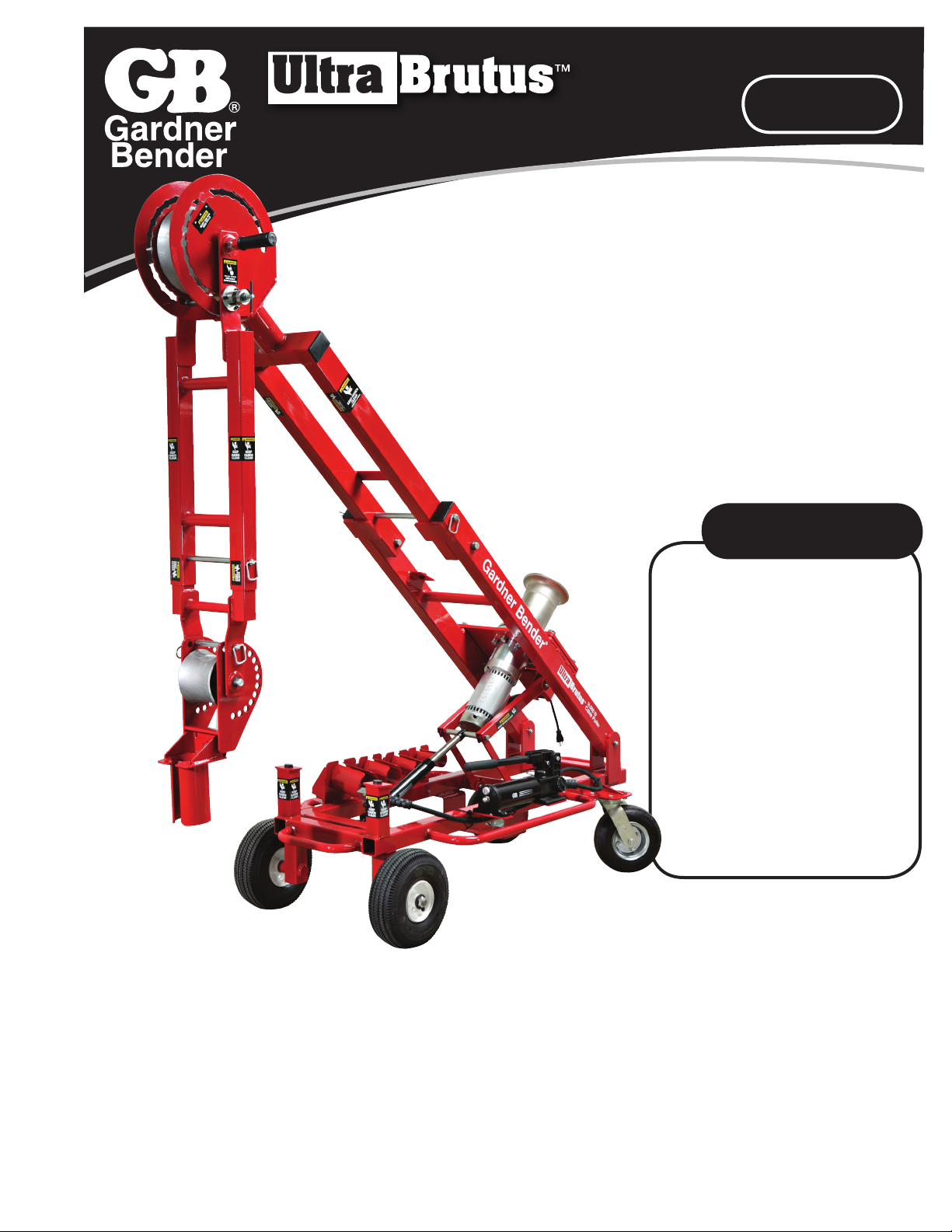
Gardner Bender Ultra Brutus CP10K User manual

1
IMPORTANT – USER SAFETY AND
PROTECTION: In setting up systems to
fit your operations, care must be taken
to select the proper components and
design to insure that all safety measures
have been taken to avoid the risk of
personal injury and property damage
from your application or system.
GARDNER BENDER is not
RESPONSIBLE FOR DAMAGE OR
INJURY CAUSED BY UNSAFE USE,
MAINTENANCE OR THE APPLICATION
OF ITS PRODUCTS. Please contact
Gardner Bender for guidance when
you are in doubt as to the proper safety
precautions to be taken in designing and
setting up your particular application.
Technical Support # 1-800-624-4320.
SAFETY ISSUES
10,000 lb. Cable Puller
Instruction Sheet
1.0 Safety Symbol Definitions . . . . . . . . . . . . . . . . . 2
2.0 Warning Labels on Product. . . . . . . . . . . . . . . . 2
3.0 Key Safety Information . . . . . . . . . . . . . . . . . . . 2
4.0 Electrical Safety Information. . . . . . . . . . . . . . . 2
5.0 Safe Pulling Guidelines . . . . . . . . . . . . . . . . . 2-3
6.0 Puller Specifications . . . . . . . . . . . . . . . . . . . . . 3
7.0 Parts Identification . . . . . . . . . . . . . . . . . . . . . . 4
8.0 Pulling Preparation . . . . . . . . . . . . . . . . . . . . . . 5
9.0 Setting Up the Machine. . . . . . . . . . . . . . . . . . . 5
9.1 Pulling Upward . . . . . . . . . . . . . . . . . . . 5-6
9.2 Pulling Downward. . . . . . . . . . . . . . . . . 6-7
9.3 Pulling Sideways. . . . . . . . . . . . . . . . . . . . 7
10.0 Rope Path General Guidelines. . . . . . . . . . . . . . . . . 7
11.0 Operating Instructions. . . . . . . . . . . . . . . . . . 7-8
12.0 Transporting the Machine . . . . . . . . . . . . . . . . . 8
13.0 Maintenance ...........................8
14.0 Additional Cable Pulling Accessories. . . . . . . . 8
CP10K

2
APPLICATION
The instruction manual and labels applied to the product provide
information for avoiding injury or death from unsafe practices
related to setting up and operating this machine. It is critical that all
personnel involved with the use of this machine understand these
hazards and unsafe practices. The three levels (Danger, Warning,
and Caution) define the severity of the hazard.
DANGER: Immediate hazards that if not avoided WILL result
in severe injury or death.
WARNING: Serious injury or death COULD occur if proper
attention is not observed.
CAUTION: Injury or property damage MAY occur if proper
attention is not observed.
The product has safety related labels securely adhered to it
in several locations. They serve to highlight the areas of this
machine that have the potential to cause injury if the operator
does not use caution. The labels include internationally
recognized symbols that are described below.
Read and understand the instruction sheet before
setting up or operating this machine.
Body parts are in danger of being crushed by
moving or moveable parts.
Body parts are in danger of being entangled in rope.
Read instruction sheet before operation.
1. Do not use the cable puller for any other purpose or
application beyond its intended use. It is intended for pulling
wire or cable through fixed conduit, with the conduit adaptor
engaged in the conduit and fastened to the cable puller.
2. Do not operate the cable puller in poorly lit areas.
3. Do not exceed the maximum rated 10,000 lbs. pulling force.
4. Inspect all cable puller components prior to operation.
5. Keep the pull rope away from the operator’s feet. Gather the
tailing rope in an area where the operator or crew cannot
become entangled.
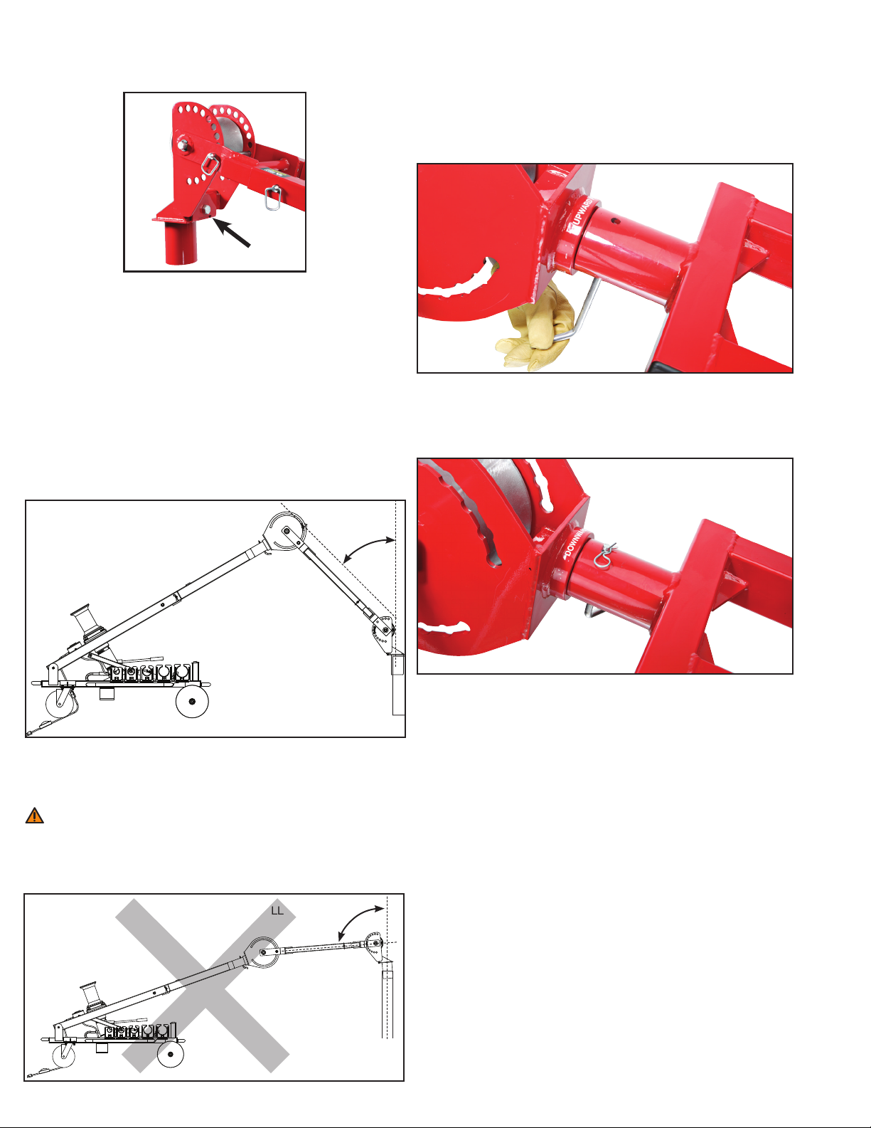
6. Never stand directly under a vertical pull or directly in line
with pull rope under tension.
7. Never use general purpose rope; always use double braided
polyester rope and inspect the rope for damage after each
pull. Do not use damaged rope for pulling cable.
8. Do not allow the rope coils to overlap on the Capstan.
9. Keep bystanders away from operations. Distractions
increase chances of injury.
10. Do not use the cable puller while under the influence of
drugs, alcohol or medication.
11. Do not operate near water or other liquids.
12. Do not wear jewelry or loose-fitting clothes. Long hair, clothing,
body parts and gloves should be clear of moving parts.
13. Always use all personal safety equipment, including eye
protection and a hard hat.
14. Do not wrap rope around legs, arms or torso of body.
15. Do not plug Power Cord directly into power source. Power
Cord must be plugged into the Footswitch.
Grounding
A three pronged grounded plug is included in the Footswitch
and must be plugged into a three hole, properly wired grounded
socket. Do not use a three prong to two prong adaptor. Never
connect the ground wire to a live terminal.
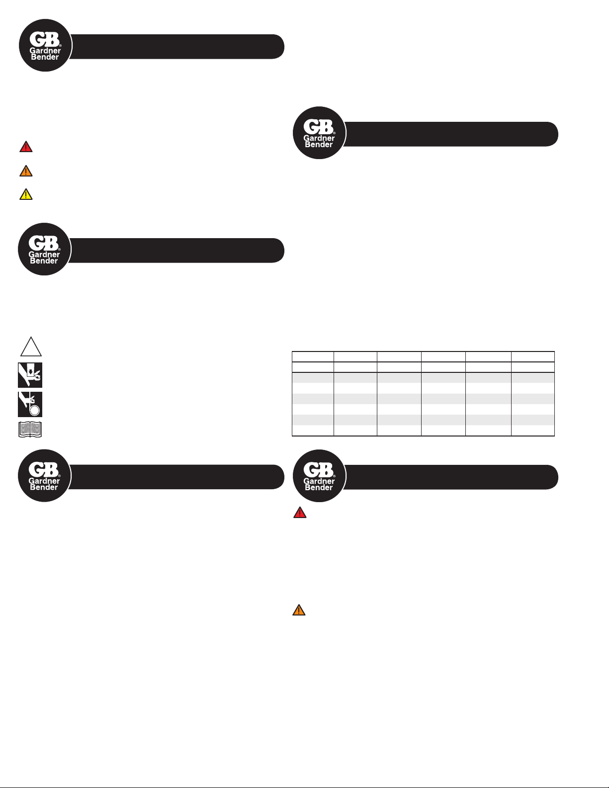
Extension Cords
1. Using an extension cord reduces the voltage supply to the
Motor. Select the appropriate wire size for extension cord
length from Table 1.
2. Only extension cords with the suffix W-A following the cord
type designation are allowed for outdoor use.
3. Extension cords must have a three prong plug and three
prong receptacles.
4. Do not use machine if extension cord has been damaged or
abused.
DANGER
1. Never expose machine to wet conditions due to electric shock.
2. Do not use or store this machine near exposed live circuits or
overhead wires.
3. Do not use a damaged or worn extension or Footswitch cord.
FAILURE TO OBSERVE THESE DANGERS WILL RESULT IN
SEVERE INJURY OR DEATH
WARNING
1. The maximum pulling capacity must not be exceeded.
2. Use the recommended size rope for pulling load. See
6.0 Puller Specifications.
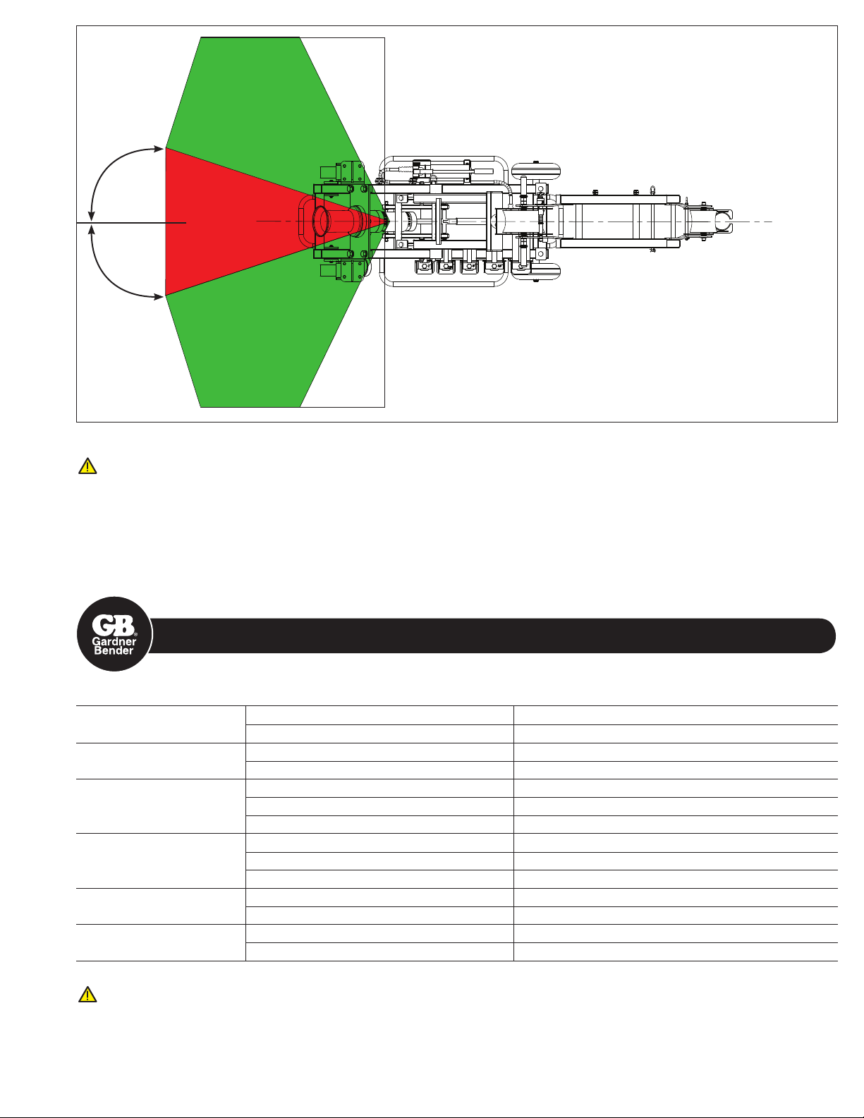
3. Rope may beak or pulling grip may come loose under tension.
Stand in the safe zone which is at least 30 degrees to either
side of rope. (See Figure 1)
4. Rope must be replaced if the strands are worn or cut.
5. Use the correct size Conduit Adaptor.
FAILURE TO OBSERVE THESE WARNINGS COULD RESULT
IN SEVERE INJURY OR DEATH
1.0 SAFETY SYMBOL DEFINITIONS
2.0 WARNING LABELS
ON PRODUCT
!
!
!
3.0 KEY SAFETY INFORMATION
Total Amps: 0-5.0 5.1-7.0 7.1-12.0 12.1-16.0 16.1-20.0
Length (ft.) Wire Gauge Wire Gauge Wire Gauge Wire Gauge Wire Gauge
25 18 18 16 14 12
50 18 16 14 12 10
75 18 14 12 10 8
100 18 12 10 8 8
150 16 12 8 8 6
200 16 10 8 6 4
4.0 ELECTRICAL SAFETY
INFORMATION
Table 1. Extension Cord Minimum Wire Gauge Guide
5.0 SAFE PULLING
GUIDELINES
!

3
CAUTION
1. Inspect machine to be free of all rust, dirt and grit.
2. Eye protection, hard hats and all personal safety equipment needs to be worn.
3. Power Cord must be plugged into Footswitch.
4. Do not allow rope to rub anywhere other than pulley rollers and Capstan.
5. Do not wear loose fitting clothes.
FAILURE TO OBSERVE THESE CAUTIONS MAY RESULT IN SEVERE INJURY OR DEATH
CAUTION
1. Inspect pulling rope. Do not use if damaged.
2. Do not allow rope to rub anywhere other than pulley rollers and Capstan.
3. Do not exceed capacity of Motor force. Observe Pull Meter for reference.
FAILURE TO OBSERVE THESE CAUTIONS MAY RESULT IN DAMAGING MACHINE MOTOR OR SEVERE INJURY
Total Amps: 0-5.0 5.1-7.0 7.1-12.0 12.1-16.0 16.1-20.0
Length (ft.) Wire Gauge Wire Gauge Wire Gauge Wire Gauge Wire Gauge
25 18 18 16 14 12
50 18 16 14 12 10
75 18 14 12 10 8
100 18 12 10 8 8
150 16 12 8 8 6
200 16 10 8 6 4
SAFE
SAFE
DANGER
Figure 1. Stand in Safe Zone
Table 2. Puller Specifications
Weight Shipping Weight 455 lbs.
Product Weight 385 lbs.
Shipping Dimensions Pallet 66" wide x 36" deep
Overall Height (includes pallet): 44"
Product Dimensions
Wheel Span 28"
Length 61"
Height 39"
Motor
Volts 115 VDC
Current 14 amps
Type 1-phase
Pulling Force Max Capacity (Intermittent Duty) 10,000 lbs.
Continuous 8,000 lbs.
Rope Green & Yellow Zone on Pull Meter 3/4" double braided polyester rope
Red Zone on Pull Meter 7/8" double braided polyester rope
6.0 PULLER SPECIFICATIONS
Looking Down from Above
30°
30°

4
7.0 PARTS IDENTIFICATION
1. Steering Handles
2. Caster Wheels & Brakes
3. Hydraulic Pump
4. Main Boom
5. Boom-A
6. Boom-B
7. Boom-A Lock Pin
8. Pulley-A Housing
9. Boom-B Lock Pin
10. Boom-B Extension
11. Boom-B Extension
Lock Pin
12. Pulley-B Housing
13. Pulley-B Housing
Lock Pin
14. Pull Orientation Pivot
15. Pull Orientation Pin
16. Conduit Adaptors
17. Power Cord
18. Footswitch
19. Pull Meter & Switch Box
20. Capstan
21. Motor
22. Pin Clips
1
8
6
10
12
15
14
21
3
18 16
9
11
13 5
4
20
19
17
2
22
7

5
If all cable diameters within the bundle are the same, select your
grip from Table 3.
If individual cable diameter is not known, or the cables within the
bundle are of different diameter, use Table 4.
WARNING
1. Inspect rope for damage prior to use. Do not use a damaged
rope. Using a damaged rope can result in a pull failure and
damage to the cables.
2. Inspect the pulling grip for damage prior to use. Do not use a
damaged pulling grip. Using a damage pulling grip can result
in a pull failure and damage to the cables.
FAILURE TO OBSERVE THESE WARNINGS COULD RESULT
IN SEVERE INJURY OR DEATH
9.1 PULLING UPWARD
1. Position the machine near the conduit box, leaving enough
room to unfold and properly adjust the boom structure.
2. Lock the brakes on the casters.
3. Close the Hydraulic Pump valve by turning clockwise. Do not
over-torque.
4. Release the pump handle lock and pump the Main Boom up
to a 30 degree angle. The Main Boom pivot bracket is marked
for 30 degrees. (See Picture 1)
5. Remove Boom-A Lock Pin and temporarily store in Pin Clips.
DANGER: Check for overhead wires prior to unfolding the
boom structure.
FAILURE TO OBSERVE THESE DANGERS WILL RESULT IN
SEVERE INJURY OR DEATH
6. With one hand on the Steering Handle and one hand on
Boom-B, lift and rotate Boom-A and Boom-B together until it
stops inline with the Main Boom. (See Picture 2)
WARNING: If you do not place your hands as instructed, then
you may crush your hand or fingers. If you do not observe the
machine warning labels, you may crush your hand or fingers.
FAILURE TO OBSERVE THESE WARNINGS COULD
RESULT IN SEVERE INJURY OR DEATH
7. Re-insert Boom-A Lock Pin and retaining clip.
!! This is extremely important !!
8. While holding on to Boom-B securely, release the Boom-B
Lock Pin. Adjust angle of Boom-B and re-engage the
Boom-B Lock Pin to secure it. Confirm the pin is fully
engaged. (See Picture 3)
9. If necessary, adjust the length of Boom-B with the Boom-B
Extension. Remove Boom-B Extension Lock Pin and slide out
the extension to one of 5 lock holes. (See Picture 4)
10. Select the correct size Conduit Adaptor, which is stored on
the machine cart frame.
Table 3. Pulling Grip Guide With Known Cable Diameter
Number of Cables in Each Grip and Diameter Range
INDIVIDUAL CABLE DIAMETERS
GRIP
DIAMETER
2 3 4 5 Range
.30 – .38 .25 – .31 .22 – .27 .19 – .24 .50 – .61
.38 – .44 .31 – .36 .27 – .31 .24 – .29 .62 – .74
.44 – .59 .36 – .49 .31 – .42 .29 – .38 .75 – .99
.59 – .75 .49 – .63 .42 – .54 .38 – .48 1.00 – 1.24
.75 – .90 .63 – .76 .54 – .65 .48 – .58 1.25 – 1.49
.90 – 1.07 .76 – .89 .65 – .77 .58 – .67 1.50 – 1.74
1.07 – 1.22 .89 – 1.02 .77 – .88 .67 – .77 1.75 – 1.99
1.22 – 1.53 1.02 – 1.28 .88 – 1.10 .77 – .96 2.00 – 2.49
1.53 – 1.83 1.28 – 1.53 1.10 – 1.32 .96 – 1.16 2.50 – 2.99
1.83 – 2.14 1.53 – 1.79 1.32 – 1.54 1.16 – 1.35 3.00 – 3.49
2.14 – 2.44 1.79 – 2.05 1.54 – 1.76 1.35 – 1.54 3.50 – 3.99
2.44 – 2.75 2.05 – 2.30 1.76 – 1.98 1.54 – 1.74 4.00 – 4.49
2.75 – 3.06 2.30 – 2.56 1.98 – 2.20 1.74 – 1.93 4.50 – 4.99
Table 4. Pulling Grip Guide With Unknown Cable Diameter
CIRCUMFERENCE RANGE
(inches)
GRIP
DIAMETER RANGE
(inches)
1.57 – 1.95 .50 – .61
1.95 – 2.36 .62 – .74
2.36 – 3.14 .75 – .99
3.14 – 3.93 1.00 – 1.24
3.93 – 4.71 1.25 – 1.49
4.71 – 5.50 1.50 – 1.74
5.50 – 6.28 1.75 – 1.99
6.28 – 7.85 2.00 – 2.49
7.85 – 9.42 2.50 – 2.99
9.42 – 11.00 3.00 – 3.49
11.00 – 12.57 3.50 – 3.99
12.57 – 14.14 4.00 – 4.49
14.14 – 15.71 4.50 – 4.99
9.0 SETTING UP THE MACHINE
8.0 PULLING PREPARATION
Picture 1 Picture 2
Picture 3 Picture 4
Measuring
Circumference
30 Degrees

6
11. Align the Conduit Adaptor hole with the Pulley-B Housing
bracket hole and tighten securely with the provided Conduit
Adaptor hex-head bolt. (See Picture 5)
12. Remove Pulley-B Housing Lock Pin.
13. Release the brakes on casters and re-position machine
reasonably perpendicular to conduit wall.
14. Make final adjustments until the Conduit Adapter is properly
inserted inside of the conduit.
•TheMainBoomanglecanbeincreasedbypumping
the Hydraulic Pump. The angle can be reduced by
slowly opening the pump valve. !! Use Caution !!
•TheangleofBoom-B,thelengthofBoom-B,andthe
Pulley-B Housing angle can be adjusted as needed.
15. Install the Pulley-B Housing Lock Pin to secure the
pulley housing.
•Ingeneral,thepullangleshouldbekeptsmallasshown
above. Try to set up the machine so that Boom-B is not at a
large angle relative to the conduit. For conduit boxes further
from the ground, this is not always possible.
WARNING: For all set-up conditions, the rope must be in
contact with both pulleys. If the rope is not in contact with both
pulleys, then the Boom structure WILL fail under load.
FAILURE TO OBSERVE THESE WARNINGS COULD RESULT
IN SEVERE INJURY OR DEATH
9.2 PULLING DOWNWARD
1. Start by following steps 1 through 8 as described in PULLING
UPWARD.
2. To set-up the machine for downward pulling, Boom-B has to
be rotated 180 degrees at the Pull Orientation Pivot (Part 14).
Do not do this by removing Boom-B extension and
re-installing it upside down.
3. Remove the Pull Orientation Pin. (See Picture 6)
4. Rotate Pulley-A Housing and Boom-B together 180 degrees.
You will see a label at the pivot joint that reads “Downward
Pulling”. This label should be on top. (See Picture 7)
5. Replace and secure the Pull Orientation Pin.
6. Remove Pulley-B Housing Lock Pin and temporarily store it in
the side clips of Boom-B. You will re-install it after engaging
the Conduit Adaptor with the conduit opening.
7. Make preliminary adjustments to position the Main Boom,
Boom-A and Boom-B for a downward pull to assure that rope
will contact both pulleys.
8. Release the brakes on the casters and re-position the
machine perpendicular to the conduit wall.
9. Make final adjustments until the Conduit Adapter is properly
inserted inside of the conduit.
•TheMainBoomanglecanbeincreasedbypumping
the Hydraulic Pump. The angle can be reduced by
slowly opening the pump valve. !! Use Caution !!
•TheangleofBoom-B,thelengthofBoom-B,andthe
Pulley-B Housing angle can be adjusted as needed.
10. Install the Pulley-B Housing Lock Pin to secure the pulley
housing.
Picture 5
Picture 6
Picture 7
SMALL PULL
ANGLE
LARGE PULL ANGLE
AVOID LARGE PULL ANGLES

7
CAUTION: There are no set-up conditions that the rope
should pass through Boom-B.
FAILURE TO OBSERVE THESE CAUTIONS MAY RESULT IN
SEVERE INJURY OR DEATH
9.3 PULLING SIDEWAYS
1. Start by following steps 1 through 8 as described in PULLING
UPWARD.
2. To set up the machine for sideways pulling, Boom-B has to be
rotated 90 degrees at the Pull Orientation Pivot (Part 14).
3. Remove the Pull Orientation Pin. (See Picture 6)
4. Rotate Pulley-A Housing and Boom-B together 90 degrees.
(See Picture 8)
5. Replace and secure the Pull Orientation Pin.
6. Remove Pulley-B Housing Lock Pin and temporarily store it in
the side clips of Boom-B. You will re-install it after engaging
the Conduit Adaptor with the conduit opening.
7. Make preliminary adjustments to position the Main Boom,
Boom-A and Boom-B for a sideways pull to assure that rope
will contact both pulleys.
8. Release the brakes on the casters and re-position the machine
perpendicular to the conduit wall.
9. Adjust Boom-B angle for sideways pulling. Use one of the 3 holes
on Pulley-A Housing shown above to minimize the load on the
boom structure.
10. Make final adjustments until the Conduit Adapter is properly
inserted inside of the conduit.
•TheMainBoomanglecanbeincreasedbypumping
the Hydraulic Pump. The angle can be reduced by
slowly opening the pump valve. !! Use Caution !!
•TheangleofBoom-B,thelengthofBoom-B,andthe
Pulley-B Housing angle can be adjusted as needed.
11. Install the Pulley-B Housing Lock Pin to secure the pulley housing.
1. A small pull angle is better than a large pull angle as it places less
stress on the cable being pulled.
2. If the rope is not contacting both rollers, then the set-up is wrong.
3. If the rope passes through Boom-B or Boom-B Extensions, then
the set-up is wrong.
4. If the rope is rubbing on the Boom-Structure or the Conduit
Adaptor, then the set-up is wrong.
5. The only time that the rope should rub a non-pulley surface is
in the set-up for a downward pull. In this case, the rope might
contact the Boom-A Lock Pin. This is okay as the lock pin has a
smooth, round outer surface.
1. Set-up the machine. READ 9.0 SETTING UP THE MACHINE.
2. Route the rope from the conduit opening, across both pulleys, to
the Capstan. READ 10.0 ROPE PATH GUIDELINES.
3. Wrap the rope around the Capstan counter-clockwise from the top.
Use 3 to 4 wraps minimum and additional wraps for heavy pulls.
Six to eight feet of rope should be free for the start of a pull.
4. Set-up the Footswitch. Plug the cord from the machine’s pull
Meter Box into the Footswitch cord receptacle. Make certain that
the switch on the meter box is set to OFF. Plug the Footswitch
plug into a 115V 3-prong grounded socket or extension cord
receptacle. READ EXTENSION CORD WIRE GAUGE GUIDE.
WARNING: DO NOT CONNECT THE MACHINE'S CORD
DIRECTLY TO A POWER SOURCE. The machine must be
activated only with the Footswitch.
FAILURE TO OBSERVE THESE WARNINGS COULD RESULT IN
SEVERE INJURY OR DEATH
Picture 8
10.0 ROPE PATH GENERAL
GUIDELINES (All Set-ups)
11.0 OPERATING INSTRUCTIONS
PULL ANGLE
Looking Down from Above
Use one of
3 holes
PULLING DOWNWARD
Ropes must contact both pulleys.
Rope should not pass through
Boom-B.

8
IMPORTANT: RECEIVING INSTRUCTIONS
Visually inspect all components for shipping damage. If you find damage, notify the carrier at once. Shipping damage is NOT covered by warranty.
The carrier is responsible for all repair or replacement costs resulting from damage in shipment.
REPAIR AND SERVICE INSTRUCTIONS: For repair service and parts contact your nearest Gardner Bender Service Center or refer to enclosed service manuals.
The Gardner Bender Service Center will provide complete and prompt service on all Gardner Bender products.
PARTS AND SERVICE: For quality workmanship and genuine Gardner Bender parts, select an Authorized GB Service Center for your repair needs.
Only repairs performed by an Authorized Service Center displaying the official GB Authorized sign are backed with full
factory warranty. Contact Gardner Bender (414)352-4160 for the name of the nearest GB Authorized Service Center.
WARRANTY: Gardner Bender warrants its product against defects in workmanship and materials for 1 year from date of delivery to user.
Warranty does not cover ordinary wear and tear, abuse, misuse, overloading, altered products or use of improper fluid.
WARRANTY RETURN PROCEDURE: When question of warranty claim arises, send the unit to the nearest GB Authorized Service Center for inspection, transportation prepaid.
Furnish evidence of purchase date. If the claim comes under the terms of our warranty the Authorized Service Center
will REPAIR OR REPLACE PARTS AFFECTED and return the unit prepaid.
5. Perform a final safety check as follows, prior to initiating
the pull.
A. Pulley-B Housing Lock Pin is secure
B. Boom-B Extension Lock Pin is secure
C. Boom-B Lock Pin is secure and completely engaged
D. Pull Orientation Pin is secure
E. Boom-A Lock Pin is secure
F. Conduit Adaptor Bolt is secure
G. The Footswitch has been positioned in the safe-pull
zone (See Figure 1)
H. The operator is not wearing any loose clothing
I. There is no one standing in line with the rope
6. Turn on the switch at the Meter & Switch Box.
7. Activate the Capstan rotation by stepping on the Footswitch.
8. Gradually apply tension to the rope to begin the pull.
WARNING: Immediately remove foot from Footswitch if
Boom Structure becomes unsteady or if pulling rope becomes
entangled.
FAILURE TO OBSERVE THIS WARNING COULD RESULT IN
SEVERE INJURY OR DEATH
1. Remove the Conduit Adaptor prior to collapsing.
2. Restore the machine to its folded, collapsed position.
3. Unlock the brakes on the casters prior to moving the machine.
WARNING: Collapsing the machine improperly can be
extremely unsafe if not done properly. There are numerous
opportunities to severely injury your fingers and hands. The
machine is equipped with numerous warning labels to help highlight
the potential pinch points. However, not all pinch points are labeled.
Never use gripping locations near a potential pinch point.
FAILURE TO OBSERVE THESE WARNINGS COULD RESULT
IN SEVERE INJURY OR DEATH
•Inspectandcleanallsurfacesbeforeeachoperation.
•CheckforPowerCordandFootswitchCorddamage.Replace
if damaged.
•Replaceanycomponentsthatarenotfunctioningproperly.
•Occasionallylubricatecasterpivots(zinctting).
•Occasionallylubricatecasteraxles(zinctting).
•Occasionallylubricate10"Wheelaxles(zinctting).
•CheckandrelltheHydraulicPumpoilwithEnerpacPNLX101
if needed.
•Checkforhydraulicuidleaks.
•Touchupanypaintscratchestopreventoxidationofmetal
structure. Oxidation can weaken the steel structure and result
in failure under load.
•Checkandadjusttirepressure(4places).
•OccasionallylubricateBoom-BExtension.
•Replacepins&retentionclipsifmissing. (!! CRITICAL !!)
12.0 TRANSPORTING
THE MACHINE
13.0 MAINTENANCE
14.0 ADDITIONAL CABLE
PULLING ACCESSORIES
8,000 lb. Puller
2,000 lb. Puller
Pulling Grips
Blo-Vac
Wire Carts
Fish Tapes
Line Carriers
Hook Sheaves
Pulling Rope
Pulling
Lubricant
CO2
5 CHECK PINS
This manual suits for next models
1
Table of contents
Other Gardner Bender Industrial Equipment manuals
Popular Industrial Equipment manuals by other brands

Rego-fix
Rego-fix powRgrip PGU 9500 operating manual

CHART
CHART UltraDoser 150S product manual

ETC
ETC M-138 Operation and maintenance manual

Axi
Axi MTC HC-50 Installation, operating and maintenance manual

PushCorp
PushCorp AFD310 manual

environmental potentials
environmental potentials EP-2820 Installation and application manual