Gardner Bender Slug Out KOMD1 User manual

1
502-2 & 503-2 instructions
instruction manual
Slug Out™ Knockout Driver
KOMD1 / KOM540A / KOM520A
gardnerbender.com
IMPORTANT: SHIPPING DAMAGE
Visually inspect all components for shipping damage.
If any shipping damage is found, notify carrier at once.
Shipping damage is NOT covered by warranty. The carrier
is responsible for all repair or replacement costs resulting
from damage in shipment.
CAUTION
Read and understand instruction sheet. FAILURE TO DO
SO MAY RESULT IN SEVERE INJURY.
DESCRIPTION OF OPERATION
The Mechanical Driver is a torque multiplying device
powered by an electrical driver drill. It is intended to be
used with the Slug Out™ punches, dies, and draw studs
to punch holes in electrical panels. Round punches are
available from 1/2" to 4" (12.7mm to 101.4mm).
IDENTIFICATION
1. Handle
2. 3/4" draw stud receiver
3. 3/8" draw stud receiver
4. Square drive bit receiver
5. Punches
6. Dies
7. 3/4" draw stud
8. 3/8" draw stud
9. Square drive bit
10. Step drill bit
1.
2.
5. 6.
3.
10.9.
8.7. 4.

Slug Out™ Knockout Driver instruction manual
2
Table of Contents
Description................................................... 1
Identification ................................................ 2
Safety Issues ............................................... 2
Drilling Guide Holes..................................... 3
Punching 1/2" Holes .................................... 3
Punching 3/4"-3" Holes................................ 3
Punching 3-1/2"-4" Holes ............................ 4
Repair and Service Instructions .................. 4
Parts and Service ........................................ 4
Warranty ...................................................... 4
Warranty Return Procedure......................... 4
CAPACITY
• Use only cordless minimum 14.4V drill to power mechanical driver
• Mechanical driver is designed for 10 GA steel max.
Damage can occur if used on higher gauge steel.
• When punching holes in 10 GA steel, use low speed setting on drill.
• Hole Capacity: 1/2"–4"
• Also can use impact driver

Slug Out™ Knockout Driver instruction manual
3
SAFETY SYMBOL DEFINATIONS
The instruction manual and labels applied to the product provide information for
avoiding injury or death from unsafe practices related to setting up and operating
this machine. It is critical that all personnel involved with the use of this machine
understand these hazards and unsafe practices. The three levels (Danger, Warning,
and Caution) define the severity of the hazard.
DANGER: Immediate hazards that if not avoided WILL result in severe
injury or death.
WARNING: Serious injury or death COULD occur if proper attention is
not observed.
CAUTION: Injury or property damage MAY occur if proper attention is
not observed.
KEY SAFETY INFORMATION
• Do not use the mechanical knockout driver for any other or application beyond its
intended use. It is intended for making holes in light guage steel.
• Do no operate the mechanical knockout driver in poorly lit areas.
• Do not attempt to exceed stated capacity.
• Do not operate while standing on a ladder or any elevated platform that has not
been proven to be stable and guarded to prevent falls.
• Keep bystanders away from operations. Distractions increase chances of injury.
• Do not operate the mechanical knockout driver as a team. The opterator alone
should grip the knockout driver handle and the driver drill.
• Do not operate the mechanical knockout driver while under the influence of drugs,
alcohol or medication.
• If using a corded driver drill, do not operate near water or other liquids.
WARNING: Failure to read, understand and adhere to the key safety information
could result in severe injury or death.

Slug Out™ Knockout Driver instruction manual
4
SETUP AND OPERATION
DRILLING GUIDE HOLE
1. Mark the center position; drill a 1/8" pilot hole.
2. If working to close conduit clearences, mark the center position by scribling cross
lines shown in figure 1.
3. When assembling the punch to the pull rod, align the cross marks with the four
marks on the outer die surface.
NOTE: If pre-punched knockouts are already in the desired location, drilling a guide
hole is not required.
4. Enlarge the 1/8" pilot hole with a 7/16" drill bit or the step drill bit.
PUNCHING 1/2" HOLES
1. Attach the square drive bit to driver drill chuck.
2. Thread the 3/8" draw stud into the mechanical knockout driver's 3/8" draw stud
receiver. (fig. 2 )
3. Slide the 1/2" die over the draw stud, flat side toward the mechanical knockout driver.
4. Insert draw stud through guide hole.
5. Thread the 1/2" punch to the draw stud. (fig. 3)
6. Make sure all punch cutter points are tight to the panel.
7. Insert square drive bit into the square drive bit receiver (fig. 4)
CAUTION: Use one hand to firmly grip the knockout driver handle and use the
other hand to firmly grip the driver drill. Brace yourself for a torque reaction. Failure
to observe this caution may result in injury or lossing your balance and falling.
8. Holding the mechanical knockout driver in position, keep pulling the trigger until
punch completely penetrates the metal.
9. Remove the punch set from the hole. Reverse the driver drill until draw stud is
exposed. Remove punch form draw stud. Slide the die off the draw stud. To
remove the slug, turn over and tap lightly on a solid wooden object.
Drilling of Guide Hole
Figure 1

Slug Out™ Knockout Driver instruction manual
5
Figure 2
Figure 4
Figure 3
Punch
Die

Slug Out™ Knockout Driver instruction manual
6
PUNCHING 3/4" TO 3" HOLES
1. Follow instructions for drilling guide hole and punching a 1/2" hole. DO NOT DRILL
A 1/2" HOLE.
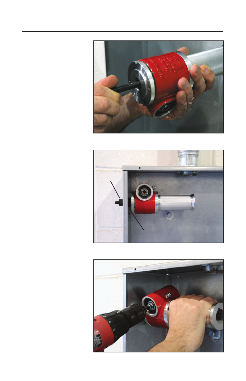
2. Drive mechanical knockout driver till the 3/4" draw stud receiver is slightly exposed.
3. Thread the 3/4" draw stud into the mechanical knockout driver's 3/4" draw stud
receiver till it bottoms out. (fig. 5).
4. Select the punch and die set needed (3/4"–3"). Slide the die over the pull rod, flat
side toward the mechanical knockout driver.
5. Place 3/4" draw stud into the guide hole.
6. Thread the punch onto the 3/4" draw stud.
7. Insert square drive bit into the square drive bit receiver (fig. 6)
CAUTION: Use one hand to firmly grip the knockout driver handle and use the
other hand to firmly grip the driver drill. Brace yourself for a torque reaction. Failure
to observe this caution may result in injury or lossing your balance and falling.
8. Holding the mechanical driver in position, keep drill driving until punch completely
penetrates the metal.
9. Remove the punch set from the hole. Reverse the driver drill until draw stud is
exposed. Remove punch form draw stud. Slide the die off the draw stud. To
remove the slug, turn over and tap lightly on a solid wooden object.
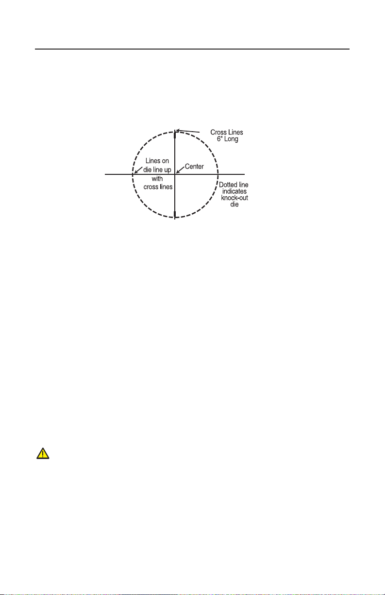
NOTE: To avoid excessive wear and tear on the draw stud threads during punching,
center the pull rod accurately so that it does not rest against the metal edge of the
guide hole. Also, be sure that all points of the punch are in uniform contact with the
metal surface when starting to punch.
PUNCHING 3-1/2" AND 4" HOLES
1. Larger punch sizes require a 1-15/16" diameter guide hole (use 1-1/2" punch and
die) and a KC3540 converter.
2. Follow all the instructions for drilling guide hole (page 4). Punch a 1/2" hole per
instructions on page 4. Punch a 1-1/2" hole per instructions above.
3. Remove the 1-1/2" punch and die. Install the 3-1/2" or 4" die over the draw stud. (fig. 7)
4. Install the KC3540 converter on the inside of the punch. (fig. 7)
CAUTION: Do not install the converter (KC3540) on outside of punch. Damage to
the draw stud would result from incorrect converter installation.
5. Place the draw stud into the guide hole. Thread the punch on the draw stud and
turn until the converter is into the guide hole.
6. Place 3/4" draw stud into the guide hole.
7. Thread the punch onto the 3/4" draw stud.
8. Insert square drive bit into the square drive bit receiver (fig. 6)
CAUTION: Use one hand to firmly grip the knockout driver handle and use the
other hand to firmly grip the driver drill. Brace yourself for a torque reaction. Failure
to observe this caution may result in injury or lossing your balance and falling.

Slug Out™ Knockout Driver instruction manual
7
Figure 6
Figure 5
Figure 7
• Punch

Slug Out™ Knockout Driver instruction manual
8
ADDITIONAL HELP
• We recommend an 18 volt cordless drill or larger, or an impact driver.
• The life of the mechanical knockout driver will be sigificantly extended if you
occasionally remove the draw stud receiver (toward the handle exit) and brush it
with a heavy grease.
• If grease leaks from the gear housing, then occasionally add grease (2 oz) through
the zerk fitting.
• To prevent thread damage, be sure punch is threaded onto the stud until the stud
extends beyond the punch.
• Hand tighten punch and die prior to engaging driver drill.
REPAIR AND SERVICE INSTRUCTIONS
For repair service and parts contact your nearest Gardner Bender® Service Center.
The Service Center will provide complete and prompt service on all Gardner Bender®
products.
PARTS AND SERVICE
For quality workmanship and genuine Actuant®parts, select an Authorized Actuant®
Service Center for your repair needs. Only repairs performed by an Authorized
Service Center displaying the official Actuant®Authorized sign are backed with full
factory warranty. Contact Actuant 800-624-4320 for the name of the nearest Actuant®
Authorized Service Center.
WARRANTY
Gardner Bender®warrants its products against defects in workmanship and materials
for 1 year from date of delivery to user. Chain is not warranted. Warranty does not
cover ordinary wear and tear, abuse, misuse, overloading, altered products or use of
improper fluid.
WARRANTY RETURN PROCEDURE
When question of warranty claim arises, send the unit to the nearest Actuant®
Authorized Service Center for inspection, transportation prepaid. Furnish evidence
of purchase date. If the claim comes under the terms of our warranty the
Authorized Service Center will REPAIR OR REPLACE PARTS AFFECTED and
return the unit prepaid.
PO Box 3241 • Milwaukee, WI 53201-3241
800.624.4320 • fax: 800.799.3779 • gardnerbender.com GAR_TL_019_0511
This manual suits for next models
2
Table of contents