Note: T he follo wing procedure assumes boom
lift switc hes are installed on the mac hine . F or
mac hines without boom lift switc hes or if y ou
ha v e not already installed the switc hes from the
Electric Boom Lift Kit, install those switc hes no w
as described in the instr uctions with that kit. Do
not install the wire har ness than comes with the
Electric Boom Lift Kit.
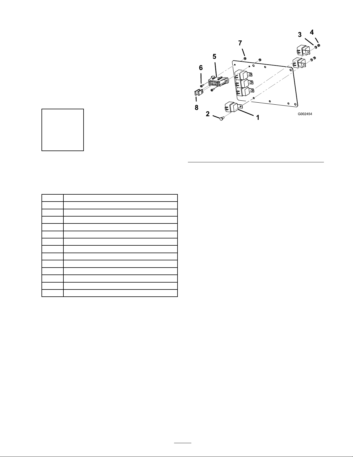
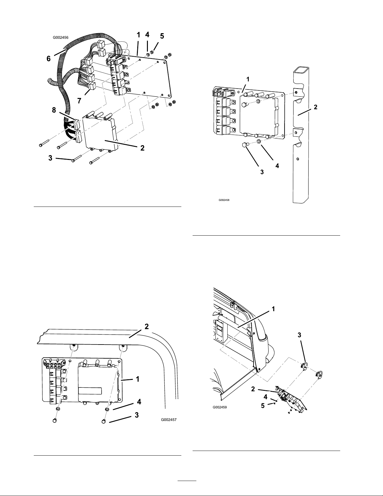
1. R emo v e the spra y control panel to expose the
bottom side ( Figure 13 for the 1250 and Figure
14 for the 1200).
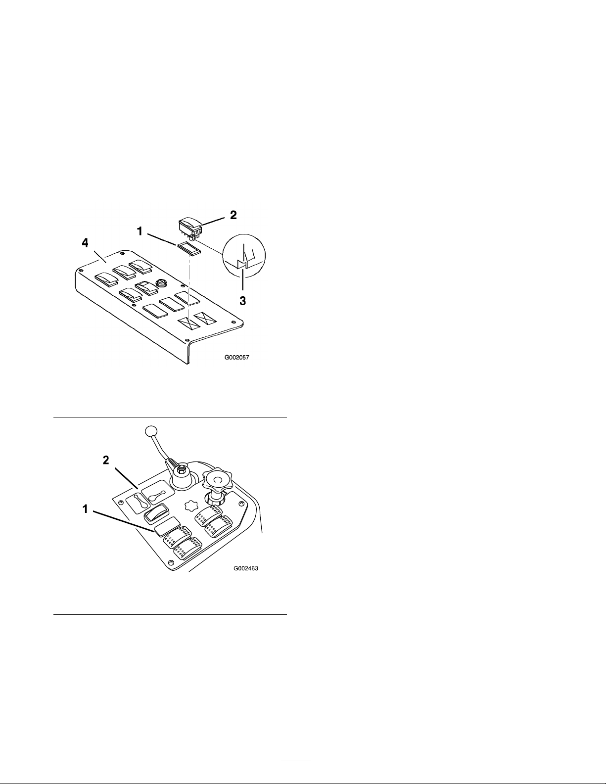
Figure 13
1. Plug
3. Notch (at back)2. Switch 4. Spray control panel
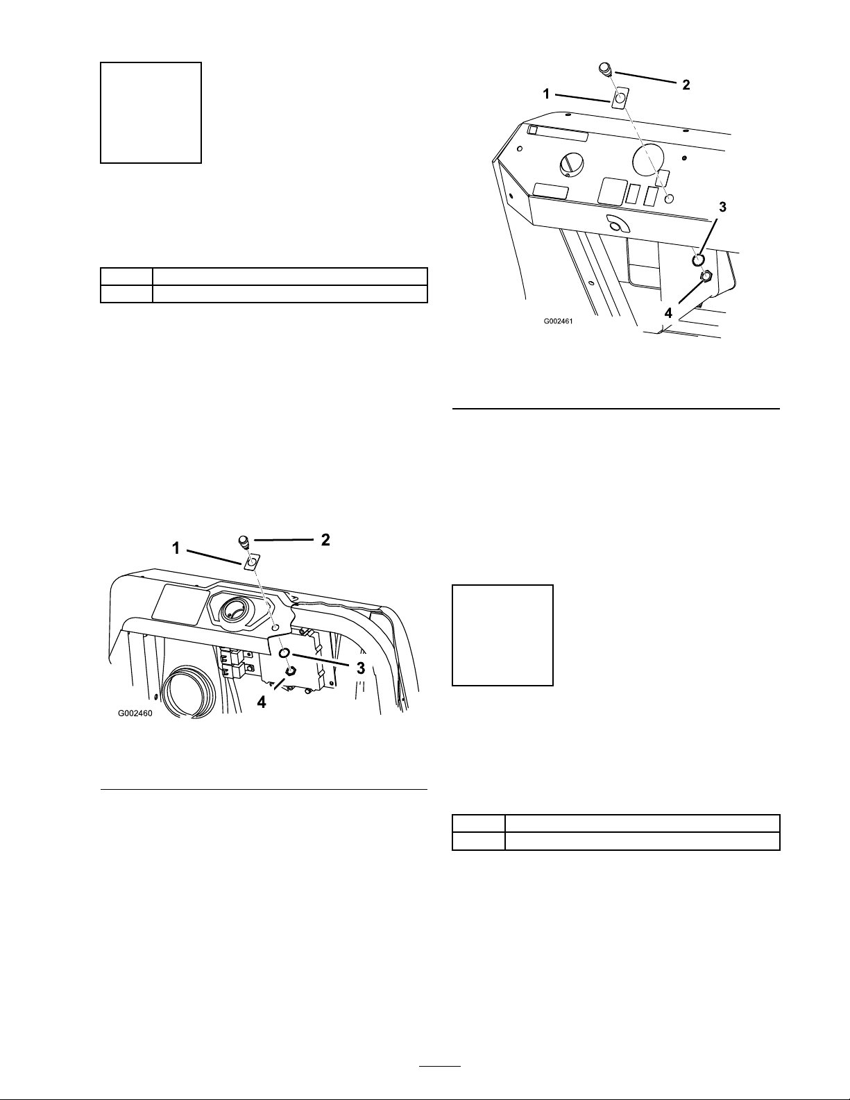
Figure 14
1. Sonic boom switch location 2. Spray control panel
2. R emo v e the plug in the sonic boom slot from
the spra y control panel on the v ehicle and
install the roc k er switc h pro vided in its place
( Figure 13 for the 1250 and Figure 14 for the
1200).
Note: Ensure that the orientation of the
switc h matc hes what is sho wn in Figure 13 ,
with the notc h pointing to w ard the rear of the
v ehicle .
W iring the Switches
1. R oute the branc h of the sonic boom wire
har ness with the three larg e connectors into
the control panel area.
2. If boom lift switc hes are installed remo v e
any existing connectors plug g ed into the lift
switc hes .
3. Connect the connector with g reen and white ,
g reen and blac k, and blac k wires to the bottom
of the right boom lift switc h.
4. Connect the connector with blue and white ,
blue and blac k, and blac k wires to the bottom
of the left boom lift switc h.
5. Connect the connector with pur ple , yello w ,
and blac k wires to the bottom of the sonic
boom switc h.
6. R oute the free end of the wiring har ness do wn
through the floor and rearw ard, follo wing the
spra y system wire har ness to the center boom
assembly at the bac k of the v ehicle . Use cable
ties to secure the wiring har ness to the other
wiring har nesses a w a y from the engine and
mo ving par ts .
7. Install the spra y control panel and secure it
with the fasteners remo v ed previously .
Connecting the W iring to the Fuse Block
1. R oute the branc h of the sonic boom wiring
har ness with the small spade connector and a
ring or fork ter minal into the seat bo x and to
the fuse area.
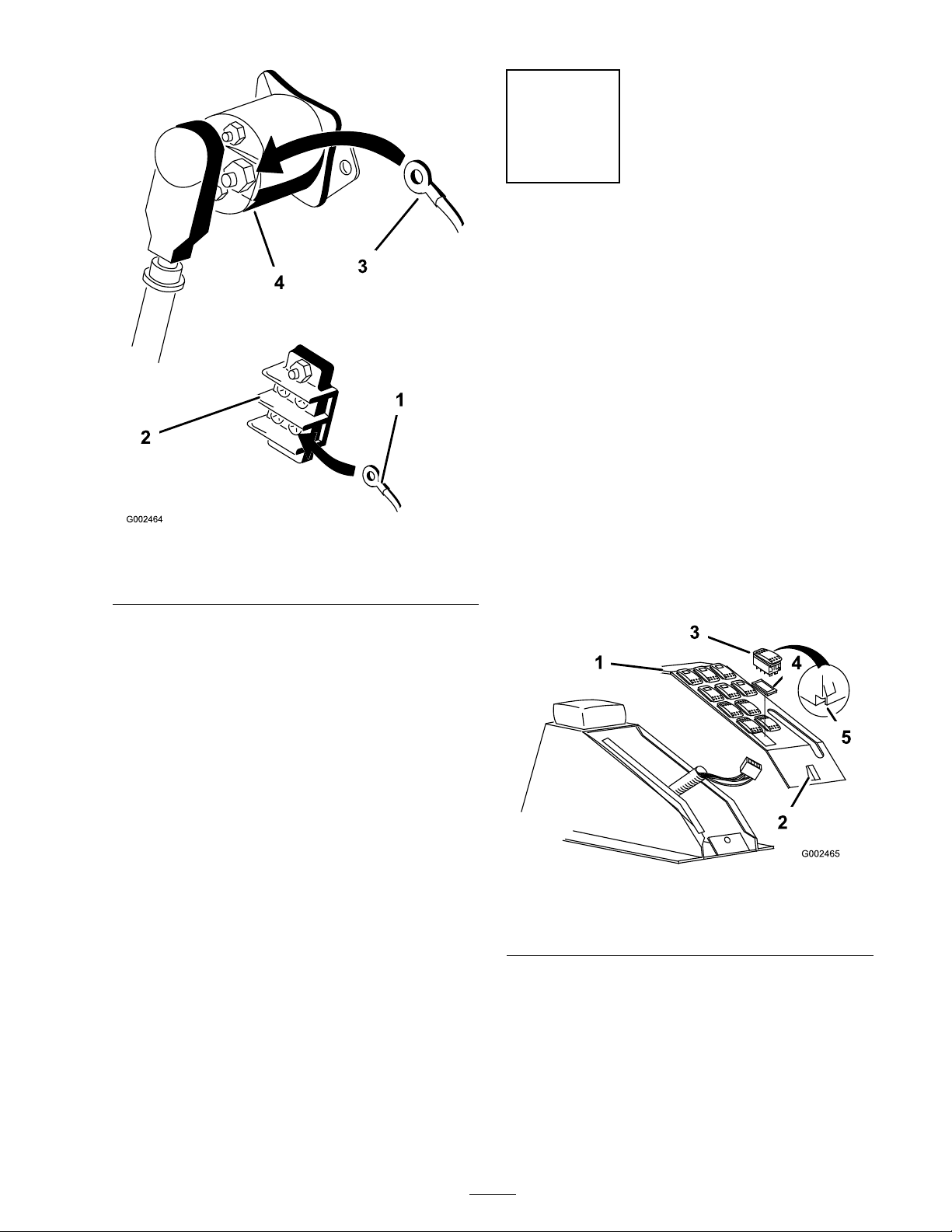
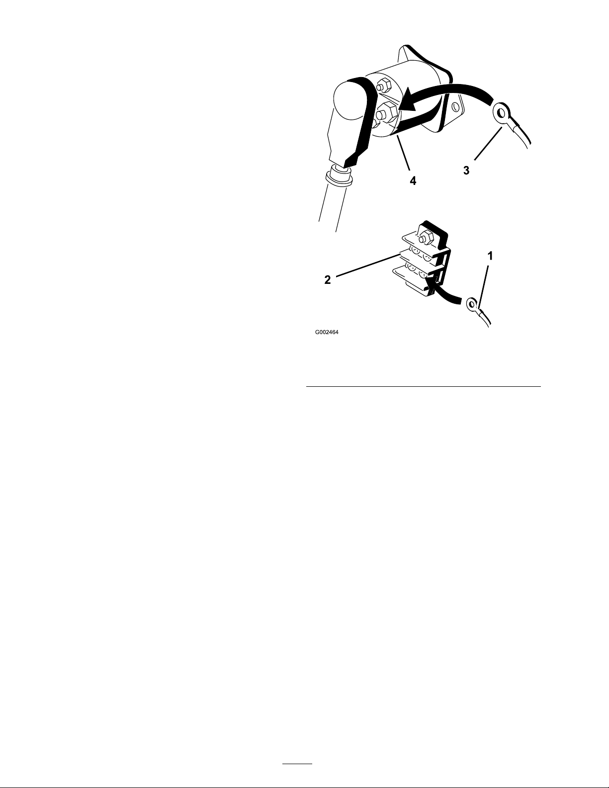
2. Lift the seat to access the fuse area. Locate the
auxiliar y solenoid and g round ter minal bloc k.
3. Connect the ring labeled g round on the blac k
wire to the g round ter minal bloc k ( Figure 15 ).
8