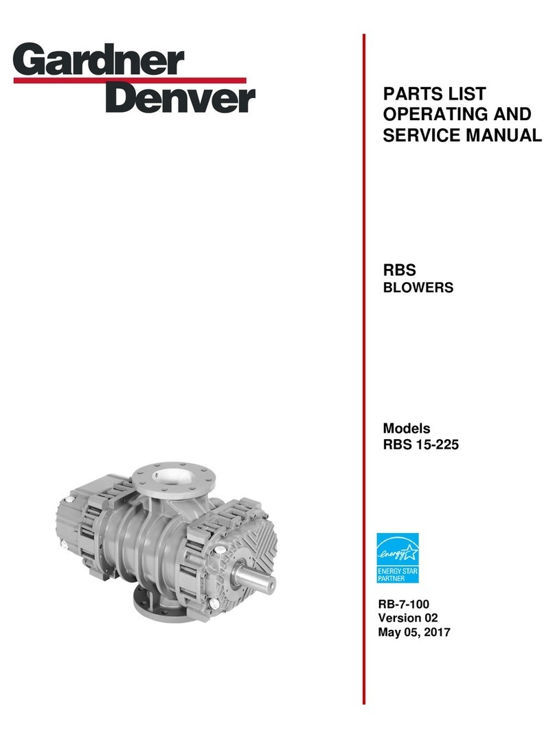
Gardner Denver RBS 15 Troubleshooting guide

SERVICE MANUAL
AND PARTS LIST
RBS
BLOWERS
Models
RBS 15-225
RB-7-100
Version 01
May 09, 2016

MAINTAIN BLOWER RELIABILITY AND PERFORMANCE
WITH GENUINE GARDNER DENVER
PARTS AND SUPPORT SERVICES
Factory genuine parts, manufactured to design tolerances, are developed for optimum dependability - - -
specifically for your blower. Design and material innovations are born from years of experience with hundreds of
different blower applications. When you specify factory genuine parts you are assured of receiving parts that
incorporate the most current design advancements manufactured in our state-of-the-art blower factory under
exacting qualitystandards.
Your AUTHORIZED DISTRIBUTOR offers all the backup you require. A worldwide network of authorized
distributors provides the finest product support in the blower industry.
1.
Trained technical representatives to assist you in selecting the correct replacement parts.
2.
Complete inventory of new machines and new, genuine factory parts.
3.
A full line of factorytested AEON® PD blower lubricants, specifically formulated for optimum
performance in all blowers.
4.
Authorized distributor service technicians are factory-trained and skilled in blower maintenance and
repair. They are ready to respond and assist you byproviding fast, expert maintenance and repair
service.
INSTRUCTIONS FORDETERMINING BLOWER CONFIGURATION
1.
Face the blower drive shaft.
2.
In a VERTICAL configuration, air flow is Horizontal.
3.
In a HORIZONTAL configuration, air flow is Vertical.
4.
In a vertical configuration, a BOTTOM HAND exists when the drive shaft is below the horizontal
center line of the blower. A TOP HAND exists when the drive shaft is above the horizontal center line
of the blower.
5.
In a horizontal configuration, a RIGHT HAND exists when the drive shaft is to the right of the vertical
center line of the blower. A LEFT HAND exists when the drive shaft is to the left of the vertical center
line of the blower.
INSTRUCTIONS FOR ORDERING REPAIR PARTS
For pricing, and ordering information contact your nearest AUTHORIZED FACTORY DISTRIBUTOR. When
ordering parts, specify Blower MODEL and SERIAL NUMBER (see nameplate on unit).
Rely upon the knowledge and experience of your AUTHORIZED DISTRIBUTOR and let them assist you in
making the proper parts selection for your blower.
To Contact Gardner Denver or locate your local distributor:
Visit: www.contactgd.com/mobile
Or
Call: (217)222-5400

GARDNER DENVER LUBRICANT ORDER
INFORMATION
Re-order Part Numbers for Factory
Recommended Lubricants.
Gear and Drive End
AEON PD Synthetic Lubricant, AEON PD-XP—Extreme Duty
Synthetic Lubricant or AEON PD-FG—Food Grade Synthetic
Lubricant
AEON PD Synthetic Lubricant
Description
Part Number
1 Quart
28G23
Case/12Quarts
28G24
1 Gallon Container
28G40
Case/6Gallons
28G41
5 Gallon Pail
28G25
55 Gallon Drum
28G28
AEON PD-XD –Extreme Duty Synthetic Lubricant
Description
Part Number
1 Quart
28G46
Case/12Quarts
28G47
1 Gallon Container
28G42
Case/6Gallons
28G43
5 Gallon Pail
28G44
55 Gallon Drum
28G45
AEON PD-FG –Food Grade Synthetic Lubricant
Description
Part Number
1 Quart
28H97
Case/12Quarts
28H98
1 Gallon Container
28H333
Case/6Gallons
28H334
5 Gallon Pail
28H99
55 Gallon Drum
28H100
Drive End
AEON PD Grease
Description
Part Number
Case/10 Tubes (14oz/Tube)
28H283

FOREWORD
RBS blowers are the result of advanced engineering and skilled manufacturing. To be assured of receiving
maximum service from this machine, the owner must exercise care in its operation and maintenance. This
m a n u a l
is written to give the operator and maintenance department essential information for day-to-day
operation,
maintenance and adjustment. Careful adherence to these instructions will result in economical
operation and
minimum downtime.
NOTICE
Notice is used to notify people of installation, operation or maintenance information which is
important but not hazard-related.
Caution is used to indicate the presence of a hazard which will or can cause minor personal injury or
property damage if the warning is ignored.
Warning is used to indicate the presence of a hazard which can cause severe personal injury, death,
or substantial property damage if the warning is ignored.
Danger is used to indicate the presence of a hazard which will cause severe personal injury, death, or
substantial property damage if the warning is ignored.

SAFETYPRECAUTIONS
Safety is everybody’s business and is based on
your use of good common sense. All situations or
circumstances cannot always be predicted and
covered by established rules. Therefore, use your
past experience, watch out for safety hazards and
be cautious. Some general safety precautions are
given below:
Failure to observe these notices could result in damage to equipment.
Stop the unit if any repairs or adjustments on or around the blower are required.
Disconnect the blower from its power source, tag and lockout before working on the
unit –this machine maybe automatically controlled and may start at any time.
Do not exceed the rated maximum speed shown on the nameplate.
Do not operate unit if safety devices are not operating properly. Check periodically.
Never bypass safety devices.
Failure to observe these notices could result in injury to or death of personnel.
Keep fingers and clothing away from revolving fan, drive coupling, etc.
Do not use the air discharge from this unit for breathing –not suitable for human
consumption.
Do not loosen or remove the oil filler plug, drain plugs, covers or break any
connections, etc., in the blower air or oil system until the unit is shut down and the air
pressure has been relieved.
Electrical shock can and may be fatal.
Blower unit must be grounded in accordance with the National Electrical Code. A
ground jumper equal to the size of the equipment ground conductor must be used to
connect the blower motor base to the unit base.
Open main disconnect switch, tag and lockout before working on the control.
Disconnect the blower from its power source, tag and lockout before working on the
unit –this machine may be automatically controlled and may start at any time.

DRIVEINSTALLATION
When selecting a V-belt drive, check to be sure the
shaft overhung load limitation is not exceeded.
Refer to
FIGURE 2-2, for overhung load calculations and
limitations.
Belt drives must be carefully aligned. Motor and
blower pulleys must be parallel to each other and
in the same
plane within 1/32 inch. Belt tension
should be carefully adjusted to the belt
manufacturer’s recommendation using
a belt
tension gauge. Check tension frequently during
the first day of operation.
.
Over tightening belts leads to heavy bearing loads and premature failure.
NOTICE
When changing mounting configuration, it may be necessary to reposition breather/oil fill (B), oil
level gauge (H) and drain plug (A). Refer to Figure 3-1, for correct location.

ENGLISH
INDEX
1
OPERATING PROBLEMS..........................................................................................
2
REMOVAL OF THE BLOWER FROM THE PLANT.....................................................
2.1
Stopping the blower.............................................................................................
2.2
Disassembling the connections...........................................................................
2.2.1
Disassembling the piping.................................................................................
2.2.2
Disassembling the silencers............................................................................
2.3
Removal of the blower from the unit ...................................................................
2.3.1
Direct coupling.................................................................................................
2.3.2
V-belt drive coupling........................................................................................
2.4
Disassembling of the driving devices..................................................................
2.4.1
Direct coupling.................................................................................................
2.4.2
V-belt drive coupling........................................................................................
3
DISASSEMBLING OF THE BLOWER .......................................................................
3.1
Preparation..........................................................................................................
3.2
Disassembling of the drive side ..........................................................................
3.2.1
Sizes from 15 to 106........................................................................................
3.2.2
Sizes from 115 to 225......................................................................................
3.3
Disassembling of the gears side.........................................................................
3.3.1
Disassembling the gear side, sizes from 15 to 25...........................................
3.3.2
Disassembling the gear side, sizes from 35 to 225.........................................
3.3.3
Extraction of the cover 5B, sizes from 15 to 25...............................................
3.3.4
Extraction of the cover 5B, sizes from 35 to 225.............................................
3.4
Final disassembling.............................................................................................
3.4.1
Cover 5A..........................................................................................................
3.4.2
Cover 5B..........................................................................................................
4
REPAIR OF THE PARTS............................................................................................
4.1
Rotors..................................................................................................................
4.2
Casing..................................................................................................................
4.3
Covers .................................................................................................................
4.4
Gear.....................................................................................................................
4.5
Bearings ..............................................................................................................
4.6
Labyrinth seals.....................................................................................................
4.7
Drive shaft seal....................................................................................................
5
ASSEMBLING OF THE BLOWER .............................................................................
5.1
Preparation..........................................................................................................
5.2
Assembling of the drive side...............................................................................
5.2.1
Sizes from 15 to 25..........................................................................................
5.2.2
Sizes from 35 to 106........................................................................................
5.2.3
Sizes from 115 to 155......................................................................................
5.2.4
Sizes from 165 to 225......................................................................................
5.3
Assembling of the gear side................................................................................
5.3.1
Sizes from 15 to 25..........................................................................................
5.3.2
Sizes from 35 to 126........................................................................................
5.3.3
Sizes from 135 to 225......................................................................................
5.4
Assembling of the labyrinth seals........................................................................
5.5
Assembling of the bearings.................................................................................
5.5.1
Bearing pos. 31 ...............................................................................................
5.5.2
Bearing pos. 32 ...............................................................................................
5.5.3
Bearing pos. 33 ...............................................................................................
5.6
Assembling of the timing gear.............................................................................
5.6.1
Preparation......................................................................................................
5.6.2
Sizes from 15 to 25..........................................................................................
5.6.3
Sizes from 35 to 225........................................................................................
5.7
Final checks........................................................................................................

ENGLISH
INDEX
6
INSTALLATION OF THE BLOWER ON THE PLANT..............................................
6.1
Assembling of the driving devices...................................................................
6.1.1
Direct drive coupling ....................................................................................
6.1.2
V-belt drive coupling ....................................................................................
6.2
Coupling the blower .............................................................................................
6.2.1
Direct drive coupling ....................................................................................
6.2.2
V-belt drive coupling ....................................................................................
6.3
Assembling of the piping .................................................................................
6.4
Putting into operation.......................................................................................
7
Technical Table .....................................................................................................
7.1
Mass of the main components ........................................................................
7.2
Bearings................................................................................................................
7.3
Tighteningtorques...........................................................................................
7.3.1
Screws and nuts ..........................................................................................
7.3.2
Plugs and sight glasses...............................................................................
7.4
Clearances............................................................................................................
7.5
Special tools....................................................................................................
7.6
References for gear tightening........................................................................
7.7
Table for tolerances check ..............................................................................
8
Blower Size ..................................................................................................................
8.1 RBS 15 - 25......................................................................................................
8.2 RBS 35 - 106......................................................................................................
8.3 RBS 115 - 126......................................................................................................
8.4 RBS 135 - 155......................................................................................................
8.5 RBS 165 - 225......................................................................................................

1 OPERATING PROBLEMS
PROBLEM
CAUSE
High absorbed power
WARNING : STOP THE BLOWER IMMEDIATELY
1-3-6-7-8-9-10-11-12-13-14
Differential pressure higher than the contract value
WARNING : STOP THE BLOWER IMMEDIATELY
1-3-6-7-8
Discharge temperature T2 higher than the contract value
WARNING : STOP THE BLOWER IMMEDIATELY
2-4-5-6-7-8
High vibrations and/or noises
WARNING : STOP THE BLOWER IMMEDIATELY
9-10-11-12-13-14-15
Oil dark
2-4-5-6-7-8-13-14-15-17-19-20-21-22
Oil leakages
15-16-17-20-21
Cooling liquid leakages
22
Shaft rotation locked or limited
9-10-11-12-13-14-15
Cracks on external surface
9-10-11-12-13-14-15
Alteration of the color of the external paint
2-4-5-6-7-8-9-10-11
Rif.
CAUSE
SOLUTION
1
Pressure
P2-P1 higher than the contract value
Reset the rated value
2
Ratio
P2/P1 higher than the contract value
3
Speed
n
higher than the contract value
4
Speed
n
lower than the contract value
5
Temperature T1 higher than the contract value
6
Filter clogged
Replace the filter element
7
Suction pipe clogged
Remove the obstruction and check the piping
8
Discharge pipe clogged
9
Scale deposits in the compression chamber
Clean the compression chamber and the rotors,
balance the rotors if necessary
10
Rotors making contact
Check the surface of the rotors, of the casing
and of the covers
Replace the parts with damaged surface
11
Intake of foreign particles
Remove the foreign particles
Clean the compression chamber
Check the clearances
12
Transmission not aligned
Check and correct the alignment
13
Bearingdamaged
Replace the bearings
14
Geardamaged
Replace the gears
15
Labyrinth seals damaged
Replace the labyrinth seals
16
Drive seal shaft damaged
Replace the shaft seal
17
Oil level too high
Reset the rated value
18
Oil viscosity too low
Change the oil type
19
Oil viscosity too high
20
Gaskets damaged
Replace the gaskets
21
Oil level plugs are broken
Replace the oil level plugs
22
Cooling circuit damaged (only/RV)
Restore the circuit
NOTE
P1 = Suction absolute pressure T1 = Suction temperature
P2 = Discharge absolute pressure T2 = Discharge temperature
n = Rotational speed

2 REMOVAL OF THE BLOWER FROM THE PLANT
2.1 Stopping the blower
If the blower is still in operation remove, if possible, the differential pressure.
Stop the electric supply
WARNING: Check that the deceleration of the blower is even and without vibrations.
Close the cooling water circuit (only for /RV)
Insulate the blower from the plant and restore the atmospheric pressure into it.
WARNING: The gas contained in the plant may be hot, toxic or irritant.
WARNING: Disconnect the electric supply, lock the general switching in open position with the
key and conserve it during service operation
WARNING: Wait until the blower returns at the ambient temperature (<40°C)
2.2 Disassembling the connections
2.2.1 Disassembling the pipes
Unscrew the screws fixing the elastic connections between the silencers and the main pipes.
Remove the elastic connections using suitable hoisting devices.
WARNING: The elastic connections with DN higher than 200 weight more than 30 kg.
If necessary disassemble also the pipe near the silencers.
NOTE: For the blower with vertical nozzles (/V) operate only on the piping connected to the
upper silencer.
In case of blowers with oil cooling circuit (/R-V) disconnect also the cooling liquid supply pipes
2.2.2 Disassembling the silencers
Unscrew the screws fixing the silencers to the blower nozzles and to their supports if any
remove the silencers using suitable hoisting devices.
WARNING: The silencers with DN higher than 150 weight more than 50 kg.
NOTE: For the blower with vertical nozzles (/V) operate only on the piping connected to the
upper silencer.

2.3 Removal of the blower from the unit
Disassemble the drive protection device
Unscrew the screws fixing the blower to the base frame
2.3.1 Direct drive coupling
Lift the blower using hoisting devices suitable to his weight (table 7.1)
Fig. 1
2.3.2 V-belt drive coupling
Loosen the V-belts approaching the motor to the blower using the screws of the motor rails
Thrust screws
Fig. 2
Remove the V-belts
Lift the blower using hoisting devices suitable to his weight (table 7.1)

2.4 Disassembling of the drive devices
2.4.1 Direct drive coupling
Loose the safetyscrew G fixing the key 30
Extract the coupling bymeans of a suitable device.
WARNING: Do not use the hammer to extract the coupling.
Screw G
Key pos. 30
Fig. 3
Remove the key 30 from blower shaft
2.4.2 V-belt drive coupling
Unscrew the fixing screws V and screws 1 or 2 of these one (following the sleeve type) alternatively into the
extraction holes E until to unlocking the sleeve, remove the pulley and the sleeve
WARNING: Do not use the hammer to extract the pulley.
E V E V
V
Fig. 4
V V E
E
TAPER LOCK system MGT system
Remove the key 30 from the blower shaft
Bronze pad

3 DISASSEMBLING OF THE BLOWER
3.1 Preparation
Clean the external surface of the blower
Drain the lubricating oil
WARNING: Dispose the used oil in accordance with local regulations
Drain the cooling liquid (onlyfor the /R-V version)
WARNING: Dispose the cooling liquid in accordance with local regulations.
Mark the position of the covers 5A and 5B and the position of the drive shaft in order to use these marks
during the following assemblyof the blower.
Put the blower onto a wooden support plane suitable to the weight of the blower as indicated in fig. 5 and
make sure that there is enough space to operate on the drive side and on to gear side.
For this operation use hoisting bands that pass around the blower casing as indicated in fig. 5, for the weight
of the blower see table 7.1.
WARNING: Use the hoisting devices suitable to the weight of the blower (table 7.1).
WARNING: Make sure that the blower is stable onto the support plane.
Fig. 5
> 1500 mm
> 1500 mm

3.2 Disassembling of the drive side
Remove the drive sump 12A
WARNING: Use the hoisting devices suitable to the weight of sump (table 7.1)
3.2.1 Sizes from 15 to 106
Extract the protection ring 37 bymeans of an extraction device as indicated in figure
Unscrew the screw 27B and extract the locking disk 17 of the bearing 32
Bronze pad
Shaft sleeve 37
Screw 27B
Locking disk 17
Fig. 6
Extract the cover 5A screwing alternativelytwo fixing screws into the suitable extraction holes
Fixing screw Fixing screw
Fig. 7

3.2.2 Sizes from 115 to 225
Unscrew the nut 27A and with it extract the shaft sleeve 37, if the operation is difficult extract the sleeve 37 by
means of an extractor device as indicated at paragraph 3.2.1
Unscrew the screw or nut 27B and extract the disk 17 locking the bearing 32
extract the oil splash disk 24
For the sizes from 115 to 126 extract the cover 5A screwing alternatively four fixing screws into the suitable
extraction holes as indicated in Fig. 7
For the sizes from 135 to 225 fix two extractor devices to the threaded holes H indicated in Fig. 8
Hole H
Fig. 8
Hole H
Extract the cover 5A operating alternativelyonto two extractor devices.
Drive extractor device
Driver extractor device
Bronze pad
Fig. 9
Size
Hole H
135-145-155
M 24
165-175
M 30
205-225
M 30

3.3 Disassembling of the gear side
Remove the gear sump 5B
WARNING: Use the hoisting devices suitable to the weight of sump (table 7.1)
WARNING : Secure the cover 5B fixing it to the casing 1 using two fixing screws pos. 90 with
big diameter washer for sizes from 15 to 126 and the prefixing screws for sizes from 135 to 225
3.3.1 Disassembling the gear side, sizes from 15 to 25
Unscrew the locking nuts 26 and remove the washers 311
Extract the wheels 11A and 11B and if necessary using an extractor device and mark their position
Bronze pad
Nut 26 Washer 311
Wheel 11A Wheel 11B
Safetyscrew
Washer
Fig. 10
During this operation also the adjusting shims 22A are removed, mark their position for the following
assemblyof the blower.
Adjusting shims pos. 22A
Fig. 11

3.3.2 Disassembling the gear side, sizes from 35 to 225
Unscrew slightly the locking nuts 26 and move them 1 or 2 mm awayfrom the gear wheels
WARNING: DO NOT REMOVE THE LOCKING NUTS 26, because by releasing the gear wheels
they may be cast out.
Screw the injector or oil pump to the end of the shaft using the suitable nipples, for the devices see table 7.5,
for the connections size see table 7.6.
Oil injector
Nut 26 Nut 26
Wheel 11B Wheel 11A
1 –2 mm
Safetyscrew
Spacer 22 Washer
Fig. 12
Inject oil until the gear wheel is released.
WARNING: The pressure of the oil during disassembly may reach 2000 bar and the incorrect
assembly of the injector or pump may cause serious physical damage owing to the jets of oil
underpressure.
Remove the injector or the oil pump and the locking nuts 26
Extract the gear wheels 11A and 11B and mark their position
WARNING: Use the hoisting devices suitable to the weight of gear wheel (table 7.1), starting
from size 165 the wheels have threaded holes to facilitate their hoisting
Extract the spacers 22 and the adjusting shims and mark their position for following assembly of the blower

3.3.3 Extraction of cover 5B, sizes from 15 to 25
Disassemble the bearing cover 35
Extract the rotors using an extractor fixed to the threaded holes of the casing as indicated in figure13
Remove the safety screws fixing the cover 5B to the casing1 and extract it
Bronze pad
Safetyscrew
Washer
Fig. 13
3.3.4 Extraction of cover 5B, sizes from 35 to 225
Disassemble the bearing covers position 35 and, for the sizes from 35 to 126, mark the position of adjusting
washer 304 for the following assemblyof the blower
Extract the rotors using an extractor fixed to the threaded holes of the bearing covers, for the sizes from 35 to
126 or to the extraction holes indicated in fig. 8 for sizes from 135 to 225
Bronze pad
Safetyscrew
Washer
Fig. 14
Fix the cover to a suitable hoisting device for the mass of the cover (table 7.1)
Remove the safetyscrews fixing the cover 5B to the casing 1 and extract it

3.4 Final disassembly
Mark the position of the rotors
Extract the rotors from the casing 1 fixing them to the threaded holes on their drive side
WARNING: For the lifting of the rotors do not use the threaded end on the gear side nor the
threaded holes on the gear side
WARNING: Use the hoisting devices suitable to the weight of the rotors (table 7.1)
3.4.1 Cover 5A
For the sizes from 35 to 106 remove the screw Pos. 407 fixing the bearing pos. 31
Extract the bearings pos. 31 and Pos. 32 from the cover 5A, if necessary use an extractor device
WARNING: Use the hoisting devices suitable to the weight of the bearings (table 7.1)
For the sizes from 35 to 225 extract the spacer’s Pos. 25 with the oil splash disks 23A and 23C
WARNING: During this operation do not damage the spacers 25 and the oil splash disks 23A
and 23C.
WARNING: Do not remove the reference pins
3.4.2 Cover 5B
Extract the bearings pos. 33 from the cover 5B, if necessary use an extractor device, mark their position and
the side towards the gear wheel
WARNING: Use the hoisting devices suitable to the weight of the bearings (table 7.1)
For the sizes from 35 to 126 extract the compensation springs Pos. 68 and mark their position
for the sizes from 135 to 225 extract the adjusting rings Pos. 67 and mark their position.
For the sizes from 35 to 225 extract the spacer’s Pos. 25 with the oil splash disks Pos. 23B and mark
their
position.
WARNING: During this operation do not damage the spacers 25 and the oil
splash disks
23B
WARNING: Do not remove the reference pins

4 REPAIR OF THE PARTS
4.1 Rotors
Clean the external surface of the rotors, remove the incrustations and rust using solvents and scraper.
WARNING: Keep to the prescribed safety rules when using solvents and wear protection
glasses and safety gloves
NOTE: Do not damage the external surface of the rotors when using the scraper
Check the external surface of the rotors, if there are any signs of seizure, cracks or grooves replace the
rotors.
Measure the external diameter DR of the rotors, the maximum thickness SL of the lobes in various
points
along their length and the maximum lengthLR of the rotors
Fig. 15
Place the rotors between the centers of a lathe as indicated in figure
Check the surface of the bearing seats on the shaft and the surface of the tapered seats of the gear wheels,
if
there are any signs of seizure, cracks or grooves also of small dimensions replace the rotors.
WARNING: Any discontinuity also of small dimensions on the external surface of the shaft
compromise the blower safety
Measure with a comparator the concentricity of the external diameter of the rotors with the seats of the
bearings as indicated in figure
Fig. 16
Communicate the values of the recorded data to ROBUSCHI to check the possibility of using the rotors again.
NOTE: In case of replacement of a rotor it is necessary always to replace both rotors
Other manuals for RBS 15
1
This manual suits for next models
23
Table of contents
Other Gardner Denver Blower manuals

Gardner Denver
Gardner Denver LEGEND GAF P Series Service manual

Gardner Denver
Gardner Denver 8000 Series Service manual

Gardner Denver
Gardner Denver HELIFLOW HYCL BA Service manual

Gardner Denver
Gardner Denver LEGEND P Series Service manual

Gardner Denver
Gardner Denver RBS 15 Service manual

Gardner Denver
Gardner Denver Industrial Series Service manual

Gardner Denver
Gardner Denver 4500 Series Service manual

Gardner Denver
Gardner Denver DuroFlow 45 Series Service manual

Gardner Denver
Gardner Denver Sutorbilt Legend P Series Service manual