Garlando TOORX BRX-9500 User manual

Ed : Rev : Cod:
INSTRUCTION
09/20 GRLDTOORXBRX950000
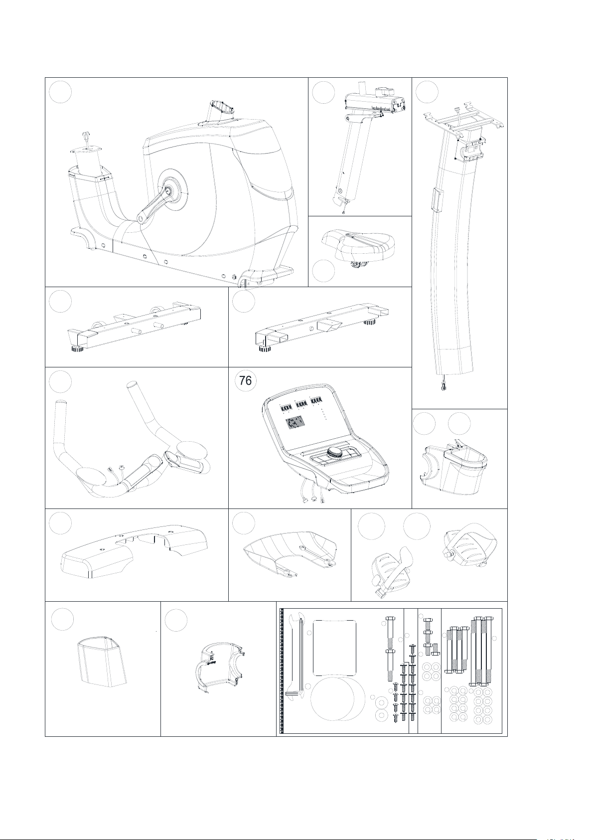
Exploded drawing:
48R
3 2
2926222421
50
48L
51L
49
46
416 78586 87
78
14
17
1
84 83 82
47 51R
27 30
56 38
11
28
76
99
3
45
6
45
12
10L 10R
71L 71R
75
9
8816
9
7A
16 79
39
36
37L 37R35L 35R
3433
25
23
43
38
42
31
79 77
52 55
53
5 5
63 64 65 3973 38
9
16
15
418
7A
32L 32R
44
68 74
39
54
101
59 61 60
38
57
58
88
TAICO
62
13
89
90
91 92
93 28
67 95 96
20 19 72 69 18 94
98
97
103
100
102
40 39
38
104105
106
107

Check list:
1
X1
51L & 51R
13 17
2
4
X1X1
X1
5
36
X1
X1
40
X1X1
75
X1
X1
X1
69
X1
X1
104 & 105
106
X1
7 M8*1.25*70L 4PCS 9 D15.4*D8.2*2T 8PCS
(mm)
STEP 1
KH-734S2
16 D16*D8.5*1.2T 8PCS
7A M8*1.25*110L 4PCS
STEP 3
15 M8*1.25*15L 4PCS 16 D16*D8.5*1.2T 4PCS 9 D15.4*D8.2*2T 4PCS
STEP 4
39 M5*12L 6PCS
STEP 5
41 M8*1.25*50L 2PCS
8 D22*1.5T 2PCS
42 97.2*75*42 1PC
38 ST4.2*15L 4PCS
39 M5*12L 8PCS
107 ST4.2*15L 4PCS

Part list:
Part no
Description
Specification
Qty
1
Main frame
1
2
Rear stabilizer
1
3
Adjustable wheel
4
4
Front stabilizer
1
5
Front stabilizer cover
2
6
Allen bolt
M8*1.25*40L
2
7
Hex bolt
M8*1.25*70L
4
7A
Hex bolt
M8*1.25*110L
4
8
Curved washer
D22xD8.5x1.5T
2
9
Spring washer
D15.4xD8.2x2T
12
10L
Front decorative cover(left)
1
10R
Front decorative cover(right)
1
11
Upper decorative cover
1
12
Rear cover
1
13
Seat post
1
14
Inner tube
50*100*340L
2
15
Allen bolt
M8*1.25*15L
4
16
Flat washer
D16*D8.5*1.2T
12
17
Handlebar post
1
18
Adjustable handle
1
19
End cap (1)
2
20
End cap (2)
2
21
bearing
#6004-2RS(C0) ,SKF
2
22
waved washer
D27*D20.3*0.5T
1
23
Screw
M3*0.5*30L
4
24
C ring
D22.5*D18.5*1.2T
2
25
cross screw
M3*0.5*12L
2
26
crank axle
1
27
pulley wheel
1
28
anti-loose nut
M6*1.0*6T
5
29
Hex bolt
M6x1.0x15L
4
30
Multi-groove belt
1
31
Round Magnet
1
32L
Upper cable for quick button(2)
400L
1
32R
Upper cable for quick button(1)
400L
1
33
Upper cover for handpulse
2
34
Lower cover for handpulse
2
35L
Membrane button (-)
1
35R
Membrane button (+)
1

36
Handlebar
1
37L
Lower cable for quick button(2)
850L
1
37R
Lower cable for quick button(1)
850L
1
38
Screw
ST4.2*15L
38
39
cross bolt
M5*0.8*12L
16
40
Back cover for console
337.6*225.5*58.4
1
41
Bolt
M8*1.25*50L
2
42
rear protective cover for
handlebar
1
43
front protective cover for
handlebar
1
44
Flat Washer
D26*D21*1.5T
1
45
crank cover
2
46
left chain cover
1
47
right chain cover
1
48L
left crank
1
48R
right crank
1
49
anti-loosing nut
M10*1.25*9T
2
50
Bolt cover
2
51L&51R
Pedal
1
52
Screw
M6*1.0*15L
4
53
spring washer
D10.5*D6.1*1.3T
4
54
Flat Washer
D13*D6.5*1.0T
4
55
Self-generator
1
56
Pin
D6*26.5*7.7
12
57
Connecting cable
500L
1
58
Connecting cable(2)
1000L
1
59
Battary connecting cable
750L
1
60
Buffer
25*2T*80
2
61
Chargeable battery
1
62
Fixing plate(1)
1
63
Upper computer cable
300L
1
64
Middle computer cable
1000L
1
65
Lower computer cable
1350L
1
67
Tension cable
D1.5*507.5L
1
68
control board
1
69
Saddle
1
71L
left gasket for chaincover
1
71R
Right gasket for chaincover
1
72
Adjustable tube for saddle
1
73
sensor cable
500L
1
74
Electric cable
700L
1

75
Upper protective cover
1
76
computer
1
77
C ring
S-17(1T)
1
78
waved washer
D17*D22*0.3T
3
79
bearing
6203-2RS , SKF
2
82
Flat washer
D28*D8.5*3T
1
83
Plastic cover
2
84
Spring
D2.2*D14*55L
1
85
Fixing plate for idle wheel
1
86
Plastic washer
D10*D24*0.4T
2
87
Nut
M8*1.25*6T
1
88
Nylon nut
M8*1.25*8T
3
89
Adjustable pole
1
90
Allen bolt
M8*1.25*16L
2
91
spring
D1.5*D14*50L
1
92
Bolt
M5*0.8*40L
1
93
Fixing bar
1
94
Tighten gasket
1
95
screw
M6*1.0*45L
1
96
Pull handle
1
97
End cap for adjustable handle
1
98
bolt
M8x1.25x50L
1
99
buffer
D10.5*20L
2
100
block plate
1
101
moving wheel
2
102
Round head cross screw
M5x0.8x10L
4
103
Inner hex fastening screw
M5*0.8*12L
2
104
water bottle holder
1
105
water bottle holder(front)(black)
1
106
water bottle holder(rear)(black)
1
107
cap
2
Allen spanner
1
open spanner
1

Assembly drawing:
STEP 1
Step-1
x4
x8
x8
7
9
16
13
15
x4
7A
4 7 916
7A
4 7 916
7A
1-2
2
916 7A
1
12
916 7A
1-4
1-3
1-1
1. Throw away the tube and bolts under the front side of the main frame into trash can as per fig
1-1. Please note they are just the parts to support the main frame to simplify your assembly.
2. Raise up the frame, assemble the front stabilizer (4) onto the main frame (1) by using the cross
bolt (7&7A), the spring washer (9) and the flat washer (16). Please refer to 1-2.
3. Throw away the tube and bolts under the rear side of the main frame into trash can as per fig
1-3. Please note they are just the parts to support the main frame to simplify your assembly.
4. Raise up the frame, assemble the rear stabilizer (2) onto the main frame (1) by using the cross
bolt (7&7A), the spring washer (9) and the flat washer (16). Please refer to 1-4.

STEP 2
Step-2
UP
DOWN
2-3
2-4
1
13
13
2-1
2-2
13
15
1. Assemble the saddle onto the saddle post by spanner. Please refer to 2-1 & 2-2
2. Adjust the saddle position vertically. Please refer to 2-3
3. Adjust the saddle position horizontally. Please refer to 2-4

STEP 3
Step-3
1
3-1
75
17
64
65
9
15
16
75
17
65
64
3-2
x4
x4
x4
15
9
16
13
15
1) Suggest assembling this step by two persons.
2) First, lift up the upper protective cover (75) like fig. (3-1), then connect the console cable (64 &
65) like fig.(3-2)
3) Insert the front post (17) on the main frame and tighten it by the flat washer (16), the spring
washer (9),and bolt (15).Place down the upper protective cover and make it tight on the main
frame.

STEP 4
Step-4
64
76
76
64
39
1
76
4-1
4-2
76
17
39
17
76
4-3
4-4
1739
40
40
x8
39
39
1) Connect the console (76) with middle cable for console (64). See fig 4-1.
2) Through the console cable into the front post (17) out. See fig 4-2.
3) Tighten the console onto front post by bolt (39). See fig 4-3
4) Fix the back cover for console (40) with console by cross bolt (39). See fig 4-4.

STEP 5
Step-5
841
36
17
76
37L
76 76
37R
R
48R
51R
51R
51L 48L
51L
48L 1
39
5
39
5
x6
39
x2
41
x28
13
15
42
66
5-1
5-2
5-3
17
105
38
107
106
1. Connect the console (76) with Lower cable for quick button(2)(37L) and Lower cable for quick
button(1)(37R).
2, Assemble the handlebar (36) onto front post (17) by the curved washer (8) and hex bolt (41).
Cover the rear protective cover for handlebar (42) .
3,Assemble the pedal (51L & 51R) with left crank (48L & 48R). Left pedal by counter-clockwise,
right pedal by clockwise.
4. Cover the cover of front & rear stabilizer (5),fasten them by using the cross bolt (39).
5.Assemble the water bottle holder(front)(black) (105) & cap (107) & the water bottle
holder(rear)(black) (106) onto the front post .See above pictures.Please refer to fig (5-1)(5-2)(5-3).

Move the machine: The machine with wheel, you could move the machine easily.

INSTRUCTION
【DISPLAY FUNCTIONS】
ITEMS
DESCRIPTION
TIME
Setting range: 0:00~99:00(±1 minute)
Display range: 0:00~99:59
DISTANCE
Setting range: 0.00~99.0(±1)
Display range: 0.00~99.99
CALORIES
Setting range: 0~9990(±10)
Display range: 0~9999
PULSE
Setting range: 0~30~230(±1)
Display range: 0~230
WATTS
Display range: 0~999
SPEED
Display current working speed , max to 99.9.
RPM
Display current RPM
Display range : 0~999
【BUTTON FUNCTIONS】
ITEMS
DESCRIPTION
“+ ”
Setting or increase the training resistance.
“- ”
Setting or decrease training resistance.
ROTARY BUTTON
To confirm all setting.
STAR/STOP
To start or stop workout.
RESET
In setting mode or in selection mode , press it back to initial training mode, if keep press this
button 2s , computer will re-start.
RECOVERY
To test heart rate recovery status.
BODY FAT
To test body fat % when press the BODY FAT button in standby mode .

【OPERATING PROCEDURE】
Power on & Power off
Power on :
1. LED will display all segments, such as wheel diameter, KM or ML, Eurasian gauge.(image1, image 2)
Image 1 Image 2
2. Enter into user selection mode,setting user’s private file U1-U4 (image 3), SEX (image 4) ,AGE(image 5), HEIGHT
(image 6), WEIGHT(image 7), after that will enter into function selection mode : MANUAL, PROGRAM, USER
PROGRAM, H.R.C, WATT.
Image 3 Image 4
Image 5 Image 6
Image 7

Power off :
If without RPM input in 4 minute, LED closed display, the computer in power off mode. But if detect RPM , the computer
will be woke up.
MANUAL FUNCTION:
By turning the button “+” or “-” , user may set up TIME →DISTANCE →CALORIES →PULSE(image 8~ image 10) .
Press START/STOP if without setting to start workout,and in working period user can adjust the RESISTANCE
LEVEL,LED display the working value. Then press START/STOP,computer will enter into break mode ,press button
“RESET” leave this mode.
Image 8 Image 9
Image 10
PROGRAM FUNCTION:
A. In this mode, there are 12 programs (P1~P12) for user to select (image 11). While user chose the PROGRAM and
turning the button “+” or “-” to setting the TIME (image 12), LED display the setting value by user adjustment ,if finished
setting press “START/STOP” to start work ( in break mode user can choose to adjust the “TIME” value ). In START status,
user can adjust RESISTANCE level . During working time , press “ START/STOP” ,computer will enter into break mode,
press button “RESET” leave this mode.
Image 11 Image 12

B. PROGRAM IMAGES AS BELOW :
P1 P2
P3 P4
P5 P6
P7 P8
P9 P10

P11 P12
USER PROGRAM FUNCTION:
By turning the button “+” or “-”, user can setting PROGRAM image, then press MODE/ENTER to confirm the setting
value of resistance (image 13 ), if user want to stop setting pls keep press MODE/ENTER button 2s, LED shows last setting
value. While press MODE/ENTER button 2s,user can setting the “TIME”(image14), if no setting value, press “START”
enter into working image. In START mode user can adjust the resistance .During the working time press “START” enter
into break mode, then press button “RESET” leave this mode.
Image 13 Image 14
H. R.C FUNCTION :
In H.R.C mode , LED screen will show heart rate percentage 55%, 75%, 90% and TARGET. User may select one of the
heart rate percentage by turning “+” or “-”button for training (image 15).
TARGET preset value is 100 , user can setting the pulse value by themselves, press the rotary button can setting TIME
value ( image 16), if do not need, press “START/ STOP “, it will start to work according the H.R.C function and show the
current pulse value .If not detect the pulse ,LED display as image 17.During the working time press “START” enter into
break mode, then press button “RESET” leave this mode.
Image 15 Image 16

Image 17
WATT FUNCTION:
The preset watt value 120 ( image 18 ), by turning “+” or “-”button to setting the WATT value
( setting range : 10~350 ). Finished setting, press the rotary button to set TIME ( image 19), if no need setting the Time
value, press “ START/STOP”, resistance value will adjust automatic according to the set target WATT value.During the
working time press “START/STOP” enter into break mode, then press button “RESET” it will leave this mode.
Image 18 Image 19
RECOVERY FUNCTION:
A. If no pulse input, it’s invalid press “RECOVERY” button.
B. If detected pulse input, press this button to “RECOVERY” function mode, time count down from 00:60
to 00:00 ( image20 ). Screen will display your heart rate recovery status F1,F2….to F6 (image 21 ). F1 is the
best,
F6 is the worst. User may keep exercising to improve the heart rate recovery status.
C. In testing ,press the RECOVERY button to leave this test mode.
Image 20 Image 21

BODY FAT FUNCTION:
A. Setting personal profile.
B . Press “BODY FAT” button to start test body fat ( image22 ~ image 24), at this time user should grab the hand grip
correctly, computer will display the test value.
If any following situation is accrued, there will be other possible indications showing on LCD.
"E-1”( image 25) - When user sees this indication, it means user did not put your thumb properly on the
conductor. Please try again.
"E-4” - When user sees this indication, it means the BODY FAT advice is exceeded the setting
range(5%~50%).
After finished testing, LED display both FAT% and BMI(image26, image27). In “BODY FAT”test
mode,press”BODY FAT” button to cancel this testing and go back to continue the previous exercise before
testing.
Image 22 Image 23
Image 24 Image 25
Image 26 Image 27

GARLANDO SPA
Via Regione Piemonte, 32 - Zona Industriale D1
15068 - Pozzolo Formigaro (AL) - Italy
www.toorx.it - info@toorx.it
Table of contents
Other Garlando Exercise Bike manuals