Garlando TOORX SRX SPEED MAG User manual
Ed: Rev : Cod :
MANUALE D’ISTRUZIONI
08/20 GRLDTOORXSRXSPDM00
3
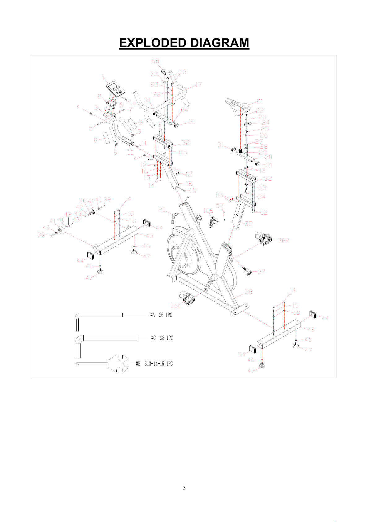
EXPLODED DIAGRAM
4
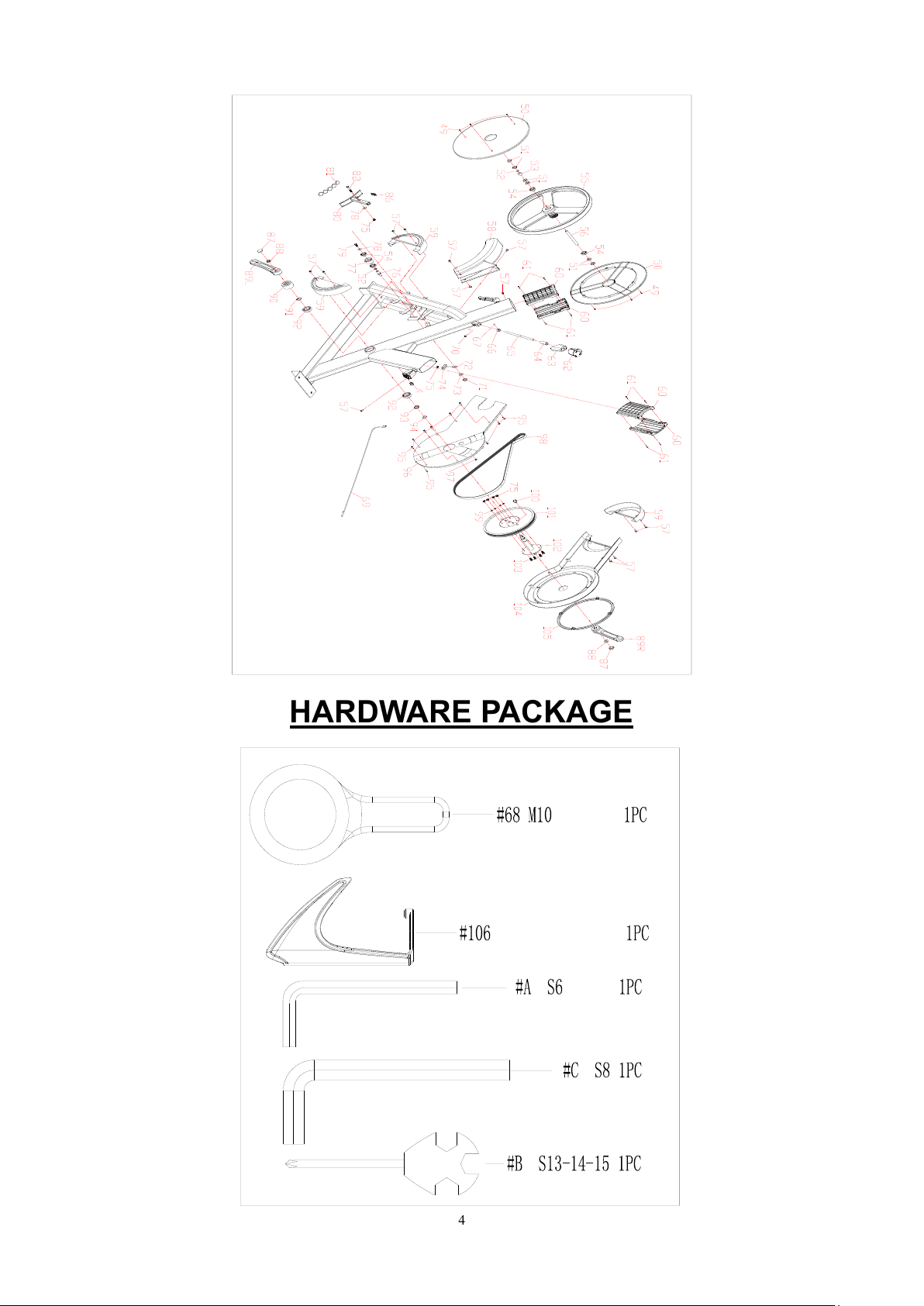
HARDWARE PACKAGE
5
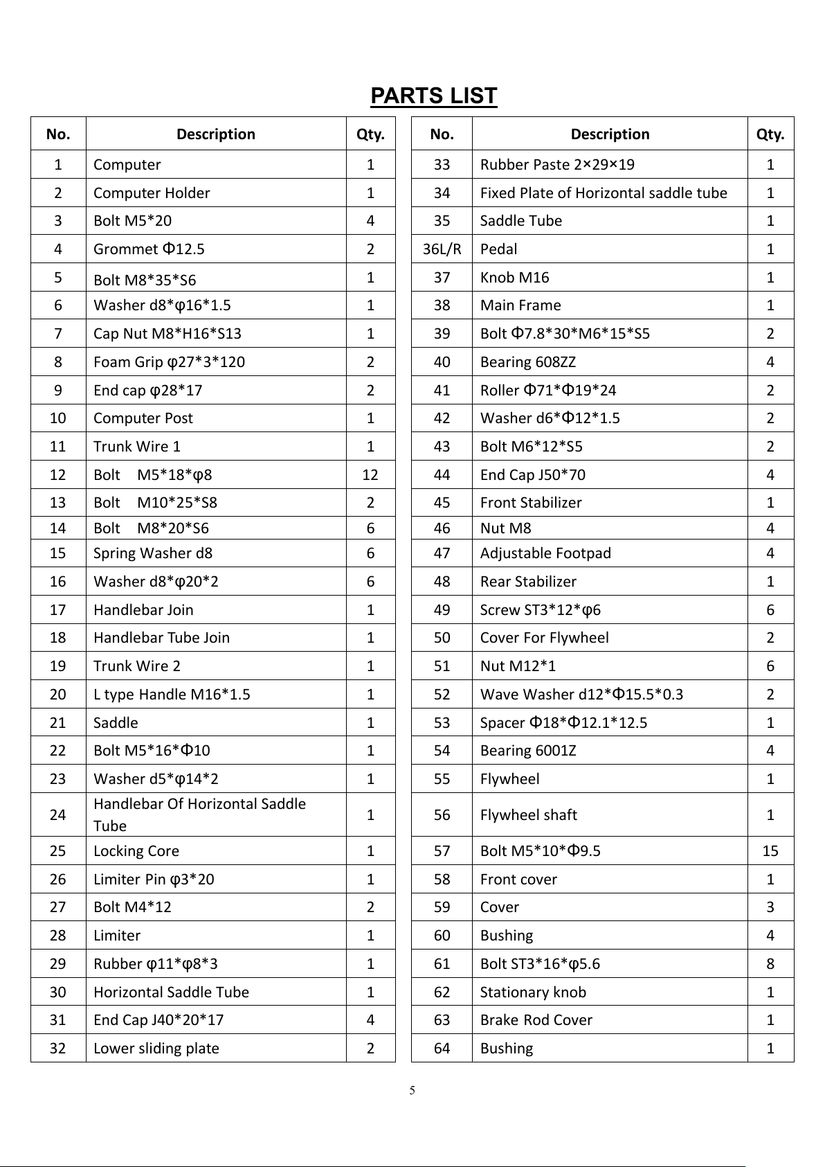
PARTS LIST
No.
Description
Qty.
No.
Description
Qty.
1
Computer
1
33
Rubber Paste 2×29×19
1
2
Computer Holder
1
34
Fixed Plate of Horizontal saddle tube
1
3
Bolt M5*20
4
35
Saddle Tube
1
4
Grommet Φ12.5
2
36L/R
Pedal
1
5
Bolt M8*35*S6
1
37
Knob M16
1
6
Washer d8*φ16*1.5
1
38
Main Frame
1
7
Cap Nut M8*H16*S13
1
39
Bolt Φ7.8*30*M6*15*S5
2
8
Foam Grip φ27*3*120
2
40
Bearing 608ZZ
4
9
End cap φ28*17
2
41
Roller Φ71*Φ19*24
2
10
Computer Post
1
42
Washer d6*Φ12*1.5
2
11
Trunk Wire 1
1
43
Bolt M6*12*S5
2
12
Bolt M5*18*φ8
12
44
End Cap J50*70
4
13
Bolt M10*25*S8
2
45
Front Stabilizer
1
14
Bolt M8*20*S6
6
46
Nut M8
4
15
Spring Washer d8
6
47
Adjustable Footpad
4
16
Washer d8*φ20*2
6
48
Rear Stabilizer
1
17
Handlebar Join
1
49
Screw ST3*12*φ6
6
18
Handlebar Tube Join
1
50
Cover For Flywheel
2
19
Trunk Wire 2
1
51
Nut M12*1
6
20
L type Handle M16*1.5
1
52
Wave Washer d12*Φ15.5*0.3
2
21
Saddle
1
53
Spacer Φ18*Φ12.1*12.5
1
22
Bolt M5*16*Φ10
1
54
Bearing 6001Z
4
23
Washer d5*φ14*2
1
55
Flywheel
1
24
Handlebar Of Horizontal Saddle
Tube
1
56
Flywheel shaft
1
25
Locking Core
1
57
Bolt M5*10*Φ9.5
15
26
Limiter Pin φ3*20
1
58
Front cover
1
27
Bolt M4*12
2
59
Cover
3
28
Limiter
1
60
Bushing
4
29
Rubber φ11*φ8*3
1
61
Bolt ST3*16*φ5.6
8
30
Horizontal Saddle Tube
1
62
Stationary knob
1
31
End Cap J40*20*17
4
63
Brake Rod Cover
1
32
Lower sliding plate
2
64
Bushing
1
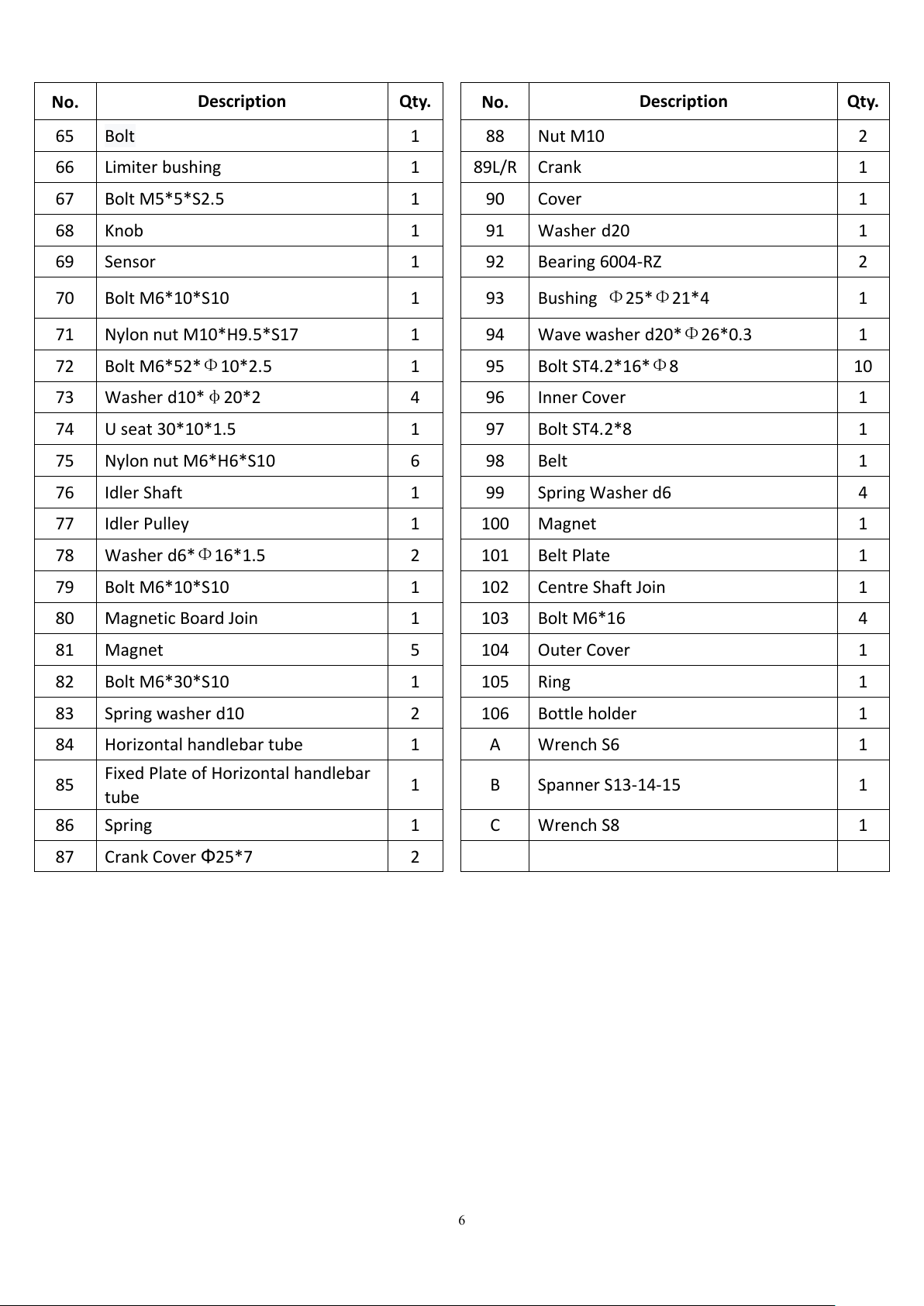
6
No.
Description
Qty.
No.
Description
Qty.
65
Bolt
1
88
Nut M10
2
66
Limiter bushing
1
89L/R
Crank
1
67
Bolt M5*5*S2.5
1
90
Cover
1
68
Knob
1
91
Washer d20
1
69
Sensor
1
92
Bearing 6004-RZ
2
70
Bolt M6*10*S10
1
93
Bushing Φ25*Φ21*4
1
71
Nylon nut M10*H9.5*S17
1
94
Wave washer d20*Φ26*0.3
1
72
Bolt M6*52*Φ10*2.5
1
95
Bolt ST4.2*16*Φ8
10
73
Washer d10*φ20*2
4
96
Inner Cover
1
74
U seat 30*10*1.5
1
97
Bolt ST4.2*8
1
75
Nylon nut M6*H6*S10
6
98
Belt
1
76
Idler Shaft
1
99
Spring Washer d6
4
77
Idler Pulley
1
100
Magnet
1
78
Washer d6*Φ16*1.5
2
101
Belt Plate
1
79
Bolt M6*10*S10
1
102
Centre Shaft Join
1
80
Magnetic Board Join
1
103
Bolt M6*16
4
81
Magnet
5
104
Outer Cover
1
82
Bolt M6*30*S10
1
105
Ring
1
83
Spring washer d10
2
106
Bottle holder
1
84
Horizontal handlebar tube
1
A
Wrench S6
1
85
Fixed Plate of Horizontal handlebar
tube
1
B
Spanner S13-14-15
1
86
Spring
1
C
Wrench S8
1
87
Crank Cover Φ25*7
2

7
ASSEMBLY INSTRUCTIONS
STEP 1:
A. Take out the bolts(14), spring washers(15) and washers(16) from front stabilizer
(45) and rear stabilizer (48) by wrench (A).
B. Attach front stabilizer (45) and rear stabilizer (48) to main frame(38) with the
bolts(14), spring washers(15) and washers(16) by wrench(A).
8
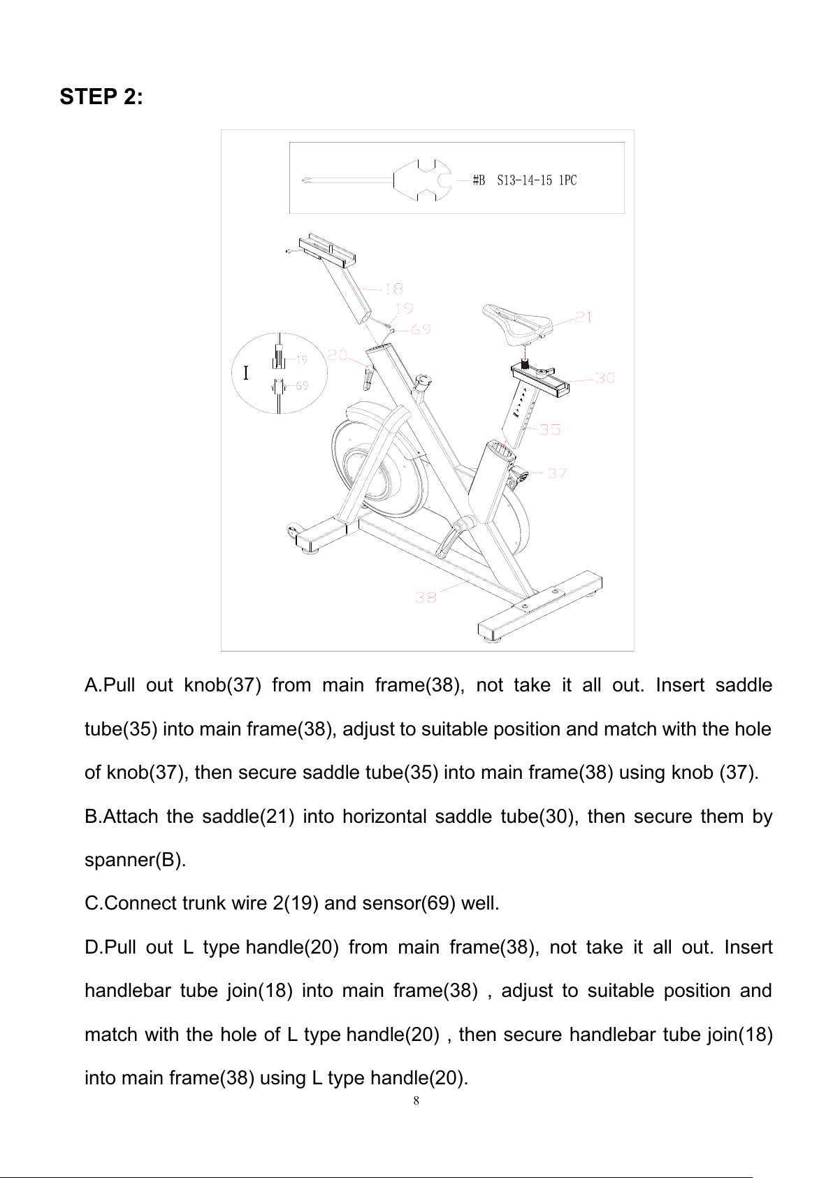
STEP 2:
A.Pull out knob(37) from main frame(38), not take it all out. Insert saddle
tube(35) into main frame(38), adjust to suitable position and match with the hole
of knob(37), then secure saddle tube(35) into main frame(38) using knob (37).
B.Attach the saddle(21) into horizontal saddle tube(30), then secure them by
spanner(B).
C.Connect trunk wire 2(19) and sensor(69) well.
D.Pull out L type handle(20) from main frame(38), not take it all out. Insert
handlebar tube join(18) into main frame(38) , adjust to suitable position and
match with the hole of L type handle(20) , then secure handlebar tube join(18)
into main frame(38) using L type handle(20).

9
STEP 3:
11
19
18
10
16
15
14
A.Take out the bolts(14), spring washers(15) and washers(16) from handlebar
tube join(18) by wrench(A).
B.Connect trunk wire 1(11) and trunk wire 2(19) well.
C.Insert wire into computer post(10), then insert computer post(10) into
handlebar tube join(18), and secure them using bolts(14), spring washers(15)
and washers(16) by wrench (A).
10
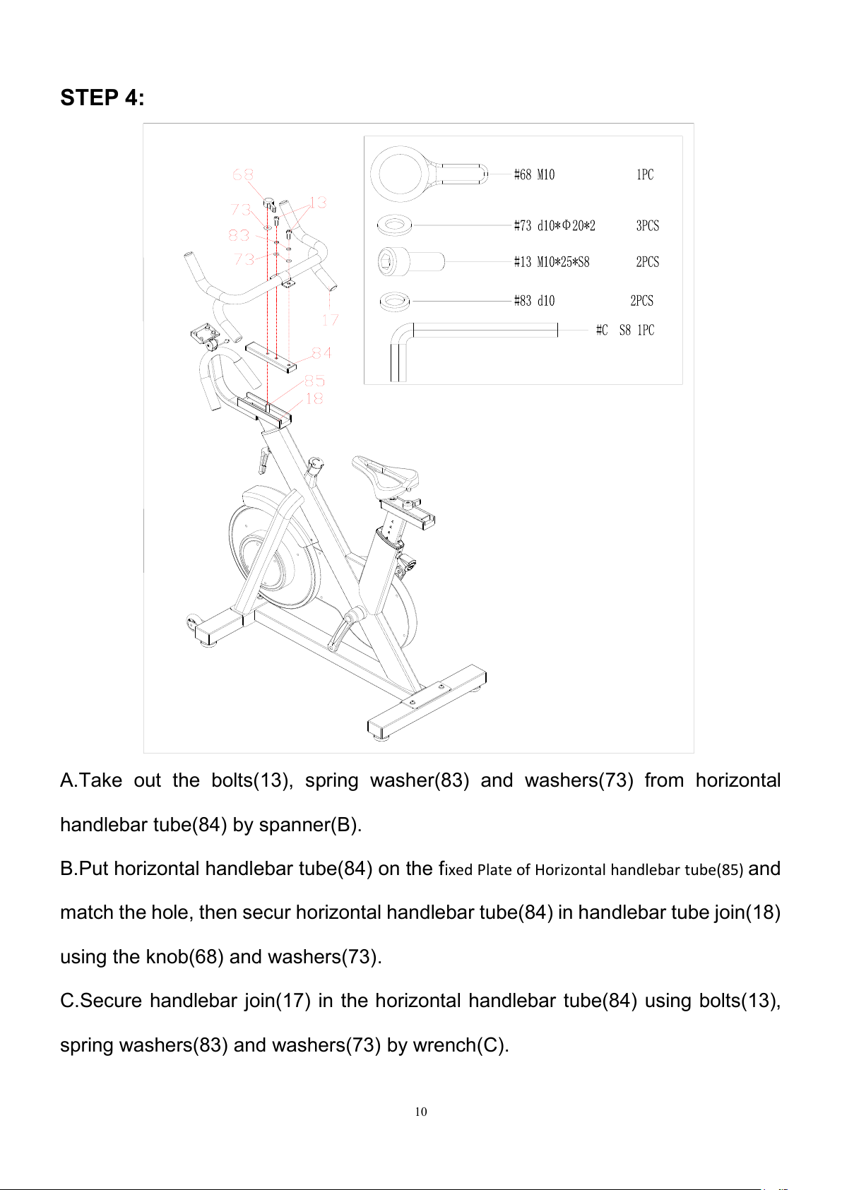
STEP 4:
A.Take out the bolts(13), spring washer(83) and washers(73) from horizontal
handlebar tube(84) by spanner(B).
B.Put horizontal handlebar tube(84) on the fixed Plate of Horizontal handlebar tube(85) and
match the hole, then secur horizontal handlebar tube(84) in handlebar tube join(18)
using the knob(68) and washers(73).
C.Secure handlebar join(17) in the horizontal handlebar tube(84) using bolts(13),
spring washers(83) and washers(73) by wrench(C).
11
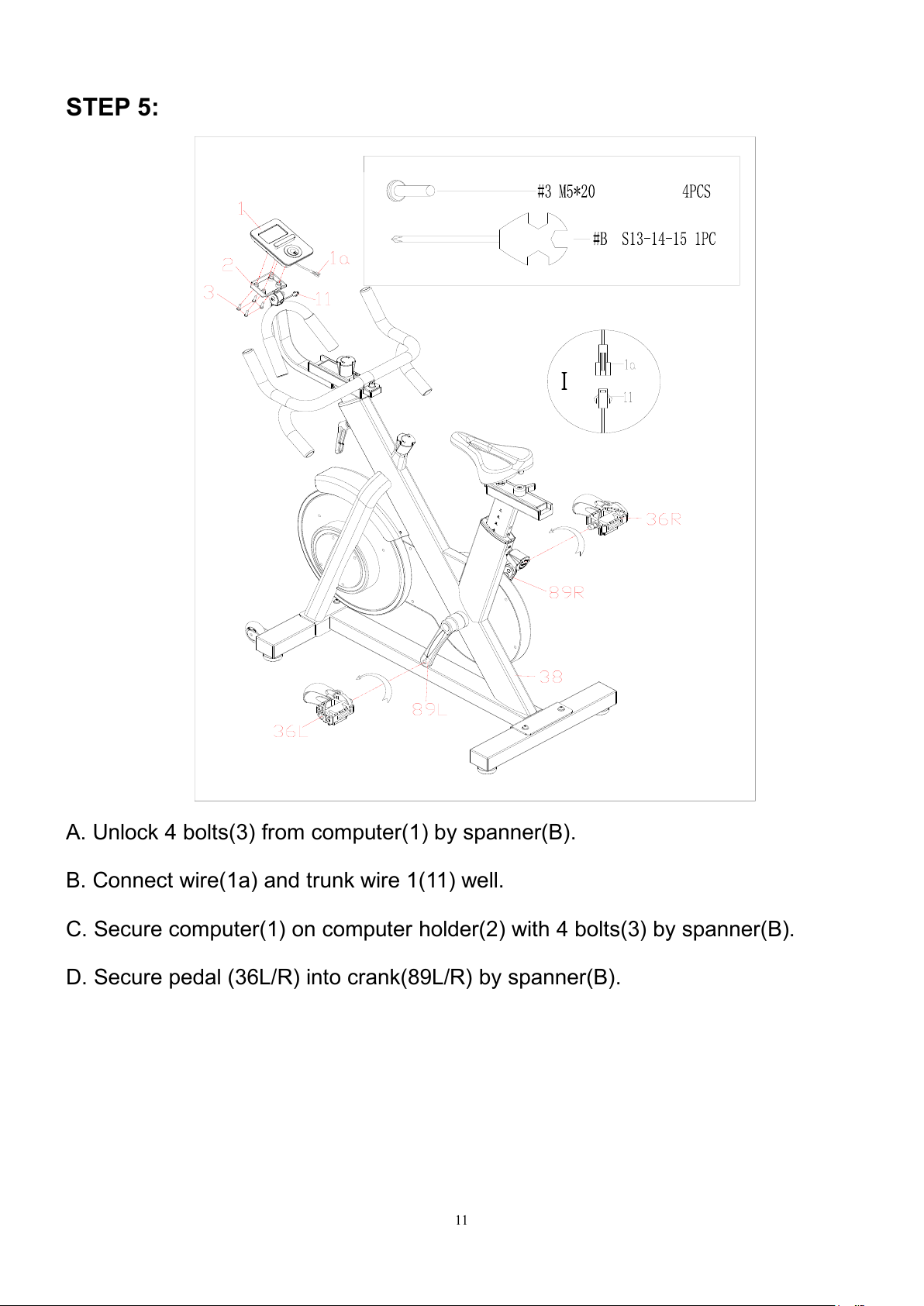
STEP 5:
A. Unlock 4 bolts(3) from computer(1) by spanner(B).
B. Connect wire(1a) and trunk wire 1(11) well.
C. Secure computer(1) on computer holder(2) with 4 bolts(3) by spanner(B).
D. Secure pedal (36L/R) into crank(89L/R) by spanner(B).
12
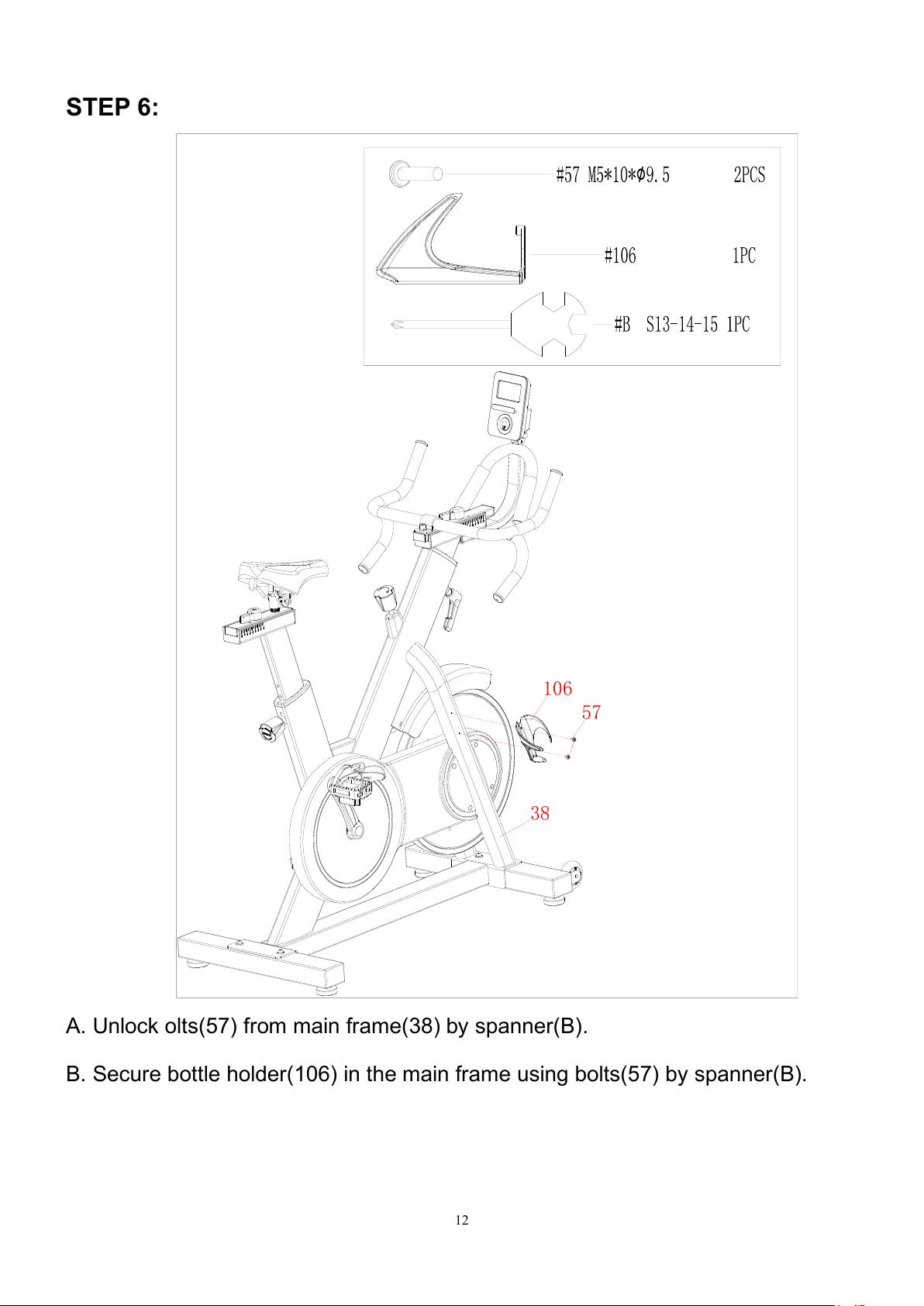
STEP 6:
57
106
38
A. Unlock olts(57) from main frame(38) by spanner(B).
B. Secure bottle holder(106) in the main frame using bolts(57) by spanner(B).

13
MOVING THE MACHINE
To move the machine, push the handlebar join(17) until the
transportation wheels on the front stabilizer(45) touch the ground. With
the wheels on the ground, you can transport the bike to the desired
location with ease.
ADJUSTMENTS GUIDE
1. ADJUSTING THE RESISTANCE
As showed in figure: Rotate stationary
knob(62) clockwise to increase the level of
resistance, rotate the knob
counter-clockwise to decrease the level of
resistance.
14
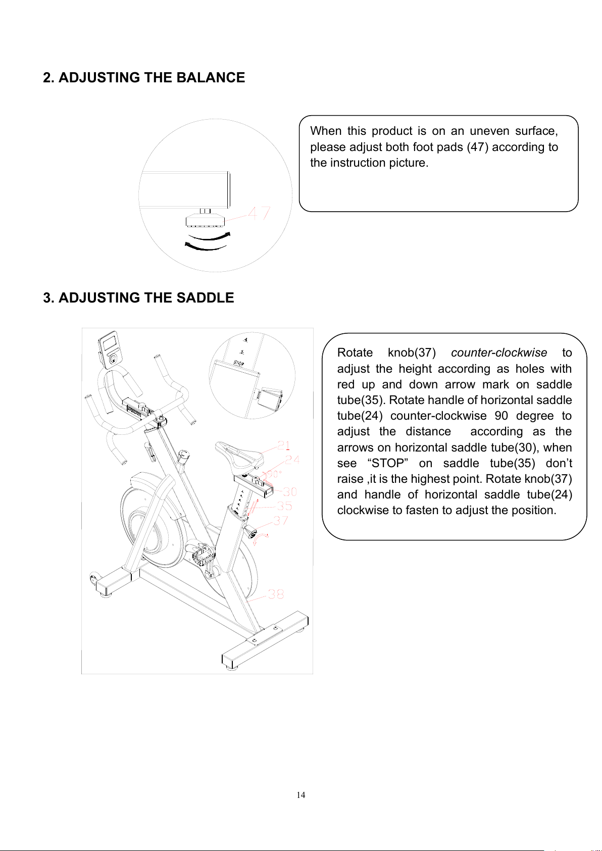
2. ADJUSTING THE BALANCE
3. ADJUSTING THE SADDLE
When this product is on an uneven surface,
please adjust both foot pads (47) according to
the instruction picture.
Rotate knob(37) counter-clockwise to
adjust the height according as holes with
red up and down arrow mark on saddle
tube(35). Rotate handle of horizontal saddle
tube(24) counter-clockwise 90 degree to
adjust the distance according as the
arrows on horizontal saddle tube(30), when
see “STOP”on saddle tube(35) don’t
raise ,it is the highest point. Rotate knob(37)
and handle of horizontal saddle tube(24)
clockwise to fasten to adjust the position.
15
EXERCISE COMPUTER WITH PULSE
INSTRUCTION MANUAL
BUTTONS
1. MODE
Press it to select functions .
FUNCTIONS
1.SPEED
i. Display instantaneous speed and the range is 0.0~99.9KM/H.Or,if the monitor showing
M, the range will be 0.0~99.9MILE/H.The max. pickup signal is 1500rpm.
ii. Display current repetition per minute(RPM) during exercise. It reflects the pedal
frequency. The range is 0~1500 rate per minute.
2.TIME
i. Count the total time from exercise start to the end and the range is 0 ~ 99M59S.
3.DISTANCE
i. Count the total distance from exercise start to the end and the range is 0.00 ~ 9.99 ~
99.9KM. Or, if the meter showing M, the range will be 0.00 ~ 9.99 ~ 99.9 MILE.
4. CALORIES/TEMPERATURE
i. Count the total calories consumed from exercise start to the end and the range is 0.0 ~
99.9 ~ 999KCAL.
ii. Display room temperature(TEMP).
5. PULSE
i. Hold the wireless pulse sensor and read your heart rate per minute. The range is 40 ~
240bpm.
6. AUTO ON/OFF & AUTO START/STOP
i. Without any signal of exercise or operation for 8 minutes, the power will turn off
automatically.
ii. Once receive exercise or operation signal, the monitor will turn on automatically.
OPERATION
PULSE RATE
Remark: During the process of wireless pulse sensor measurement, because of the contact
jamming, the measurement value may be higher than the virtual pulse rate during the first 2~3
seconds, then will return to normal level. If the computer have wireless pulse receive , Please
exactitude use wireless pulse shoot
BATTERY REPLACE
When the display becomes dim or illegible, remove the battery and replace with SIZE AAA UM4
R03.

GARLANDO SPA
Via Regione Piemonte, 32 - Zona Industriale D1
15068 - Pozzolo Formigaro (AL) - Italy
www.toorx.it - info@toorx.it
Table of contents
Other Garlando Exercise Bike manuals


Popular Exercise Bike manuals by other brands


Cateye
Cateye EC3600E operating instructions

Sunny Health & Fitness
Sunny Health & Fitness ELITE INTERACTIVE SF-RBE420049 user manual

Impex
Impex Sports Authority Bodyfit BFA-2800 manual

Healthware Fit
Healthware Fit CP-375R owner's manual

Trojan
Trojan SHAPE 210 user manual

Impex
Impex MARCY NS-714U owner's manual


