Garmin GSI 10 User manual
GSI™10
INSTALLATION INSTRUCTIONS
Important Safety Information
WARNING
Failure to follow these warnings, cautions, and notices could result in personal injury, damage to the vessel or
device, or poor product performance.
See the Important Safety and Product Information guide in the product box for product warnings and other
important information.
When connecting the power cable, do not remove the in-line fuse holder. To prevent the possibility of injury or
product damage caused by fire or overheating, the appropriate fuse must be in place as indicated in the product
specifications. In addition, connecting the power cable without the appropriate fuse in place voids the product
warranty.
CAUTION
To avoid possible personal injury, always wear safety goggles, ear protection, and a dust mask when drilling,
cutting, or sanding.
To avoid possible personal injury or damage to the device and vessel, disconnect the vessel's power supply
before beginning to install the device.
To avoid possible personal injury or damage to the device or vessel, before applying power to the device, make
sure that it has been properly grounded, following the instructions in the guide.
NOTICE
For the best possible performance, the device must be installed according to these instructions.
When drilling or cutting, always check what is on the opposite side of the surface to avoid damaging the vessel.
Read all installation instructions before proceeding with the installation. If you experience difficulty during the
installation, contact Garmin® Product Support.
Mounting Considerations
NOTICE
This device should be mounted in a location that is not exposed to extreme temperatures or conditions. The
temperature range for this device is listed in the product specifications. Extended exposure to temperatures
exceeding the specified temperature range, in storage or operating conditions, may cause device failure.
Extreme-temperature-induced damage and related consequences are not covered by the warranty.
• You must mount the device in a location where it will not be submerged.
• You must mount the device in a location with adequate ventilation where it will not be exposed to extreme
temperatures.
• You must mount the device at least 2.54cm (1in.) from cables and other potential sources of interference.
• You must mount the device in a location that allows room for the routing and connection of all cables.
GUID-64AF40E4-05B2-4037-9A6C-F709B96CA9EA v4July 2022

Mounting the GSI 10 Black Box Device
NOTICE
If you are mounting the device in fiberglass, when drilling the pilot holes, use a countersink bit to drill a
clearance counterbore through only the top gel-coat layer. This will help to avoid cracking in the gel-coat layer
when the screws are tightened.
NOTE: Screws are included with the device, but they may not be suitable for the mounting surface.
Before you mount the device, you must select a mounting location, and determine what screws and other
mounting hardware are needed for the surface.
1Place the black box device in the mounting location, and mark the location of the pilot holes.
2Drill a pilot hole for one corner of the device.
3Loosely fasten the device to the mounting surface with one corner, and examine the other three pilot-hole
marks.
4Mark new pilot-hole locations if necessary, and remove the device from the mounting surface.
5Drill the remaining pilot holes.
6Secure the device to the mounting location.
Connection Considerations
When connecting this device to power and to other Garmin devices, you should observe these considerations.
• The power and ground connections to the battery must be checked to make sure they are secured and
cannot become loose.
• The cables may be packaged without the locking rings installed. The cables should be routed before the
locking rings are installed.
• After installing a locking ring on a cable, you should make sure the ring is securely connected and the o-ring
is in place so the power or data connection remains secure.
Connection Overview
NOTE: The cable connections to the GSI 10 device shown in this diagram are the only connections needed when
installing the device. All of the other connectors are not functional and should not be used.
2

Item Description Notes
Garmin radar
GSI 10 Garmin Sensor
Interface
Garmin Marine Network
cable
You must use a Garmin Marine Network cable to connect Garmin devices
together.
You must not use a Garmin Marine Network cable to connect your computer
or other third-party device to the GSI 10.
Garmin power cable You must connect the GSI 10 and a Garmin radar to a power source following
the instructions provided with the device.
Ethernet cable adapter
(included)
NOTICE
To avoid possible damage to the device and to ensure that the cable and
adapter function properly, you must install the adapter and make the connec
tions in a dry location.
You must use the included Ethernet cable adapter and a standard Ethernet
cable (not included) to connect your computer or other third-party device to
the GSI 10.
You must not connect your computer or other third-party device to a
NETWORK port on the GSI 10.
3

Item Description Notes
Standard CAT5e or
CAT6 Ethernet cable
(not included)
NOTICE
To avoid possible damage to the device and to ensure that the cable and
adapter function properly, you must install the adapter and make the connec
tions in a dry location.
You must use a standard Ethernet cable (not included) to connect your
computer or other third-party device to the GSI 10 through the included
Ethernet cable adapter.
Power source
Computer or other third-
party device
Connector View
4

Status LED
Not used
POWER Power cable port
NETWORK
Garmin Marine Network ports. Used to connect an approved Garmin Marine Network device,
such as a radar.
NOTE: You must not connect a computer to any NETWORK port using an Ethernet cable. You
must connect a computer to the USB HOST port using the included USB Ethernet adapter.
CVBS IN Not used
Water ground (Additional Grounding Consideration, page6)
Power button
The device turns on automatically when power is applied, so it is not necessary to use the power
button for normal operation.
If needed, you can turn off the device by holding the power button for 10 seconds. You can turn it
back on again by pressing the power button.
NMEA 0183 Not used
USB HOST Micro-USB port for connecting the included Ethernet cable adapter.
USB OTG Micro-USB input from a compatible Garmin card reader1, computer, or other supported USB
accessory
NMEA 2000 Not used
J1939 Not used
Connecting to Power
WARNING
When connecting the power cable, do not remove the in-line fuse holder. To prevent the possibility of injury or
product damage caused by fire or overheating, the appropriate fuse must be in place as indicated in the product
specifications. In addition, connecting the power cable without the appropriate fuse in place voids the product
warranty.
You should connect the red wire to the power source through the ignition or another manual switch to turn the
device on and off.
1Route the power cable between the power source and the device.
2Connect the red power wire to the ignition or another manual switch, and connect the switch to the positive
(+) battery terminal if necessary.
3Connect the black wire to the negative (-) battery terminal or to ground.
4Connect the power cable to the device, and turn the locking ring clockwise to tighten it.
1 Only compatible Garmin card readers are recommended. Third-party card readers are not guaranteed to be fully compatible.
5
Additional Grounding Consideration
This device should not need additional chassis grounding in most installation situations. If you experience
interference, you can use the grounding screw on the housing to connect the device to the water ground of the
boat to help avoid the interference.
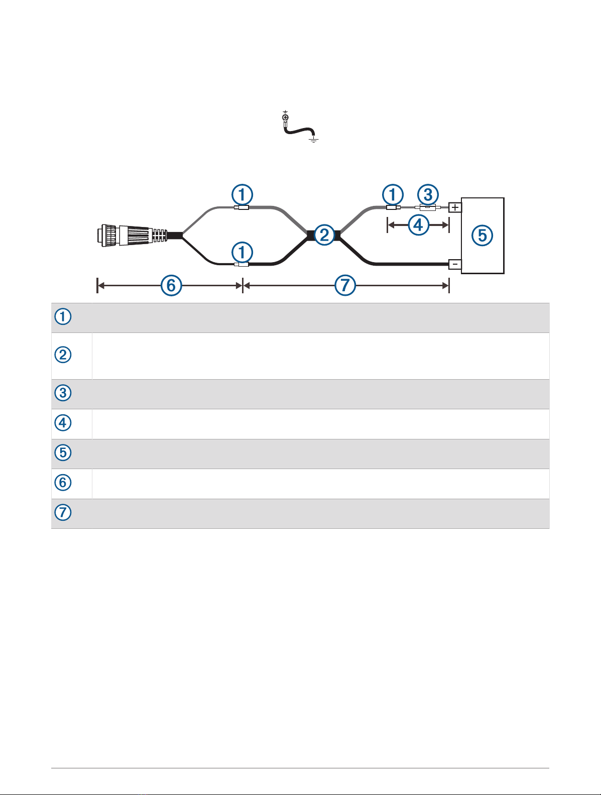
Power Cable Extensions
If necessary, the power cable can be extended using the appropriate wire gauge for the length of the extension.
Splice
• Up to 4.6m (15 ft.): 10AWG (5.26mm2) extension wire
• Up to 7m (23 ft.): 8AWG (8.36mm2) extension wire
• Up to 11m (36 ft.): 6AWG (13.29mm2) extension wire
Fuse (10 A, 42 V fast-acting)
20.3cm (8in.)
Battery
20.3cm (8in.)
11m (36 ft.) maximum extension
Power Considerations
While you can turn the GSI 10 device off and on using the power key, the it will likely not be easily accessible to
do so. You should install a switch on the power cable to turn it on and off.
When power is applied to the device, it turns on. You cannot disable the automatic power-on feature.
6

Garmin Marine Network Considerations
NOTICE
You must not connect any third-party device, such as a FLIR® camera, to a NETWORK port on this device.
Connecting an unapproved device may damage the Garmin device, may damage the third-party device, and will
cause abnormal behavior on the Garmin devices, including inoperable software.
This device can connect to approved Garmin Marine Network devices to provide specific data to a computer
or third-party system using the Garmin Marine Sensor Interface API. When connecting approved Garmin Marine
Network devices to this device, observe these considerations.
• All devices connected to the Garmin Marine Network must be connected to the same ground. If multiple
power sources are used for Garmin Marine Network devices, you must tie all ground connections from all
power supplies together using a low resistance connection or tie them to a common ground bus bar, if
available.
• A Garmin Marine Network cable must be used for all Garmin Marine Network connections.
◦Third-party CAT5e or CAT6 Ethernet cable and RJ45 connectors must not be used for Garmin Marine
Network connections.
◦Additional Garmin Marine Network cables and connectors are available from your Garmin dealer.
• The NETWORK ports on the device each act as a network switch. Any approved device can be connected to
any NETWORK port to share data.
• You must not connect your computer or third party device to this device using a NETWORK port. You must
connect your system or computer using the included Ethernet cable adapter.
Installing Ferrite Beads on the Cables
To comply with regulations and to reduce electromagnetic interference (EMI) or "noise", you must install ferrite
beads on the power cable and the Garmin Marine Network cables.
• You must install one ferrite bead on the power cable, near the connector.
• You must install two ferrite beads on each Garmin Marine Network cable in use, one near each connector.
Five ferrite beads are included. If your installation uses more than two Garmin Marine Network cables, you must
purchase additional ferrite beads from your Garmin dealer to install on the additional cables.
1Make a small loop in the power cable or Garmin
Marine Network cable near the connector to create
a doubled section of the cable.
The doubled section of the cable helps to hold the
bead in place without sliding.
2Place the doubled area of the cable inside the open
ferrite bead.
3Securely snap the ferrite bead closed.
4For a Garmin Marine Network cable, repeat steps 1
through 3 on the other end of the cable.
5Repeat this procedure for additional Garmin Marine Network cables as needed.
7

Ethernet Connection Considerations
NOTICE
The connections between the Ethernet cable adapter, the GSI 10, and the Ethernet cable are not water resistant.
You must install the adapter and make the connections in a dry location.
This device shares data from approved Garmin Marine Network devices to your computer or third-party device
using the Garmin Marine Sensor Interface API.
You must connect the included Ethernet cable adapter to the USB HOST port on this device.
You must connect your computer or third-party device to the Ethernet cable adapter using a standard CAT5e or
CAT6 Ethernet cable (not included).
You must not connect your computer or third-party device directly to this GSI 10 using one of the NETWORK
ports. The NETWORK ports are compatible with approved Garmin Marine Network devices only.
Specifications
Dimensions (W × H × D) 38.3 × 19.8 × 4.7cm (151/8× 713/16× 17/8in.)
Clearance on front of device 8.6cm (33/8 in.)
Weight 1.39kg (3.06lb.)
Compass-safe distance 2.54cm (1in.)
Temperature range From -15° to 55°C (from 5° to 131°F)
Material Polycarbonate plastic and die-cast aluminum
GSI 10 water rating IEC 60529 IPX7 2
Ethernet cable adapter water rating Not water resistant (must be installed in a dry location).
Fuse 10 A, 42 V fast-acting
Input voltage From 10 to 32Vdc
Max. power usage at 10Vdc 40.1W
Typical current draw at 12Vdc 1.5A
Max. current draw at 12Vdc 6.0A
Memory card External card reader required (not included)
Status LED
LED Activity Status
Solid red The device is turning on.
Flashing green The device is operating normally.
Flashing orange The device software is being updated.
© 2021 Garmin Ltd. or its subsidiaries
Garmin® and the Garmin logo are trademarks of Garmin Ltd. or its subsidiaries, registered in the USA and other countries. GSI™ is a trademark of Garmin Ltd. or its
subsidiaries. These trademarks may not be used without the express permission of Garmin.
FLIR® is a registered trademark of FLIR Systems, Inc. NMEA®, NMEA 2000®, and the NMEA 2000 logo are registered trademarks of the National Marine Electronics
Association.
M/N: B03608
2 The device withstands incidental exposure to water of up to 1m for up to 30min. For more information, go to www.garmin.com/waterrating.
© 2021 Garmin Ltd. or its subsidiaries support.garmin.com
Table of contents
Other Garmin Recording Equipment manuals


