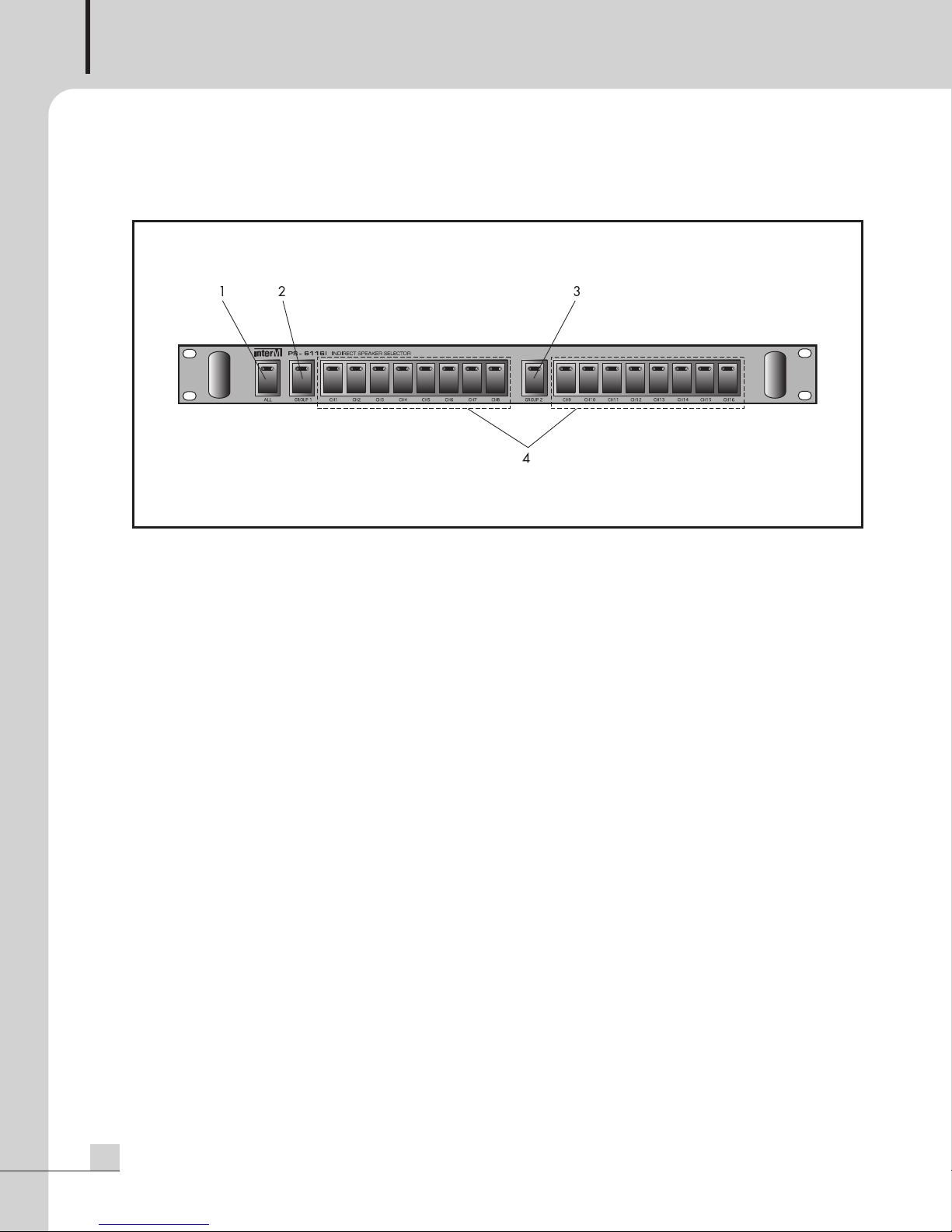
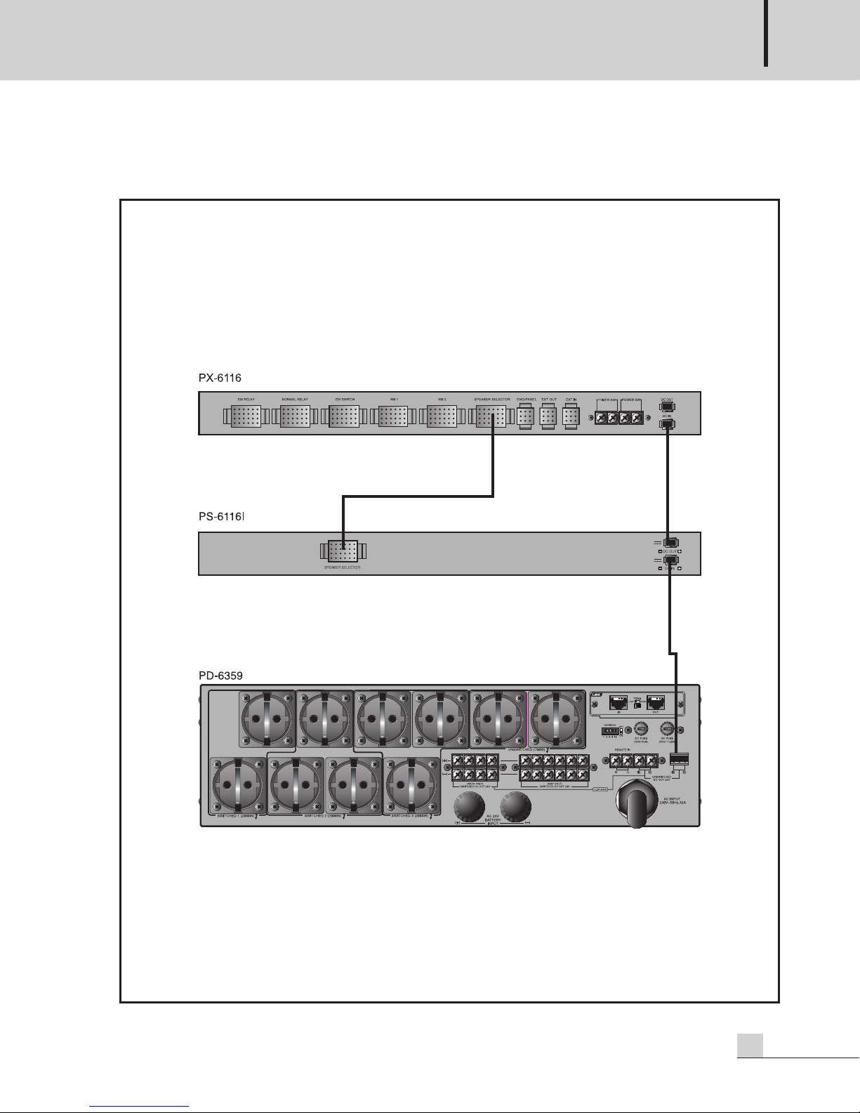
Inter-m PS-6116I User manual

Operation Manual
Speaker Selector
PS-6116I
* Rack mount products in th W st rn H misph r (North Am rica, South Am rica, and th Caribb an)
do not hav handl s install d du to custom r pr f r nc .

SPEAKER SELECTOR
Welcome
Welcome
A personal welcome to you from the management and employees of Inter-M
All of th co-work rs h r at Int r-M ar d dicat d to providing xc ll nt products with inh r ntly good valu ,
and w ar d light d you hav purchas d on of our products.
W sinc r ly trust this product will provid y ars of satisfactory s rvic , but if anything is not to your compl t
satisfaction, w will nd avor to mak things right.
W lcom to Int r-M, and thank you for b coming part of our worldwid xt nd d family!
RI K OF ELECTRIC HOCK
DO NOT OPEN
CAutION
CAUTION: TO REDUCE THE RI K OF ELECTRIC HOCK.
DO NOT REMOVE COVER (OR BACK).
NO U ER- ERVICEABLE PART IN IDE.
REFER ERVICING TO QUALIFIED ERVICE PER ONNEL.
WARNING
To prevent fire or shock hazard, do not
expose the unit to rain or moisture.
*WARNING FOR YOUR PROTECTION PLEA E READ THE FOLLOWING-WATER AND MOI TURE: Unit should not be used near water(e.g.
near a bathtub, washbowl, kitchen sink, laundry tub, in a wet basement, or near a swimming pool, etc). Care should be taken so than objects do
not fall and liquids are not spilled into the enclosure through openings.
*CLA 2 WIRING (Adjacent to speaker terminal): The speaker output of this apparatus can exceed 10 Watts and could be a shock injury.
Connection to speakers should be performed by a skilled person.
*Do not install this equipment in a confined space such as a book case or similar unit.
*This apparatus shall not be exposed to dripping or splashing and no objects filled with liquids, such vases, shall be placed on the apparatus.
*This apparatus shall be connected to a mains socket outlet with a protective earthing connection.
*
It has heed to be easy to disconnect the device. To disconnect the device from power, separate AC input cable from inlet or unplug the AC Cord.
*
The socket-outlet shall be installed near the equipment and shall be easily accessible.
CAutION
*These servicing instructions are for use by qualified service personnel only. To reduce the risk of electric shock, do not perform any servicing
other than that contained in the operating instructions unless you are qualified to do so.
NOtE
*This equipment has been tested and found to comply with the limits for a Class A digital device, pursuant to Part 15 of the FCC Rules. These limits are
designed to provide reasonable protection against harmful interference when the equipment is operated in a commercial environment. This equipment
generates, uses, and can radiate radio frequency energy and, if not installed and used in accordance with the instruction manual, may cause harmful
interference to radio communications. Operation of this equipment in a residential area is likely to cause harmful interference in which case the user will
be required to correct the interference at his own expense.
This symbol is intended to alert the user to the
presence of uninsulated “dangerous voltage” within
the product’s enclosure that may be of sufficient
magnitude to constitute a risk of electric shock to
persons.
This symbol is intended to alert the user to the
presence of important operation and maintenance
(servicing) instructions in the literature accompanying
the appliance.
Caution: To prevent electric shock do not use this (polarized) plug with
an extension cord, receptacle or other outlet unless the blades
can be fully inserted to prevent blade exposure.
Attentions: Pour prévenir les chocs électriques ne pas utiliser cette
fiche polarisée avec un prolongateur, une prise de courant
on une autre sortie de courant, sauf si les lames peuvent
étre insérées à fond sans en laisser aucune partie à
découvert.

SPEAKER SELECTOR
1
PS-6116I
Contents
Contents
Unpacking .......................................................................................................................................2
Installation
Environm nt....................................................................................................................................2
Important Saf ty Instructions.............................................................................................................2
Features............................................................................................................................................3
Operation ........................................................................................................................................3
Front Panel ......................................................................................................................................4
Rear Panel .......................................................................................................................................5
Pinouts..............................................................................................................................................6
Applications ....................................................................................................................................7
Block Diagram ................................................................................................................................8
Specifications ..................................................................................................................................9
Service............................................................................................................................................10
Proc dur s....................................................................................................................................10
Sch matic.....................................................................................................................................10
Parts List .......................................................................................................................................10
Warranty .......................................................................................................................................10

SPEAKER SELECTOR
Unpacking
2PS-6116I
Unpacking
Although your PS-6116I is n ith r complicat d nor difficult to op rat , w r comm nd you tak a f w minut s
to r ad this bri f manual and familiariz yours lf with th important information r garding product f atur s,
s tup and op ration.
As with most l ctronic d vic s, w strongly r comm nd you r tain th original packaging. In th unlik ly v nt
th product must b r turn d for s rvicing, th original packaging (or r asonabl quival nt) is r quir d.
Installation
Installation
Environment
N v r plac this product in an nvironm nt which could alt r its p rformanc or r duc its s rvic lif . Such
nvironm nts usually includ high l v ls of h at, dust, moistur , and vibration.
IMPORTANT SAFETY INSTRUCTIONS
1. R ad th s instructions.
2. K p th s instructions.
3. H d all warnings.
4. Follow all instructions.
5. Do not us this apparatus n ar wat r.
6. Cl an only with dry cloth.
7. Do not block any v ntilation op nings. Install in accordanc with th manufactur r’s instructions.
8. Do not install n ar any h at sourc s such as radiators, h at r gist rs, stov s, or oth r apparatus (including
amplifi rs) that produc h at.
9. Do not d f at th saf ty purpos of th polariz d or grounding-typ plug. A polariz d plug has two blad s
with on wid r than th oth r. A grounding typ plug has two blad s and a third grounding prong. Th wid
blad or th third prong ar provid d for your saf ty. If th provid d plug do s not fit into your outl t, consult
an l ctrician for r plac m nt of th obsol t outl t.
10. Prot ct th pow r cord from b ing walk d on or pinch d particularly at plugs, conv ni nc r c ptacl s, and
th point wh r th y xit from th apparatus.
11. Only us attachm nts/acc ssori s sp cifi d by th manufactur r.
12. Us only with th cart, stand, tripod, brack t, or tabl sp cifi d by th manufactur r, or sold with th apparatus.
Wh n a cart is us d, us caution wh n moving th cart/apparatus combination to avoid injury from tip-ov r.
13. Unplug this apparatus during lightning storms or wh n unus d for long p riods of tim .
14. R f r all s rvicing to qualifi d s rvic p rsonn l. S rvicing is r quir d wh n th
apparatus has b n damag d in any way, such as pow r-supply cord or plug is
damag d, liquid has b n spill d or obj cts hav fall n into th apparatus, th
apparatus has b n xpos d to rain or moistur , do s not op rat normally, or has
b n dropp d.
S3125A
3125A

SPEAKER SELECTOR
3
PS-6116I
Features
Features
- SIXTEEN INDEPENDENT ZONES
Chann l switch s allow you to s l ct any combination of up to 16 zon s ind p nd ntly.
- GROUPING FUNCTION
Group 1, Group 2 and ALL s l ctors ar provid d to s l ct all sp ak r zon s or groups of ight.
- REMOTE CONTROL COMPATIBLE
R ar-pan l t rminals provid d for r mot s l ction of ALL, Group 1 or Group 2.
- CONVENIENT LED INDICATORS
Int grat d LED indicators on ach switch for asy id ntification of curr ntly s l ct d status.
Operation
Operation
Mak c rtain that sp ak rs and input sourc s ar prop rly conn ct d b for switching th unit on.
K p volum l v ls turn d down b for switching on.
※NOTE : Th syst m’s op ration is d lay d by approximat ly thr s conds aft r pr ssing th pow r switch.
This is du to th built-in prot ction circuitry, d sign d to prot ct th sp ak rs and oth r syst m compon nts.
Int grat d LED indicators on ach switch for asy id ntification of curr ntly s l ct d status.

SPEAKER SELECTOR
PS-6116I
Front Panel
Front Panel
1. ALL SWITCH
This switch s l cts all 16 sp ak r outputs simultan ously.
2. GROUP 1 SWITCH
This switch s l cts all Group 1 (chann ls 1 through 8) outputs simultan ously.
3. GROUP 2 SWITCH
This switch s l cts all Group 2 (chann ls 9 through 16) outputs simultan ously.
. CHANNEL SWITCHES
Th s switch s s l ct individual chann ls 1 through 16. Any combination of switch s can b s l ct d
ind p nd ntly.

SPEAKER SELECTOR
5
PS-6116I
Rear Panel
Rear Panel
1. SPEAKER SELECTOR CONNECTOR
This multi-pin conn ctor is for input of th Int r-M PX-6116I Sp ak r Matrix only.
2. DC OUTPUT CONNECTOR
This output is for conn ction of 24V DC pow r supply to an additional unit in th
3. DC INPUT CONNECTOR
This input is for conn ction of 24V DC pow r supply.

SPEAKER SELECTOR
6PS-6116I
Pinouts
Pinouts
Th diagram b low shows th conn ctor pin numb rs for th r ar-pan l conn ctor.

SPEAKER SELECTOR
7
PS-6116I
Applications
Applications

SPEAKER SELECTOR
8PS-6116I
Block Diagram
Block Diagram
1 2 3 4
DC-OUT +24V
DC +24V
DC-IN +24V
5 6 7 8
9 10 11 12
13 14
17 18 19 20
21
SPEAKER
SELECTOR
22 23 24
15 16
ALL
ALL
C
O
M
A
L
L
1 2 3 4 5 6 7 8 9 10 11 12 13 14 15 16
SW SW 1 SW 2 SW 3 SW 4 SW 5 SW 6 SW 7 SW 8GRP 1
COM
SW 9 SW 10 SW 11 SW 12 SW 13 SW 14 SW 15 SW 16
LED16 V
C
C
V
C
C
GRP 2
LED15LED14LED13LED12LED11LED10LED9
GRP 2
LED8LED7LED6LED5LED4LED3LED2LED1
GRP 1
ALL

SPEAKER SELECTOR
9
PS-6116I
Specifications
Specifications
* Sp cifications and d sign ar subj ct to chang without notic .
280
440
44
482
32
※ DIMENSIONS
PS-6116I
ELECTRICAL
Sp ak r S l ction 16 Chann ls, All, Group 1, Group 2
Indicators 16 Chann ls, All, Group 1, Group 2
Curr nt Rating 1A
Chann l S l ctor 1A
All, Group 1, Group 2 S l ctor 16A, 8A
GENERAL
Pow r Sourc 24VDC
W ight 3kg/6.6lb
Dim nsions 482(W)x44(H)x280(D)mm/19(W)x1.7(H)x11(D)in

SPEAKER SELECTOR
10 PS-6116I
Service
Service
Procedures
Tak st ps to insur th probl m is not r lat d to op rator rror or oth r products within th syst m. Information
provid d in th troubl shooting portion of this manual may h lp with this proc ss. Onc it is c rtain that th
probl m is r lat d to th product contact your warranty provid r as d scrib d in th warranty s ction of this
manual.
Schematic
A Sch matic is availabl by contacting your warranty provid r.
Parts List
A Parts List is availabl by contacting your warranty provid r.
Warranty
Warranty
Warranty t rms and conditions vary by country and may not b th sam for all products. T rms and conditions
of warranty for a giv n product may b d t rmin d first by locating th appropriat country which th product
was purchas d in, th n by locating th product typ .
To obtain sp cific warranty information and availabl s rvic locations contact Int r-M dir ctly or th
authoriz d Int r-M Distributor for your sp cific country or r gion.


MADE IN KOREA
June 2013 133295
Int r-M, Ltd. (Kor a) b gan op rations in 1983.
Sinc th n, Int r-M has grown to b com on of th larg st manufactur rs
of prof ssional audio and comm rcial sound l ctronics quipm nt in th world.
Int r-M has gain d worldwid r cognition for its own brand d products,
as w ll as privat lab l manufacturing of l ctronics sold und r oth r nam s (OEM).
Th company is no long r just a Kor an company, but rath r a global company
that is truly int rnational in scop , with factori s and offic s in Kor a and China,
and sal s and mark ting op rations locat d in Japan, Europ , and th U.S.A.
With mor than 850 mploy s around th glob ,
Int r-M is w ll-pois d for furth r growth and xpansion.
Inter-M Americas, Inc.
13875 Art sia Blvd. C rritos, CA 90703 USA
TEL : +1-562-921-0313, FAX : +1-562-921-0370
Hom Pag : http://www.int r-m.n t, E-mail : info@int r-m.n t
Inter-M Corporation
S oul OFFICE:653-5 BANGHAK-DONG, DOBONG-KU, SEOUL, KOREA
TEL : +82-2-2289-8140~8, FAX : +82-2-2289-8149
Hom Pag : http://www.int r-m.com, E-mail : ov rs as@int r-m.com
Table of contents
Other Inter-m Recording Equipment manuals

Inter-m
Inter-m SEG-1404 User manual

Inter-m
Inter-m DAC-122 User manual

Inter-m
Inter-m PX-6216 User manual

Inter-m
Inter-m PG-6104 User manual

Inter-m
Inter-m PX-6216 User manual

Inter-m
Inter-m PS-6116 User manual

Inter-m
Inter-m MVF-2132 User manual

Inter-m
Inter-m RG-6116 User manual

Inter-m
Inter-m NPX-8000 User manual

Inter-m
Inter-m SYSTEM-2240G User manual
Popular Recording Equipment manuals by other brands

Chameleon Labs
Chameleon Labs 7802 owner's manual

TrueVoice Communications
TrueVoice Communications ACR-B040 user manual

Amperes
Amperes LS 4600 instruction manual

Lutron Electronics
Lutron Electronics RadioRA RA-RS232 Setup and installation guide

Pulsar
Pulsar Smasher user manual

SMART SHOW
SMART SHOW AirPixel Mini II Installation & use