Garrick Machine Tools DP20 User manual
INDUSTRIAL PEDESTAL DRILL PRESS
Model DP20
INDUSTRIAL BENCH DRILL PRESS
Model DB20
INSTRUCTION MANUAL
For your safety, read all instructions carefully.
ISO-9001:2008 Certied

DRILL PRESS MANUAL
We reserve the right of the amendment addition and deletion of the
specifications, explanatory wording, etc. printed in this manual
2
WARNING
Some dust created by power sanding, sawing, grinding, drilling, and
other construction activities contains chemicals known to the State of
California to cause cancer, birth defects or other reproductive harm.
Some examples of these chemicals are:
• Lead from lead-based paints.
• Crystalline silica from bricks, cement, and other masonry products.
• Arsenic and chromium from chemically treated lumber.
Your risk from these exposures varies, depending on how often you do
this type of work. To reduce your exposure to these chemicals: work in
a well ventilated area, and work with approved safety equipment, such
as those dust masks that are specially designed to filter out
microscopic particles.

DRILL PRESS MANUAL
We reserve the right of the amendment addition and deletion of the
specifications, explanatory wording, etc. printed in this manual
3
Table Of Contents PAGE
1. SAFETY
SAFETY RULES FOR ALL TOOLS............................……......................................…4
ADDITIONAL SAFETY INSTRUCTIONS FOR DRILL PRESS …………..........................….5
2. INTRODUCTION
UNPACKING .............................................…........................................................…………...7
PIECE INVENTORY ..............................…..................................................................7
CLEAN UP.................................................………….............................................................8
SITE CONSIDERATIONS ................….....……..….............................................................8
3. ASSEMBLY
BEGINNING ASSEMBLY .................………......................................................................9
COLUMN/BASE.................................…….....................................................................9
TABLE SUPPORT.............................…………....................................................................9
HEADSTOCK .....................................……………..................................................................11
HANDLES .............................................………………...............................................................11
INSTALLING LIGHT BULB ........................………………..........................................................11
DRILL CHUCK AND ARBOR ................…………...............................................................11
ARBOR REMOVAL ................................……………..............................................................12
4. ADJUSTMENTS
SPEED CHANGES ...............................…………...............................................................12
DEPTH STOP .........................................……………...............................................................13
TABLE ADJUSTMENTS ...........................…………….............................................................14
5. OPERATIONS
TEST RUN....................................................…………….........................................................15
DRILL BIT CHANGES.....................................……………….....................................................15
6. MAINTENANCE
GENERAL .......................................…….....................................................................16
TABLES.............................................……...................................................................16
LUBRICATION..................................……....................................................................16
V-BELT ............................................…......................................................................16
7. TECHICAL DATA .......……………….........................................................................17
8. PARTS LISTS & EXPODED VIEWS .………..............................................17--22

DRILL PRESS MANUAL
We reserve the right of the amendment addition and deletion of the
specifications, explanatory wording, etc. printed in this manual
4
1: SAFETY
Safety Instructions For Power Tools
For Your Own Safety Read Instruction
Manual Before Operating This Equipment
1. Keep work area clear. Cluttered areas and benches invite injuries.
2. Consider work area environment . Do not expose tools to rain. Do not use tools in
damp or wet location. Keep work area well lit .Do not use tools in the presence of
flammable liquids or gases.
3. Guard against electric shock. Avoid body contact with earthed or grounded
surfaces.(e.g. pipes ,radiator ,ranges ,refrigerators ).
4. Keep other person away. Do not let persons ,especially children, involved in the work
touch the tool or the extension cord and keep them away from work area.
5. Store idle tools. When not is use , tools should be stored in a dry locked up place ,out
of reach of children.
6. Do not force the tool. It will do the job better and safer at the rate for which it was
intended.
7. Use the right tool . Do not force small tools to do the job of a heavy duty tool. Do not
use tools for purposes not intended, for example do not use circular saws to cut tree
limbs or logs.
8. Dress properly. Do not wear loose clothing or jewellery, they can be caught in moving
parts. Non-skid footwear is recommended when working outdoors . Wear protective
hair covering to contain long hair.
9. Use protective equipment .Use safety glass. Also use face or dust mask if cutting
operations is dusty.
10. Connect dust extraction equipment. If devices are provided for connection of dust
extraction and collection facilities ensure there are connected and property used.
11. Do not abuse the cord. Never yank the cord to disconnect it from the socket. Keep the
cord away from hear , oil and sharp edges.
12. Secure work. Where possible use clamps or a vice to hold the work. it is safer than
using your hands.
13. Do not overreach. Keep proper footing and balance at all times.
14. Maintain tools with care . Keep tools sharp and clean for better and safer performance.
Follow instruction for lubricating and changing accessories. Inspect tool cords
periodically and if damaged have them repaired by an authorized service facility .
Inspect extension cords periodically and replace if damaged .Keep handles dry, clean
and free from oil and grease.
15. Disconnect tool, When not in use ,before servicing and when changing accessories
such as blades, bit and cutters,disconnect tools from the power supply.
16. Remove adjusting keys and wrenches. Form the habit of checking to see that keys and
adjusting wrenches are removed from the tool before turning it on.
17. Avoid unintentional starting . Ensure switch is “off” position when plugging in.
18. Use outdoor extension leads. When tool is used outdoor only extension cords intended
for outdoor use and so marked.
19. Stay alert. Watch what you are doing , use common sense and do not operate tool
when you are tired.
20. Check damaged parts . Before further use of the tool, it should be carefully checked to
determine that it will operate properly and perform its intended function. Check for

DRILL PRESS MANUAL
We reserve the right of the amendment addition and deletion of the
specifications, explanatory wording, etc. printed in this manual
5
alignment of moving parts, breakage of parts , mounting and any other condition that
may affect its operation . A guard or other part that is damaged should be properly
repaired or replaced by an authorised service centre unless otherwise indicated in this
instruction manual .Have defective switches replaced by an authorised service center.
Do not use tool if switch does not turn it on and off.
21. Warning: the use of any accessory or attachment other than an recommended in this
instruction manual may present a risk of personal injury.
22. Have your tool repaired by a qualified person. This electric tool comlies with the
relevant safety rules. Repairs should only be carried out by qualified persons using
original spare parts, otherwise this may result in considerable danger to the user.
23. Save these instructions.
Additional Safety Instructions For Drill Presses
1. ALWAYS OPERATE YOUR DRILL PRESS AT SPEEDS that are appropriate for the
drill bit size and the material that you are drilling.
2. FEED THE DRILL BIT EVENLY INTO THE WORKPIECE. Back the bit out of deep
holes and clear the chips with a brush after you have turned the machine off.
3. MAKE SURE THE DRILL BIT YOU ARE USING IS TIGHTENED PROPERLY. Use
only round, hex or triangular shank drill bits.
4. NEVER DO MAINTENANCE OR CHANGE SPEEDS WITH THIS MACHINE
PLUGGED IN.
5. NEVER USE TOOLS THAT ARE IN POOR CONDITION. Cutting tools that are dull or
damaged are difficult to control and may cause serious injury.
6. NEVER DRILL SHEET METAL UNLESS IT IS CLAMPED SECURELY TO THE
TABLE.
7. WORK SHOULD BE POSITIONED IN SUCH A WAY AS TO AVOID DRILLING INTO
THE TABLE.
8. A FACE SHIELD USED WITH SAFETY GLASSES IS RECOMMENDED.
9. ALWAYS CLAMP WORKPIECE SECURELY TO TABLE BEFORE DRILLING. Never
hold a workpiece by hand while drilling.
10. IF AT ANY TIME YOU ARE EXPERIENCING DIFFICULTIES performing the intended
operation, stop using the machine! Then contact our service department or ask a
qualified expert how the operation should be performed.
11. REMOVE ADJUSTING KEYS AND WRENCHES. Before turning the machine on,
make it a habit to check that all adjusting keys and wrenches have been removed.
12. HABITS—GOOD AND BAD—ARE HARD TO BREAK. Develop good habits in your
shop and safety will become second-nature to you.
DRILL PRESS MANUAL
We reserve the right of the amendment addition and deletion of the
specifications, explanatory wording, etc. printed in this manual
6
2: INTRODUCTION
Unpacking
If moving this machine up or down stairs, the machine must be dismantled and
moved in smaller pieces. Make sure floor and stair structures are capable of
supporting the combined weight of the machine parts and the people moving them
The Drill Press is shipped from the manufacturer in a carefully packed carton. If you
discover the machine is damaged after you’ve signed for delivery, immediately call
Customer Service for advice.
When you are completely satisfied with the condition of your shipment, you should
inventory its parts.
Piece Inventory
A full parts list and breakdown can be found toward the end of this manual. For
easier assembly, or to identify specific parts, please refer to the detailed illustrations
at the end of the manual.
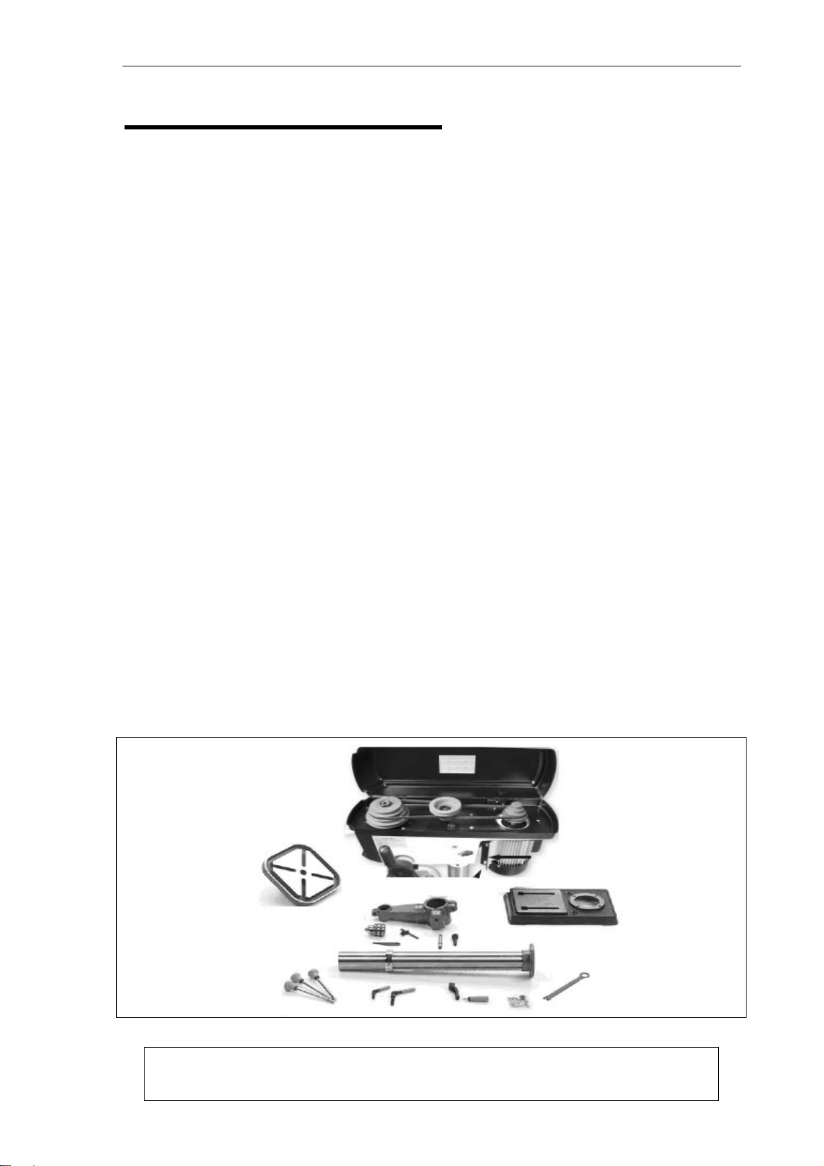
After all the parts have been removed from the carton, you should have:
• Headstock
• Table Assembly
• Base
• Column Assembly
• Drill Chuck and Key
• Drift Key
• Hex Bolts, M10 x 25 or 40 (4)
In the event that any nonproprietary parts are missing (e.g. a nut or a washer), we would
be glad to replace them, or, for the sake of expediency, replacements can be obtained at
your local hardware store.
Figure 2A
DRILL PRESS MANUAL
We reserve the right of the amendment addition and deletion of the
specifications, explanatory wording, etc. printed in this manual
7
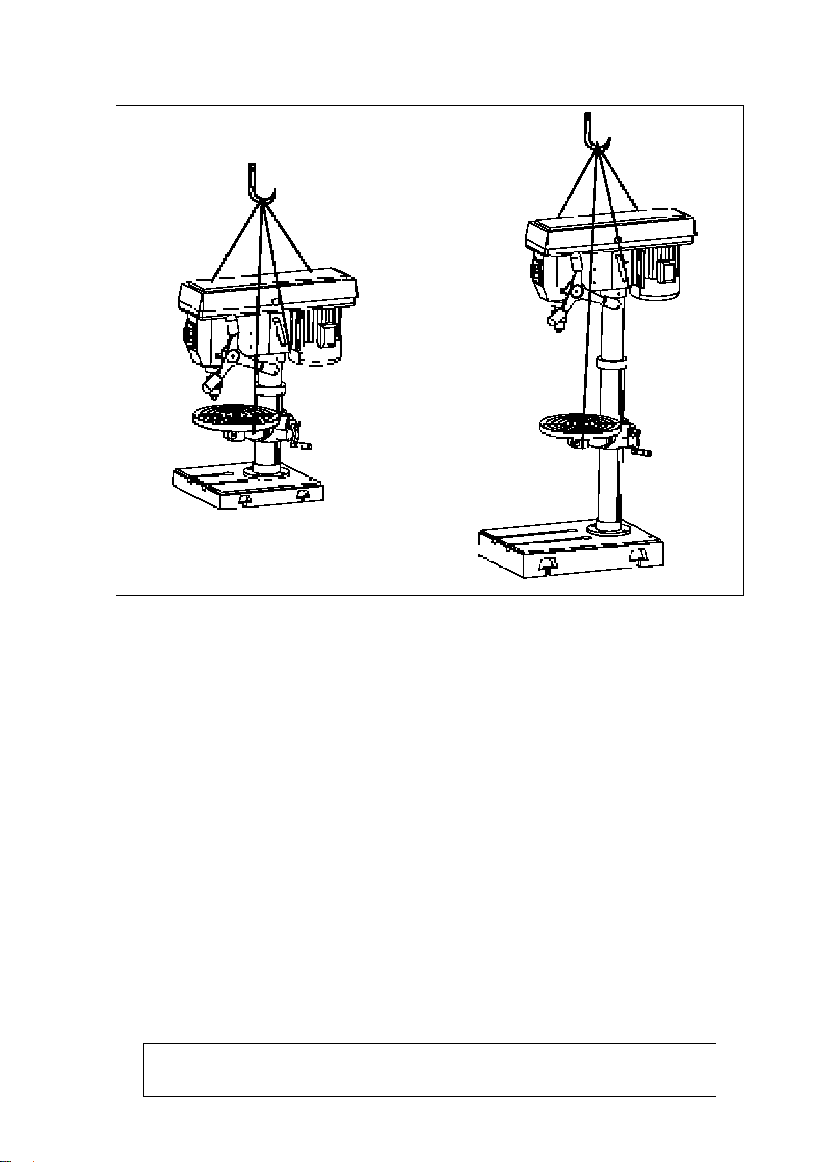
Figure2B Figure2C
Attention: Use a hoist to handle the main frame of the machine.
shown in Figure 2B & Figure 2C
Clean Up
The unpainted surfaces are coated with a waxy oil to protect them from corrosion during
shipment. Remove this protective coating with a solvent cleaner or citrus-based degreaser .
Avoid chlorine-based solvents as they may damage painted surfaces should they come in
contact. Always follow the usage instructions on the product you choose for clean up.
Site Considerations
FLOOR LOAD
Your drill press represents a moderate weight load in a small footprint. Most commercial
or home shop floors should be sufficient to carry the weight of the drill press. If you
question the strength of your floor, you can opt to reinforce it. Ensure that the stand or
bench you use with the drill press is capable of supporting the machine.

DRILL PRESS MANUAL
We reserve the right of the amendment addition and deletion of the
specifications, explanatory wording, etc. printed in this manual
8
WORKING CLEARANCES
Working clearances can be thought of as the distances between machines and obstacles
that allow safe operation of every machine without limitation. Consider existing and
anticipated machine needs, size of material to be processed through each machine, and
space for auxiliary stands and/or work tables. Also consider the relative position of each
machine to one another for efficient material handling. Be sure to allow yourself sufficient
room to safely run your machines in any foreseeable operation.
LIGHTING AND OUTLETS
Lighting should be bright enough to eliminate shadow and prevent eye strain. Electrical
circuits should be dedicated or large enough to handle combined motor amp loads. Outlets
should be located near each machine so power or extension cords are not obstructing
high-traffic areas. Be sure to observe local electrical codes for proper installation of new
lighting, outlets, or circuits.
3: ASSEMBLY
Beginning Assembly
Most of your Drill Press has been assembled at the factory, but some parts must be
assembled or installed after delivery. We have organized the assembly process into steps.
Please follow along in the order presented here.
Column/Base
Drill press must be secured to the floor using anchor bolts, or the base should be secured
to a piece of plywood.
1. Unplug machine before assembly.
2. Secure the base to the floor using the appropriate anchor bolts.
3. Place the column on the base and line up the mounting holes. Insert and tighten the
M10-1.5 hex head bolts with a wrench.
Table Support
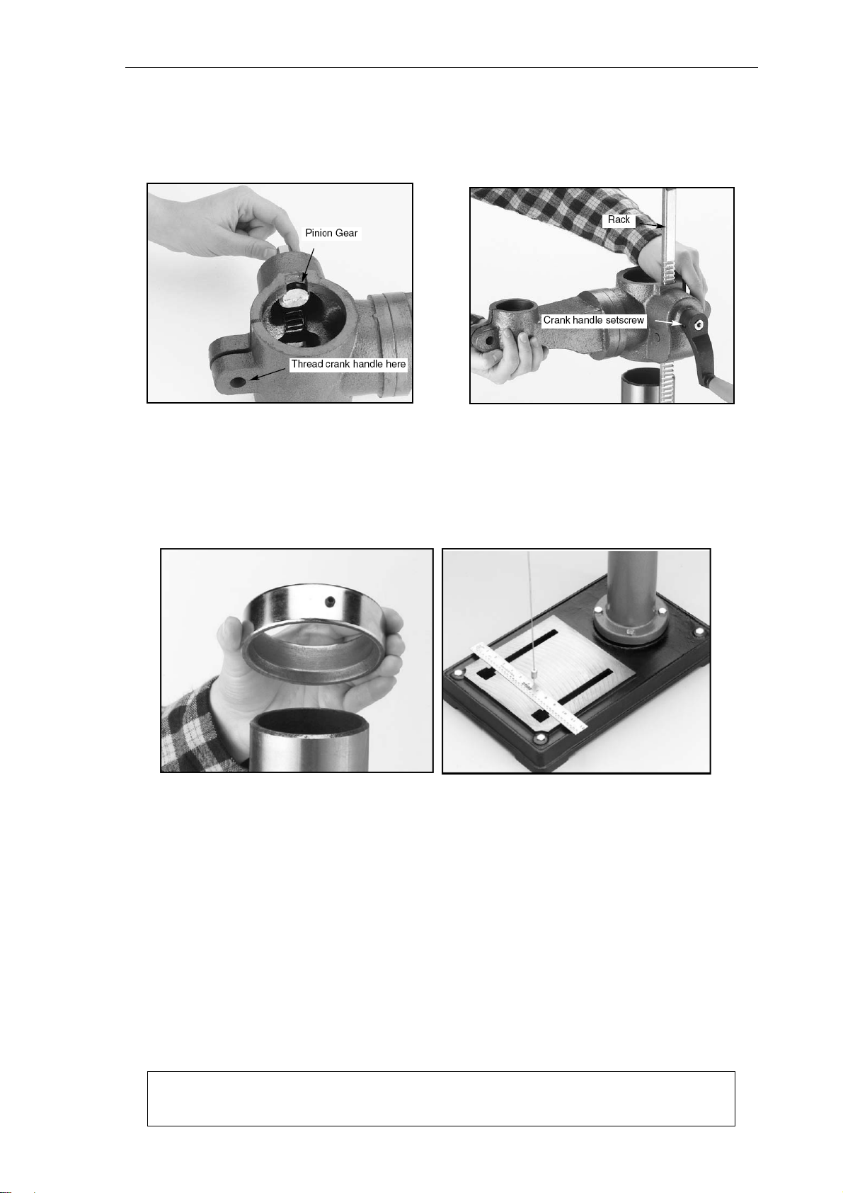
1. Thread the 12mm table lock handle 3 turns into the table support bracket as shown in
Figure 3.
2. Insert the pinion gear into the hole on the side of the table support bracket from the
inside, starting with the pinion shaft as shown in Figure 3. Align setscrew in crank
handle with flat on pinion gear shaft and secure using the 3mm Allen® wrench provided
as shown in Figure 4.
3. Examine the rack and note that the gear teeth extend farther on one end than the other.
The end of the rack where the gear teeth are closest to the end should be positioned
down. Insert the rack into the table support bracket and align it with the pocket as
shown in Figure 4. The gear teeth on the rack must also face out.
DRILL PRESS MANUAL
We reserve the right of the amendment addition and deletion of the
specifications, explanatory wording, etc. printed in this manual
9
4. Slide the table support bracket onto the column while holding the rack in place. Allow
the bracket to go down until the bottom of the rack contacts the shoulder on the column
support as shown in Figure 4. Secure the table support bracket with the lock handle.
Figure3 Figure4
5. Slide the column ring onto the column with the inside bevel in the down position as
shown in Figure 5. Adjust the ring until the tip of the rack fits inside the bevel. Tighten
the setscrew on the ring.
Figure5 Figure6
Headstock
1. There is a pocket in the bottom of the headstock for the column to be placed. Seek
assistance to help position the headstock over the column. Allow the headstock to slide
down until it stops (approximately 4").
2. Position the headstock directly over the base by using a plumb bob. Use a measuring
tape or ruler across the drill press base to find its center. Suspend the plumb line from
the center of the headstock label and lower the bob until it is near the tape/ruler as
shown in Figure 6. Adjust headstock from side to side until the tip is equidistant from
both the left and right sides.
3. Tighten the two head Locking screws shown in Figure 7 to secure headstock to the

DRILL PRESS MANUAL
We reserve the right of the amendment addition and deletion of the
specifications, explanatory wording, etc. printed in this manual
10
column.
Figure7
Handles
Three handles are supplied with the drill press. Thread them into the handle hub.
Installing Light Bulb
The drill press has a light socket that utilizes standard sized 40watt bulbs. Before installing
a light bulb, unplug the drill press. Secure bulb in opening behind the spindle.
Use only bulbs that are “safety coated” and shatter resistant. The bulb will be
exposed at the bottom of the head casting which helps with illumination. Impacts
with a bulb not “safety coated” may shatter, exposing the electrical filaments and
creating an electrical shock hazard.
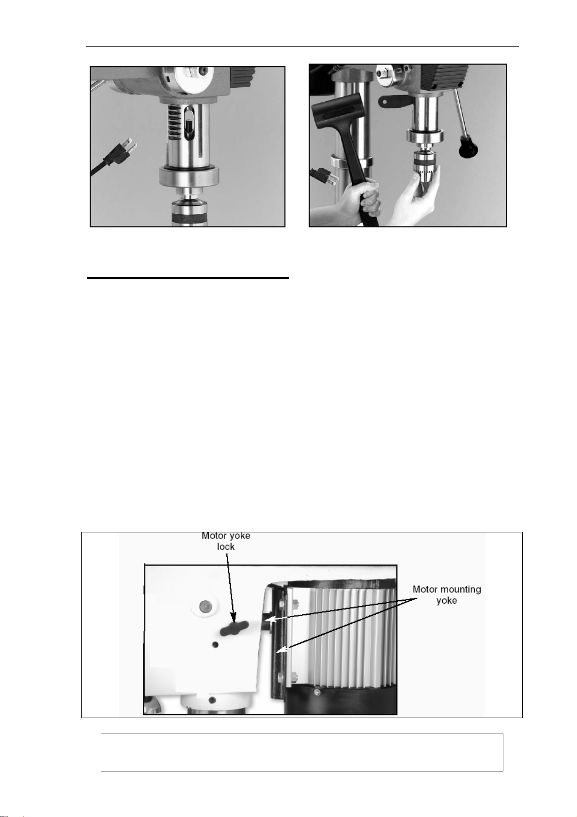
Drill Chuck and Arbor
Figure8 Figure9

DRILL PRESS MANUAL
We reserve the right of the amendment addition and deletion of the
specifications, explanatory wording, etc. printed in this manual
11
The drill chuck attaches to the drill spindle by means of a drill chuck arbor. Matched tapers
on the arbor and back of the chuck create an almost permanent assembly when properly
joined. Figure8 To assemble the drill chuck and mount it to the spindle, carefully follow
the instructions below:
1. The drill chuck, arbor and spindle socket must be thoroughly cleaned and dried before
assembly. It is recommended that mineral spirits be used for this task. Refer to the
safety warnings on the container of the mineral spirits. Failure to clean the mating
surfaces may result in separation and an unsafe condition. Separation is usually
caused by oil or grease on the taper.
2. Use the provided chuck key to adjust the jaws of the chuck until they are well inside the
drill chuck body.
3. Place the drill chuck on a workbench face down. The arbor has a short taper and a long
taper. Place the short taper into the socket in the back of the drill chuck and tap with a
rubber or wooden mallet as shown in Figure 9. If the chuck fails to remain secure on
the arbor, repeat step 1 and 2.
4. Slide the arbor into the spindle socket while slowly rotating drill chuck. The socket has
a rectangular pocket in which the tang (or flat portion of the arbor) fits into. Once the
tang is oriented correctly the drill chuck will not rotate without turning the spindle.
5. Tap the end of the drill chuck with a rubber or wooden mallet to seat it as shown in
Figure 10.
Figure 10
Arbor Removal
A drift key is included to aid in the drill chuck arbor removal.
1. Rotate the spindle handles until the slot is exposed in the side of the quill.
2. Rotate the spindle until the inner slot is aligned with the outer as shown in Figure 11.
You will see through the spindle when the slot is properly aligned.
3. Insert the drift key into the slot and allow the quill to rise, trapping the drift key. Hold the
drill chuck with one hand and tap on the drift key with a hammer as shown in Figure 12.
DRILL PRESS MANUAL
We reserve the right of the amendment addition and deletion of the
specifications, explanatory wording, etc. printed in this manual
12
Figure11 Figure12
4: ADJUSTMENTS
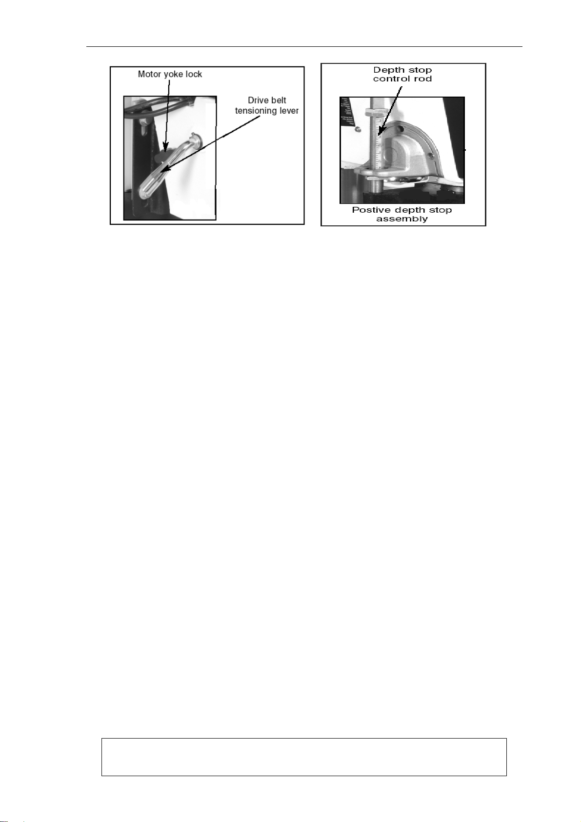
Speed Changes
Unplug the drill press before changing speeds. The drill press has 12 speeds.
There is a speed chart located under the belt guard. Refer to the chart while reading these
instructions.
1. Loosen the belt tension lock knobs on both sides of the headstock by turning
counterclockwise as shown in Figure 13.
2. The motor should be free to move. Rotate the belt tension lever counterclockwise to
take tension off the V-belts as shown in Figure 14.
3. Locate the desired speed on the chart and move the V-belts to the desired V-grooves
on the motor, idler and spindle pulleys.
4. Rotate the belt tension lever until the belts are tight. Tighten both lock knobs.
5. Close the cover.
Figure 13
DRILL PRESS MANUAL
We reserve the right of the amendment addition and deletion of the
specifications, explanatory wording, etc. printed in this manual
13
Figure14 Figure 15.
Depth Stop
Your drill press comes with a depth stop adjustment for use when drilling.
This is a combination of a cast angle bracket & cover, which fits in a housing machined in
the drillhead, (it mounts the bearing pocket for the end of the splined feed shaft and the
return spring), the ‘angle arm’ of the bracket protudes out from the drillhead parallel with
the base. There is a clearance hole bored through this arm. There is a round plate casting
with a triangular extrusion clamped around the outer sleeve of the quill. Within the apex of
this triangle a threaded hole mounts the depth stop control rod, which also feeds up
through the clearance hole in the angle arm bracket. This rod is originally threaded, which
allows it to be screwed through the hole in the plate and secured in position with a lock nut.
The greater part of the rod over the top of the mounting plate has been milled flat (less than
radius depth) to enable a scale decal to be fitted. A nut is fitted over to the depth stop rod
below the angle arm bracket (to control the ‘lift’ of the quill) and a nut and a lock nut fitted
above the angle arm bracket to limit the ‘plunge’. The graduated scale can be read over the
top of the angle arm bracket and will allow the depth of the drill plunge to be measured, or
set. Which as shown in Figure 15.
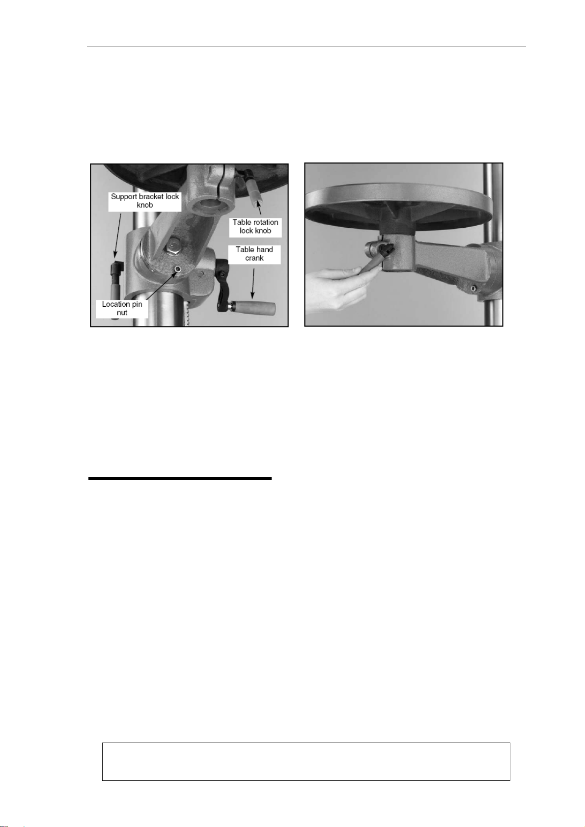
Table Adjustment
The table can be adjusted for height, rotation and angle.
1. Loosen the support bracket lock knob. Turn the table hand crank to lift or lower the
table as shown in Figure 16.
2. Always lock the support bracket in place before operating the machine.
Adjust rotation:
1. Loosen the lock handle located under the table as shown in Figure 17. Rotate the
table the desired amount.
2. Always lock the table rotation in place before operating the machine.
Adjust angle:
DRILL PRESS MANUAL
We reserve the right of the amendment addition and deletion of the
specifications, explanatory wording, etc. printed in this manual
14
1. Turn the nut indicated by the arrow in Figure 16, in a clockwise direction. This will draw
the location pin out of the casting. Once loose, pull the pin and nut out, and set it in a
safe place until needed.
2. Loosen the large bolt in the center of the support bracket.
3. Rotate the bracket to the desired angle. Use the scale on the side of the bracket or a
protractor to set the angle. Lock in place by tightening the bolt.
Figure16 Figure17
When repositioning the table to 0° position, loosen the large bolt in the center of the
support casting. Rotate the support casting until the degree scale reads 0°. Carefully tap
the location pin back into the hole from which it came until it stops. Unscrew the nut on the
location pin until it is flush with the end of the threads. This will protect the threads when
you tap it into place with a hammer. Turn the nut clockwise until it is snug against the
casting and then tighten the large bolt in the center. The table is now set to the factory
pre-set angle.
5: OPERATIONS
Test Run
Once assembly is complete and adjustments are done to your satisfaction, you are ready
to test run the machine.
Turn on the power supply at the main panel. Flip the START button. Make sure that your
finger is poised on the paddle switch, just in case there is a problem. The drill press should
run smoothly, with little or no vibration or rubbing noises. Strange or unnatural noises
should be investigated and corrected before operating the machine further.
If you cannot easily locate the source of an unusual noise or vibration, contact our service
department for help.
Drill Bit Changes
Make sure to secure the bit firmly in place. When changing bits, proceed as follows:
1. Disconnect the machine from power source.

DRILL PRESS MANUAL
We reserve the right of the amendment addition and deletion of the
specifications, explanatory wording, etc. printed in this manual
15
2. Open the chuck wide enough to accept a new bit.
3. Install the bit so the chuck jaws will grab as much of the bit shank as it can. Do not
allow the chuck to grab the fluted body of the drill bit. Make sure small drill bits do not
get trapped between the edges of two jaws.
4. Tighten the chuck with the chuck key using any of the three key end locations.
5. Remove the chuck key and reconnect power source.
6. Reverse steps to remove drill bit.
6: MAINTENANCE
General
Regular periodic maintenance on your drill press will ensure its optimum performance.
Make a habit of inspecting your machine each time you use it. Check for the following
conditions and repair or replace when necessary:
1. Loose mounting bolts.
2. Worn switch.
3. Worn or damaged cords and plugs.
4. Damaged V-belt.
5. Any other condition that could hamper the safe operation of this machine.
Tables
The nonpainted surfaces on the drill pressshould be protected against rust and pitting.
Wiping the machine clean after every use ensures that wood dust will not trap moisture
against bare metal surfaces.
Some woodworkers recommend using automotive paste wax on exposed steel and cast
iron surfaces. The wax provides a layer of protection, as well as reducing friction between
lumber and the table, making cuts faster and smoother. Avoid waxes that contain silicone
or other synthetic ingredients. These materials can find their way into lumber that is being
worked, and can make staining and finishing difficult. If you use paste wax, make sure that
it is 100% Carnauba wax.
Lubrication
Inspect regularly for tension and wear. Check pulleys to ensure that they are properly
aligned. See pulley/V-belt sections for proper tension and pulley alignment procedures.
V-Belt

DRILL PRESS MANUAL
We reserve the right of the amendment addition and deletion of the
specifications, explanatory wording, etc. printed in this manual
16
Since all bearings are shielded and permanently lubricated, simply leave them alone until
they need to be replaced. Do not lubricate them.
7: TECHICAL DATA
Model Bench ZQJ4116K ZQJ4119K
Floor
Spindle Taper MT2 MT2
Chuck (mm) 3-16mm 3-16mm
Spindle Travel 80mm 80mm
Swing(mm) 330mm/13” 356mm/14”
Speeds 12s (16s) 12s (16s)
Height Bench 990mm 1000mm
Floor
Motor See Nameplate See Nameplate
N.W./G.W. Bench 63/67kgs 82/86
Floor
WIRING DIAGRAM FOR ZQJ4116K

DRILL PRESS MANUAL
We reserve the right of the amendment addition and deletion of the
specifications, explanatory wording, etc. printed in this manual
17
WIRING DIAGRAM FOR ZQJ4119K

DRILL PRESS MANUAL
We reserve the right of the amendment addition and deletion of the
specifications, explanatory wording, etc. printed in this manual
18
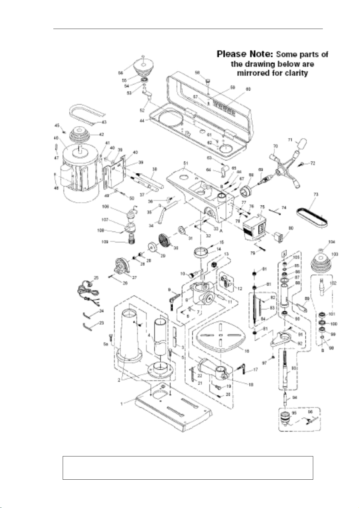
8:PARTS LISTS & EXPODED VIEWS
1.ZQJ4116K

DRILL PRESS MANUAL
We reserve the right of the amendment addition and deletion of the
specifications, explanatory wording, etc. printed in this manual
19
PARTS LIST: ZQJ4116K DRILL PRESS
NO. DESCRIPTION Q’TY NO. DESCRIPTION Q’TY
1 BASE 1 53
C-CLIP 1
2 COLUMN SHOULDER 1 54
BALL BEARING 1
3 RACK 1 55
CENTER PULLE
Y
1
4 COLUMN 1 56
C-CLIP 1
5 HEX BOLT 4 57
SCREW 1
6 SCREW 2 58
KNOB 1
7 MARK 1 59
WASHER 1
8 TABLE BRACKET 1 60
SPEED CHART LABEL 1
9 CLAMP BOLT 1 61
SCREW 4
10 WORM GEAR 1 62
WASHER 4
11 SHAFT 1 63
HEX BOLT 1
12 HANDLE 1 64
SHIFTER 1
13 GEAR 1 65
SET SCREW 1
14 RACK RING 4 66
SET SCREW 1
15 SET SCREW 1 67
SET SCREW 2
16 TABLE 1 68
DEPTH RING 1
17 TABLE BOLT 1 69
FEED SHAFT 1
18 TABLE ARM BRACKET 1 70
HANDLE 1
19 HEX BOLT 2 71
HANDLE COVER 1
20 PIN 1 72
CAP BOLT 1
21 MARK 1 73
V
-BELT 1
22 SCREW 2 74
SCREW 2
23 WRENCH 5mm 1 75
SWITCH BOX 1
24 WRENCH 3mm 1 76
SCREW 2
25 POWER CORD 1 77
WASHER 2
26 SCREW 3 78
WASHER 1
27 COVER 1 79
SCREW 2
28 NUT 2 80
SWITCH 1
29 SPRING CAP 1 81
NUT 3
30 TORSION SPRING 1 82
SCREW 2
31 SPRING COVER 1 83
SCALE 1
32 NUT 1 84
SCALE BASE 1
33 SCREW SPECIAL SET 1 85
C--CLIP 1
34 SHIFTER BAR 1 86
BALL BEARING 1
35 C-CLIP 1 87
RUBBER WASHER 1
36 SLIDE BAR BOLT 2 88
SPINDLE SLEEVE 1
37 SLIDE BAR 1 89
WEDGE 1
38 SLIDE BAR 1 90
BALL BEARING 1
39 WASHER 2 91
CAP BOLT 1
40 MOTOR BASE 2 92
PLATE 1
41 NUT 2 93
SPINDLE 1
42 MOTOR PULLEY 1 94
A
RBOR 1
43
V
-BELT 1 95
CHUCK 1
44 PULLEY COVER 1 96
CHUCK KEY 1
45 SET SCREW 1 97
NUT 1
46 MOTOR 1 98
C--CLIP 1
47 KEY 1 99
BALL BEARING 1
48 NUT 4 100
SPACER 1
49 WASHER 4 101
BALL BEARING 1
50 HEX BOLT 4 102
INSERT PULLEY 1
51 BODY 1 103
SPINDLE PULLE
Y
52 CENTER SHAFT 1 104
PULLEY NUT 1
DRILL PRESS MANUAL
We reserve the right of the amendment addition and deletion of the
specifications, explanatory wording, etc. printed in this manual
20
2. ZQJ4119K
This manual suits for next models
3
Table of contents
Other Garrick Machine Tools Power Tools manuals


