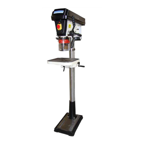
Garrick Machine Tools DP25 User manual

INDUSTRIAL PEDESTAL DRILL
PRESS
Model’s DP25 & DP32
INSTRUCTION MANUAL
For your safety, read all instructions carefully.
ISO-9001:2008 Certied

DRILLPRESS MANUAL
Wereservetherightoftheamend
mentadditionanddeletionofthe
specifications, explanatorywording, etc.printedinthismanual
2
WARNING
Somedustcreatedbypowersanding,sawing,grinding,drilling,and
otherconstructionactivitiescontainschemicalsknowntotheStateof
Californiatocausecancer,birthdefectsor other reproductiveharm.
Someexamplesof thesechemicalsare:
Leadfromlead-based paints.
Crystalline silicafrombricks, cement, andothermasonryproducts.
Arsenicandchromiumfromchemicallytreated lumber.
Yourriskfromtheseexposuresvaries,dependingonhowoftenyou do
thistypeofwork.Toreduceyourexposure tothesechemicals:workin
awell ventilated area,andworkwithapprovedsafetyequipment, such
asthosedustmasksthatarespeciallydesignedtofilterout
microscopicparticles.
PDF 件使用 "pdfFactory Pro" 试用版本创建 www.fineprint.cn

DRILLPRESS MANUAL
Wereservetherightoftheamend
mentadditionanddeletionofthe
specifications, explanatorywording, etc.printedinthismanual
3
TableOfContents PAGE
1. SAFETY
SAFETYRULES FORALL TOOLS............................……......................................…4
ADDITIONALSAFETYINSTRUCTIONSFORDRILL PRESS .......................... .5
2.INTRODUCTION
UNPACKING.............................................…........................................................…………...7
PIECEINVENTORY..............................…..................................................................7
CLEANUP.................................................………….............................................................8
SITECONSIDERATIONS................….....……..….............................................................8
3.ASSEMBLY
BEGINNINGASSEMBLY.................………......................................................................9
COLUMN/BASE.................................…….....................................................................9
TABLESUPPORT.............................…………....................................................................9
HEADSTOCK.....................................……………..................................................................11
HANDLES .............................................………………...............................................................11
INSTALLINGLIGHTBULB........................………………..........................................................11
DRILLCHUCKAND ARBOR................…………...............................................................11
ARBORREMOVAL................................……………..............................................................12
4.ADJUSTMENTS
SPEEDCHANGES ...............................…………...............................................................12
DEPTHSTOP.........................................……………...............................................................13
TABLEADJUSTMENTS...........................…………….............................................................14
5. OPERATIONS
TESTRUN....................................................…………….........................................................15
DRILL BITCHANGES.....................................……………….....................................................15
6. MAINTENANCE
GENERAL.......................................…….....................................................................16
TABLES.............................................……...................................................................16
LUBRICATION..................................……....................................................................16
V-BELT............................................…......................................................................16
7. TECHICALDATA .......……………….........................................................................16
8. PARTSLISTS&EXPODEDVIEWS .………..............................................17--18
PDF 件使用 "pdfFactory Pro" 试用版本创建 www.fineprint.cn

DRILLPRESS MANUAL
Wereservetherightoftheamend
mentadditionanddeletionofthe
specifications, explanatorywording, etc.printedinthismanual
4
1:SAFETY
SafetyInstructionsForPowerTools
For YourOwn SafetyRead Instruction
Manual BeforeOperatingThisEquipment
. Keepworkarea clear. Cluttered areasandbenchesinviteinjuries.
2. Considerworkareaenvironment.Donotexposetoolstorain.Donotusetoolsin
damporwetlocation.Keepworkareawell lit.Donotusetoolsinthepresenceof
flammableliquidsorgases.
3. Guardagainstelectricshock.Avoidbodycontactwithearthedorgrounded
surfaces.(e.g.pipes,radiator,ranges,refrigerators).
4. Keepotherperson away.Donotletpersons,especiallychildren,involved inthework
touchthetoolortheextension cordand keepthemawayfromworkarea.
5. Storeidletools.Whennotisuse,toolsshouldbestoredinadrylockedupplace,out
ofreachof children.
6. Donotforcethetool.Itwill do thejobbetterandsaferattherateforwhichitwas
intended.
7. Usetherighttool.Donotforcesmall toolstodo thejobofaheavy dutytool.Donot
usetoolsforpurposesnotintended,forexampledonotusecircularsawstocuttree
limbsorlogs.
8. Dress properly.Donotwearlooseclothingorjewellery,theycanbecaughtinmoving
parts.Non-skidfootwearisrecommended when working outdoors.Wearprotective
haircoveringtocontainlonghair.
9. Useprotectiveequipment.Usesafetyglass.Alsousefaceordustmask ifcutting
operationsisdusty.
0. Connectdustextractionequipment.Ifdevicesareprovided forconnectionofdust
extractionand collectionfacilitiesensurethereareconnectedandpropertyused.
. Donotabusethecord.Neveryankthe cordtodisconnectit fromthesocket.Keepthe
cordawayfromhear, oil and sharpedges.
2. Securework.Wherepossibleuseclampsoravicetoholdthework.itissaferthan
usingyourhands.
3. Donotoverreach. Keep properfootingandbalanceat all times.
4. Maintaintoolswithcare. Keep toolssharpandcleanforbetterandsaferperformance.
Followinstruction forlubricatingandchanging accessories.Inspecttoolcords
periodicallyandifdamagedhavethemrepairedbyanauthorizedservicefacility.
Inspectextensioncordsperiodicallyandreplaceifdamaged.Keep handlesdry,clean
andfreefromoil andgrease.
5. Disconnecttool,Whennotinuse beforeservicing and whenchanging accessories
suchasblades, bitandcutters disconnecttoolsfromthepowersupply.
6. Removeadjusting keys andwrenches. Form thehabitofcheckingtoseethatkeysand
adjustingwrenchesareremovedfromthetoolbeforeturningiton.
7. Avoidunintentionalstarting. Ensureswitchis “off”positionwhen plugging in.
8. Useoutdoorextension leads.When toolisused outdooronlyextension cordsintended
foroutdooruseandsomarked.
9. Stayalert. Watchwhatyouaredoing,usecommon senseanddonotoperatetool
whenyouaretired.
20. Check damaged parts. Beforefurtheruseof the tool,itshouldbecarefullychecked to
determine thatitwill operateproperlyand perform itsintendedfunction.Check for
PDF 件使用 "pdfFactory Pro" 试用版本创建 www.fineprint.cn

DRILLPRESS MANUAL
Wereservetherightoftheamend
mentadditionanddeletionofthe
specifications, explanatorywording, etc.printedinthismanual
5
alignmentofmovingparts,breakage ofparts,mountingandanyotherconditionthat
mayaffectitsoperation.Aguardorotherpartthatisdamagedshouldbeproperly
repairedorreplacedbyanauthorisedservicecentreunless otherwiseindicatedinthis
instruction manual.Havedefectiveswitchesreplaced byan authorised servicecenter.
Donotusetoolifswitchdoesnot turnitonandoff.
2 . Warning:theuseofanyaccessoryorattachmentotherthananrecommendedinthis
instruction manualmaypresentarisk ofpersonalinjury.
22. Haveyourtoolrepairedbyaqualifiedperson.Thiselectrictoolcomlieswiththe
relevantsafetyrules.Repairsshouldonlybecarried outbyqualified personsusing
originalspareparts, otherwisethismayresult inconsiderabledangertotheuser.
23. Savetheseinstructions.
Additional SafetyInstructionsForDrill Presses
1.ALWAYS OPERATEYOURDRILL PRESSATSPEEDS thatareappropriateforthe
drill bit sizeand thematerialthat youaredrilling.
2.FEEDTHEDRILL BITEVENLYINTO THEWORKPIECE. Back thebitoutofdeep
holesandclearthechipswithabrushafteryouhaveturnedthemachineoff.
3.MAKESURETHEDRILL BITYOUAREUSING ISTIGHTENEDPROPERLY. Use
onlyround,hexortriangularshankdrill bits.
4.NEVERDO MAINTENANCEORCHANGESPEEDSWITHTHISMACHINE
PLUGGEDIN.
5.NEVERUSE TOOLSTHATAREINPOORCONDITION. Cutting toolsthataredull or
damagedaredifficult tocontrolandmaycauseseriousinjury.
6.NEVERDRILL SHEETMETALUNLESS ITISCLAMPEDSECURELYTOTHE
TABLE.
7.WORK SHOULDBEPOSITIONEDINSUCHAWAYASTOAVOIDDRILLING INTO
THETABLE.
8.AFACESHIELDUSEDWITHSAFETYGLASSES ISRECOMMENDED.
9.ALWAYS CLAMPWORKPIECESECURELYTOTABLEBEFOREDRILLING. Never
holdaworkpiecebyhandwhiledrilling.
10.IFATANYTIMEYOUAREEXPERIENCING DIFFICULTIES performingthe intended
operation,stopusingthe machine! Thencontactourservicedepartmentoraska
qualifiedexperthowthe operationshouldbeperformed.
11.REMOVE ADJUSTING KEYSAND WRENCHES. Beforeturningthemachine on,
makeitahabittocheck thatall adjustingkeys and wrencheshavebeenremoved.
12.HABITS—GOODANDBAD—AREHARD TO BREAK. Developgood habitsinyour
shopandsafetywill becomesecond-naturetoyou.
PDF 件使用 "pdfFactory Pro" 试用版本创建 www.fineprint.cn

DRILLPRESS MANUAL
Wereservetherightoftheamend
mentadditionanddeletionofthe
specifications, explanatorywording, etc.printedinthismanual
6
2:INTRODUCTION
Unpacking
Ifmoving thismachineup ordownstairs, themachinemustbedismantledand
movedinsmallerpieces. Make surefloorand stairstructuresarecapableof
supporting thecombinedweightofthemachinepartsand thepeoplemoving them
The Drill Pressisshippedfromthemanufacturerinacarefullypackedcarton. If you
discoverthemachine isdamagedafteryou’vesignedfordelivery, immediatelycall
CustomerServiceforadvice.
When youarecompletelysatisfied withthecondition ofyourshipment, you should
inventoryitsparts.
PieceInventory
Afullpartslistand breakdowncanbefound towardtheendofthismanual. For
easierassembly, ortoidentifyspecificparts, pleaserefertothedetailedillustrations
attheend ofthemanual.
Afterall the partshavebeenremovedfromthe carton, youshouldhave:
Headstock
TableAssembly
Base
ColumnAssembly
Drill Chuck andKey
DriftKey
HexBolts,M10 x25 or40(4)
Intheevent thatanynonproprietarypartsaremissing (e.g. anutorawasher), wewould
be gladtoreplacethem,or,forthesakeofexpediency,replacementscan beobtainedat
yourlocalhardwarestore.
Figure2A
PDF 件使用 "pdfFactory Pro" 试用版本创建 www.fineprint.cn

DRILLPRESS MANUAL
Wereservetherightoftheamend
mentadditionanddeletionofthe
specifications, explanatorywording, etc.printedinthismanual
7
Figure2BFigure2C
Attention:Use ahoist tohandlethemainframeofthemachine.
shownin Figure2B& Figure2C
Clean Up
The unpainted surfacesarecoatedwithawaxyoiltoprotectthemfromcorrosion during
shipment.Removethisprotectivecoatingwithasolventcleanerorcitrus-baseddegreaser.
Avoidchlorine-based solventsastheymaydamagepaintedsurfacesshouldtheycomein
contact. Always followtheusageinstructionsontheproduct youchooseforcleanup.
SiteConsiderations
FLOORLOAD
Yourdrill pressrepresentsamoderateweight loadinasmall footprint. Mostcommercial
orhomeshopfloorsshouldbesufficienttocarrythe weightofthedrill press. Ifyou
questionthestrengthofyourfloor, youcanopt toreinforceit.Ensurethatthestandor
benchyouusewiththedrill pressiscapableof supportingthemachine.
PDF 件使用 "pdfFactory Pro" 试用版本创建 www.fineprint.cn

DRILLPRESS MANUAL
Wereservetherightoftheamend
mentadditionanddeletionofthe
specifications, explanatorywording, etc.printedinthismanual
8
WORKING CLEARANCES
Workingclearancescan bethoughtofasthe distancesbetweenmachinesandobstacles
that allowsafeoperationof everymachinewithoutlimitation. Considerexistingand
anticipatedmachineneeds,sizeofmaterialtobeprocessedthrougheachmachine,and
spaceforauxiliarystandsand/orworktables.Alsoconsidertherelativepositionof each
machinetooneanotherforefficient materialhandling.Besuretoallowyourselfsufficient
roomtosafelyrunyourmachinesinanyforeseeableoperation.
LIGHTING AND OUTLETS
Lightingshouldbe brightenough toeliminateshadowandpreventeyestrain.Electrical
circuitsshouldbededicatedorlargeenoughtohandlecombinedmotoramploads.Outlets
shouldbelocatedneareachmachinesopowerorextension cordsarenotobstructing
high-trafficareas.Besuretoobservelocalelectricalcodesforproperinstallationofnew
lighting,outlets, orcircuits.
3:ASSEMBLY
BeginningAssembly
Most ofyourDrill Presshasbeen assembledat thefactory, but somepartsmust be
assembledorinstalled afterdelivery. Wehaveorganizedtheassemblyprocess intosteps.
Pleasefollowalong intheorderpresented here.
Column/Base
Drill press mustbesecuredtothefloorusinganchorbolts,orthe baseshouldbesecured
toapieceof plywood.
1.Unplugmachinebeforeassembly.
2.Securethebasetothefloorusingtheappropriateanchorbolts.
3.Placethecolumnonthebaseand line upthemountingholes. Insertand tightenthe
M10-1.5hexheadboltswithawrench.
TableSupport
1.Threadthe12mm tablelock handle3turnsintothetablesupportbracketasshownin
Figure3.
2.Insert thepiniongearintotheholeontheside of the tablesupportbracket fromthe
inside, startingwiththepinionshaft asshownin Figure3. Align setscrewincrank
handlewithflatonpiniongearshaftandsecureusing the3mm Allen®wrenchprovided
asshownin Figure4.
3.Examinetherackandnotethatthegearteethextendfartherononeendthantheother.
The endoftherack wherethe gearteethareclosest totheendshouldbepositioned
down. Inserttherack intothetablesupportbracket and alignit withthepocket as
shownin Figure4.Thegearteethontherack must alsofaceout.
PDF 件使用 "pdfFactory Pro" 试用版本创建 www.fineprint.cn

DRILLPRESS MANUAL
Wereservetherightoftheamend
mentadditionanddeletionofthe
specifications, explanatorywording, etc.printedinthismanual
9
4.Slide thetablesupportbracketontothecolumnwhileholding therackinplace.Allow
thebrackettogodownuntil the bottomof therackcontactsthe shoulderonthecolumn
supportasshownin Figure4. Securethetablesupport bracket withthelock handle.
Figure 3Figure 4
5.Slide thecolumnring ontothecolumnwiththeinside bevelinthedownposition as
shownin Figure5.Adjusttheringuntil thetipof the rack fitsinsidethebevel. Tighten
thesetscrewon thering.
Figure5Figure6
Headstock
1. Thereisapocket inthebottomoftheheadstock forthecolumntobeplaced.Seek
assistancetohelppositionthe headstockoverthecolumn.Allowthe headstocktoslide
downuntil it stops(approximately4").
2. Positiontheheadstock directlyoverthebasebyusing aplumbbob.Useameasuring
tapeorruleracrossthedrill press basetofinditscenter.Suspendtheplumblinefrom
thecenterof theheadstock labelandlowerthebobuntil it isnearthetape/ruleras
shownin Figure6.Adjustheadstock fromsidetoside until thetipisequidistant from
boththeleft andrightsides.
3. Tighten thetwohead Lockingscrewsshownin Figure7 tosecureheadstock tothe
PDF 件使用 "pdfFactory Pro" 试用版本创建 www.fineprint.cn

DRILLPRESS MANUAL
Wereservetherightoftheamend
mentadditionanddeletionofthe
specifications, explanatorywording, etc.printedinthismanual
10
column.
Figure7
Handles
Threehandlesaresuppliedwiththe drill press. Threadthemintothehandlehub.
Installing LightBulb
The drill presshasalight socketthatutilizesstandardsized 40wattbulbs.Beforeinstalling
alightbulb, unplugthedrill press.Securebulbinopeningbehindthe spindle.
Useonlybulbsthatare “safetycoated”and shatterresistant. Thebulbwillbe
exposedatthebottomoftheheadcasting whichhelpswithillumination. Impacts
withabulbnot “safetycoated”mayshatter, exposing theelectricalfilamentsand
creating anelectricalshock hazard.
Drill Chuck and Arbor
Figure8 Figure9
PDF 件使用 "pdfFactory Pro" 试用版本创建 www.fineprint.cn

DRILLPRESS MANUAL
Wereservetherightoftheamend
mentadditionanddeletionofthe
specifications, explanatorywording, etc.printedinthismanual
11
The drill chuck attachestothedrill spindlebymeansof adrill chuck arbor. Matched tapers
on thearborandback of thechuckcreateanalmost permanent assemblywhen properly
joined.Figure8 Toassemblethe drill chuck andmount ittothespindle, carefullyfollow
theinstructionsbelow:
1.The drill chuck,arborandspindlesocket mustbe thoroughlycleanedanddriedbefore
assembly. It isrecommended that mineralspiritsbeusedforthistask. Refertothe
safetywarningsonthecontainerof themineralspirits. Failuretocleanthemating
surfacesmayresultinseparation and anunsafecondition. Separation isusually
causedbyoil orgreaseonthe taper.
2.Usethe providedchuck keytoadjustthejawsof the chuck until theyarewell insidethe
drill chuckbody.
3.Placethedrill chuckonaworkbenchfacedown. The arborhasashort taperandalong
taper.Placethe shorttaperintothe socket inthe back of thedrill chuckand tapwitha
rubberorwoodenmalletasshownin Figure9.If the chuck failstoremainsecureon
thearbor, repeat step1and 2.
4.Slide thearborintothespindlesocket whileslowlyrotatingdrill chuck.Thesockethas
arectangularpocket inwhichthe tang (orflat portion ofthearbor) fitsinto.Oncethe
tangisorientedcorrectlythedrill chuck will not rotatewithoutturningthe spindle.
5.Tap theendof the drill chuck witharubberorwoodenmallet toseatit asshownin
Figure10.
Figure10
ArborRemoval
Adriftkeyisincluded toaidinthedrill chuck arborremoval.
1. Rotatethespindlehandlesuntil the slot isexposedinthesideofthequill.
2. Rotatethespindleuntil theinnerslot isalignedwiththe outerasshownin Figure11.
You will seethroughthespindlewhentheslotisproperlyaligned.
3. Insertthedrift keyintotheslotandallowthequill torise,trapping thedrift key. Holdthe
drill chuckwithonehandand taponthedriftkeywithahammerasshownin Figure12.
PDF 件使用 "pdfFactory Pro" 试用版本创建 www.fineprint.cn

DRILLPRESS MANUAL
Wereservetherightoftheamend
mentadditionanddeletionofthe
specifications, explanatorywording, etc.printedinthismanual
12
Figure11 Figure12
4:ADJUSTMENTS
Speed Changes
Unplug thedrillpress beforechanging speeds. Thedrill press has12speeds.
Thereisaspeedchart locatedunderthebelt guard. Refertothechart whilereadingthese
instructions.
1. Loosenthebelt tension lock knobsonbothsidesoftheheadstock byturning
counterclockwiseasshownin Figure13.
2. The motorshouldbefree tomove. Rotatethebelttensionlevercounterclockwiseto
taketensionofftheV-beltsasshownin Figure14.
3. Locatethedesiredspeedonthechart andmovethe V-beltstothedesiredV-grooves
on themotor, idlerandspindlepulleys.
4. Rotatethebelt tensionleveruntil the beltsaretight. Tightenbothlock knobs.
5. Closethecover.
Figure13
PDF 件使用 "pdfFactory Pro" 试用版本创建 www.fineprint.cn

DRILLPRESS MANUAL
Wereservetherightoftheamend
mentadditionanddeletionofthe
specifications, explanatorywording, etc.printedinthismanual
13
Figure14 Figure15.
Depth Stop
Yourdrill presscomeswithadepthstopadjustmentforusewhendrilling.
Thisisacombinationof acast anglebracket&cover, whichfitsinahousingmachined in
thedrillhead, (it mountsthebearingpocketfortheendofthe splined feedshaftandthe
returnspring), the ‘anglearm’of the bracketprotudesoutfromthedrillheadparallelwith
thebase.Thereisaclearanceholeboredthroughthisarm. Thereisaround platecasting
withatriangularextrusionclampedaroundthe outersleeveofthequill.Withintheapexof
thistriangleathreadedholemountsthe depthstopcontrolrod, whichalsofeedsup
throughthe clearanceholeintheanglearm bracket. Thisrodisoriginallythreaded, which
allowsittobescrewed throughtheholeintheplateandsecuredinpositionwithalock nut.
The greaterpartof the rod overthetopof themountingplatehasbeenmilled flat (lessthan
radiusdepth)toenableascaledecaltobefitted.Anut isfitted overtothedepthstop rod
belowtheanglearm bracket(tocontrolthe ‘lift’ofthequill)andanutandalocknutfitted
abovetheanglearm brackettolimit the ‘plunge’. The graduatedscalecanbereadoverthe
topof theanglearm bracketandwill allowthedepthofthedrill plunge tobemeasured,or
set. Whichasshownin Figure15.
TableAdjustment
The tablecanbeadjustedforheight, rotationandangle.
1. Loosenthesupport bracket lockknob. Turnthetablehand cranktoliftorlowerthe
tableasshownin Figure16.
2. Always lock the support bracket inplacebeforeoperatingthemachine.
Adjust rotation:
1. Loosenthelock handlelocatedunderthetableasshownin Figure17. Rotatethe
tablethe desired amount.
2.Always lockthe tablerotationinplacebeforeoperatingthemachine.
Adjust angle:
PDF 件使用 "pdfFactory Pro" 试用版本创建 www.fineprint.cn

DRILLPRESS MANUAL
Wereservetherightoftheamend
mentadditionanddeletionofthe
specifications, explanatorywording, etc.printedinthismanual
14
1. Turnthenut indicatedbythe arrowin Figure16,inaclockwisedirection. Thiswill draw
thelocationpinoutof thecasting.Onceloose,pullthepinandnutout,andset it ina
safeplaceuntil needed.
2.Loosenthe largebolt inthe centerofthesupport bracket.
3.Rotatethebracket tothe desired angle. Usethescaleontheside ofthebracket ora
protractortosettheangle.Lockinplacebytighteningthebolt.
Figure16Figure17
When repositioningthetableto0°position,loosen thelargeboltinthecenterof the
supportcasting. Rotatethesupport castinguntil thedegree scalereads0°. Carefullytap
thelocationpinbackintothe holefromwhichit cameuntil it stops. Unscrewthenutonthe
location pinuntil it isflushwiththeendof the threads.Thiswill protect thethreadswhen
you tapit intoplacewithahammer. Turnthenutclockwiseuntil itissnugagainstthe
castingandthentightenthelargebolt inthecenter. Thetableisnowset tothefactory
pre-setangle.
5:OPERATIONS
TestRun
Onceassemblyiscompleteandadjustmentsaredone toyoursatisfaction, youareready
totest run themachine.
Turnon thepowersupplyatthemainpanel. Flipthe STARTbutton. Makesurethatyour
fingerispoisedon thepaddleswitch, just incasethereisaproblem.Thedrill press should
run smoothly, withlittleornovibrationorrubbingnoises.Strangeorunnaturalnoises
shouldbeinvestigated andcorrected beforeoperating themachinefurther.
Ifyoucannot easilylocatethesourceofanunusualnoiseorvibration, contactourservice
departmentforhelp.
Drill BitChanges
Makesuretosecurethebit firmlyinplace.Whenchanging bits,proceedasfollows:
1. Disconnectthemachinefrompowersource.
PDF 件使用 "pdfFactory Pro" 试用版本创建 www.fineprint.cn

DRILLPRESS MANUAL
Wereservetherightoftheamend
mentadditionanddeletionofthe
specifications, explanatorywording, etc.printedinthismanual
15
2. Openthechuck wide enoughtoacceptanewbit.
3. Install thebit sothe chuck jawswill grabasmuchofthebitshankasitcan. Donot
allowthe chuck tograbthefluted bodyofthedrill bit. Makesuresmall drill bitsdonot
gettrapped between theedgesof twojaws.
4. Tighten thechuckwiththechuck keyusinganyofthethree keyendlocations.
5. Removethechuckkeyandreconnectpowersource.
6. Reversestepstoremovedrill bit.
6:MAINTENANCE
General
Regularperiodicmaintenanceonyourdrill press will ensureitsoptimumperformance.
Makeahabit of inspectingyourmachineeachtimeyouuseit. Checkforthefollowing
conditionsandrepairorreplacewhennecessary:
1. Loosemountingbolts.
2. Wornswitch.
3. Wornordamagedcordsandplugs.
4. DamagedV-belt.
5. Anyotherconditionthat couldhamperthesafeoperationofthismachine.
Tables
The nonpaintedsurfacesonthedrill pressshouldbe protectedagainst rust andpitting.
Wipingthemachinecleanaftereveryuseensuresthat wooddust will nottrapmoisture
againstbaremetalsurfaces.
Somewoodworkersrecommendusingautomotivepastewaxonexposedsteelandcast
iron surfaces. Thewaxprovidesalayerofprotection,aswell asreducingfriction between
lumberandthetable, making cutsfasterandsmoother.Avoidwaxesthat containsilicone
orothersyntheticingredients. Thesematerialscanfindtheirwayintolumberthatisbeing
worked, andcanmakestainingand finishingdifficult. Ifyou usepastewax, makesurethat
it is100%Carnaubawax.
Lubrication
Inspectregularlyfortension andwear. Checkpulleys toensurethat theyareproperly
aligned. Seepulley/V-beltsectionsforpropertension andpulleyalignmentprocedures.
V-Belt
Sinceall bearingsareshieldedandpermanentlylubricated, simplyleavethemaloneuntil
theyneedtobe replaced. Donot lubricatethem.
7:TECHICALDATA
Model Floor ZQJ4125K ZQJ4132K
SpindleTaper MT3 MT4
Chuck (mm) 3-16mm 3-16mm
SpindleTravel 80mm 120mm
Swing(mm) 432mm/17”508mm/20”
Speeds 12s 12s(
Height Floor 990mm 1000mm
Motor See Nameplate See Nameplate
N.W./G.W.
Floor 108/117kgs 143/153kgs
PDF 件使用 "pdfFactory Pro" 试用版本创建 www.fineprint.cn

DRILLPRESS MANUAL
Wereservetherightoftheamend
mentadditionanddeletionofthe
specifications, explanatorywording, etc.printedinthismanual
18
PARTSLIST:
NO. DESCRIPTION Q’TY NO. DESCRIPTION Q’TY
1
BASE
1 53
C
-
CLIP
1
2
COLUMNSHOULDER
1 54
BALL BEARING
1
3
RACK
1 55
CENTERPULLEY
1
4
COLUMN
1 56
C
-
CLIP
1
5
HE
X BOLT
4 57
SCREW
1
6
SCREW
2 58
KNOB
1
7
MARK
1 59
WASHER
1
8
TABLEBRACKET
1 60
SPEEDCHARTLABEL
1
9
CLAMPBOLT
1 61
SCREW
4
10
WORMGEAR
1 62
WASHER
4
11
SHAFT
1 63
HEX BOLT
1
12
HANDLE
1 64
SHIFTER
1
13
GEAR
1 65
SETSCREW
1
14
RACK RING
4 66
SETSCREW
1
15
SETSCREW
1 67
SETSCREW
2
16
TABLE
1 68
DEPTHRING
1
17
TABLEBOLT
1 69
FEEDSHAFT
1
18
TABLEARMBRACKET
1 70
HANDLE
1
19
HEX BOLT
2 71
HANDLE COVER
1
20
PIN
1 72
CAPBOLT
1
21
MARK
1 73
V
-
BELT
1
22
SCREW
2 74
SCREW
2
23
WRE
NCH5mm
1 75
SWITCH BOX
1
24
WRENCH3mm
1 76
SCREW
2
25
POWERCORD
1 77
WASHER
2
26
SCREW
3 78
WASHER
1
27
COVER
1 79
SCREW
2
28
NUT
2 80
SWITCH
1
29
SPRINGCAP
1 81
NUT
3
30
TORSIONSPRING
1 82
SCREW
2
31
SPRINGCOVER
1 83
SCALE
1
32
NUT
1 84
SC
ALEBASE
1
33
SCREWSPECIALSET
1 85
C
--
CLIP
1
34
SHIFTERBAR
1 86
BALL BEARING
1
35
C
-
CLIP
1 87
RUBBERWASHER
1
36
SLIDEBAR BOLT
2 88
SPINDLE SLEEVE
1
37
SLIDEBAR
1 89
WEDGE
1
38
SLIDEBAR
1 90
BALL BEARING
1
39
WASHER
2 91
CAPBOLT
1
40
MOTOR
BASE
2 92
PLATE
1
41
NUT
2 93
SPINDLE
1
42
MOTORPULLEY
1 94
ARBOR
1
43
V
-
BELT
1 95
CHUCK
1
44
PULLEYCOVER
1 96
CHUCKKEY
1
45
SETSCREW
1 97
NUT
1
46
MOTOR
1 98
C
--
CLIP
1
47
KEY
1 99
BALL BEARING
1
48
NUT
4 100
SPACER
1
49
WASHER
4 101
BALL BEA
RING
1
50
HEX BOLT
4 102
INSERTPULLEY
1
51
BODY
1 103
SPINDLE PULLEY
52
CENTERSHAFT
1 104
PULLEYNUT
1
PDF 件使用 "pdfFactory Pro" 试用版本创建 www.fineprint.cn

NOTES

Distributed by:
Garrick Herbert Pty Ltd
KIRRAWEE NSW
Australia.
www.garrickherbert.com.au
This manual suits for next models
1
Table of contents
Other Garrick Machine Tools Power Tools manuals


