GARZ&FRICKE VINCELL 7.0" Boxed User manual
VINCELL 7.0" Boxed Manual
For PCB revision 0.7 or for HW 1.1 or later

VINCELL 7.0" Boxed Manual
2
Content
1Introduction 3
2Safety Hints 4
3Product Introduction 5
Product introduction 53.1 Type plate and device information 53.2
Related documents and online support 63.3
4Product Description 7
Technical data 84.1
PCB design 104.2
5Installation and start up 11
Connection Scheme (Example) 115.1
6External interfaces and Schematics 12
Ethernet (X24) 126.1 Power (X1) 136.2
Digital I/O (X14) 146.3
CAN/RS-485 Interface (X39) 15
6.4 Speaker (X9) 166.5
Keypad/SPI (X21) 176.6
RS-232/MDB (X13) 196.7 USB - Host (X34) 206.8
USB - OTG (X20) 206.9
Battery 216.10
7Suppliers and sources 22
8Document revision history 22
9Technical support 22
Annex A: Assembly options and accessory 24
A-1 WIFI (USB) 24
A-2 VINCELL Boxed Version M 25
Annex B: Hardware revision information 26
Annex C: Mechanical specifications 27
C-1 Mechanical Drawings (tbd.) 27
Annex D: Quality and Incoming Inspections 28
D-1 Display 28
D-2 Decor Film Properties 31
D-3 Frontfoil Specifications 33
D-4 Evaluation criteria of standard displaymodule 34
Annex E: Battery 35
E-1 Battery Specifications 35
E-2 Replacement of the internal battery 35
Annex F: Guidelines and Standards 36
F-1 EC Declaration of Conformity 36
F-2 EMC Certifications 37
F-3 RoHS Declaration 39
F-4 UL Certification 39
Annex G: Common documentation 40
G-1 Warranty hints 40
G-2 Application notes 41
G-3 Trademarks and service marks 41
VINCELL 7.0" Boxed Manual
3
1 Introduction
Thank you very much for purchasing a Garz & Fricke product. Our products are dedicated to professional use
and therefore we suppose extended technical knowledge and practice in working with such products.
The information in this manual is subject to technical changes, particularly as a result of continuous
product upgrades. Thus this manual only reflects the technical status of the products at the time of
printing. Before design-
document and the therein described specification is the latest revision and matches to the PCB
version. We highly recommend contacting our technical sales team prior to any activity of that kind.
The attached documentation does not entail any guarantee on the part of Garz & Fricke GmbH with
respect to technical processes described in the manual or any product characteristics set out in the
manual. We do not accept any liability for any printing errors or other inaccuracies in the manual
unless it can be proven that we are aware of such errors or inaccuracies or that we are unaware of
these as a result of gross negligence and Garz & Fricke has failed to eliminate these errors or
inaccuracies for this reason.
Garz & Fricke GmbH expressly informs that this manual only contains a general description of
technical processes and instructions which may not be applicable in every individual case. In cases of
doubt, please contact our technical sales team.
In no event, Garz & Fricke is liable for any direct, indirect, special, incidental or consequential
damages arising out of use or resulting from non-compliancy of therein conditions and precautions,
even if advised of the possibility of such damages.
Before using a device covered by this document, please carefully read
Annex G-1 Warranty hints
Annex G-2 Application notes
Embedded systems are complex and sensitive electronic products. Please act carefully and ensure
that only qualified personnel will handle and use the device at the stage of development. In the event
of damage to the device caused by failure to observe the hints in this manual and on the device
(especially the safety instructions), Garz & Fricke shall not be required to honour the warranty even
during the warranty period and shall be exempted from the statutory accident liability obligation.
Attempting to repair or modify the product also voids all warranty claims

VINCELL 7.0" Boxed Manual
4
2 Safety Hints
Please read this section carefully and observe the instructions for your own safety and correct use of the
device. Observe the warnings and instructions on the device and in the manual. Garz & Fricke embedded
system have been built and tested by us and left the company in a perfectly safe condition.
In order to maintain this condition and ensure safe operation, the user must observe the instructions and
warnings contained in this manual.
I. General handling
Keep away from water and other liquids, the unit is not protected against.
Operate the unit under electrical and environmental conditions according to the technical
specification.
The electrical installations in the room must correspond to the requirements of the local (country-
specific) regulations.
Take care that there are no cables, particularly power cables, in areas where persons can trip
over them.
Do not place the device in direct sunlight, near heat sources or in a damp place.
All plugs on the connection cables must be screwed or locked to the housing.
Repairs may only be carried out by qualified specialist personnel authorized by Garz & Fricke
GmbH or their local distributors.
Maintenance or repair on the open device may only be carried out by qualified personnel
authorized by Garz & Fricke GmbH which is aware of with the associated dangers.
II. LCD and touch handling
If equipped with, the soft surface of a resistive touch screen is not suitable for use with stencils
and/or other devices for touch operation. There are special plastics pens available in commercial
shops. A projective capacitive touch screen might be protected by a heat strengthened glass or
acrylic or polycarbonate cover lens. These are dedicated for use with finger tips. There are very
special pens available which might work with a PCT touch.
Protect the LCD/touch/cover lens against scratches and sharp edges. The warranty does not
cover pixel failures resulting from non-compliant handling.
Clean the LCD/touch/cover lens with a soft cotton cloth with alcohol. use organic solvents,
acid or alkali solutions.
Water drops, finger fat or any similar fouling should be removed immediately from the LCD,
cover lens and metal frame to avoid any staining.
III. Electricity
The embedded systems may only be opened in accord
manual for
replacing of the (rechargeable, where applicable) lithium battery and/or
configuration of interfaces, where applicable
These procedures have to be carried-out only by qualified specialist personnel.
When accessing internal components the device must be switched off and disconnected from the
power source.
directly with your fingers. Especially these products need to be handled very carefully.
earthing.
Operate the unit according to the technical specification only.
IV. Damage or permanent malfunction
It must be assumed that a safe operation is no longer possible, in case
the device has visible damage or
the display is dark or shows strange pattern for longer period
In these cases the device must be shut down and secured against further use

VINCELL 7.0" Boxed Manual
5
3 Product Introduction
This document is applicable for hardware revisions 1.0 or later of the VINCELL SERIES and thereon based
customized variants. Please note that customized variants might possibly not support all features listed herein.
Please find the hardware version grid in Annex B:
Product introduction3.1
VINCELL is an Embedded System to be used as human machine interface (HMI) in various applications.
Please refer to Annex G-2 Application notes for further information. The system is equipped with a large
number of industrial interfaces. A wide variety of options is available as well.
Type plate and device information3.2
For service and later identification of the device, the type plate contains important information, such as article
numbers (linked to the PCB rev.), the order code and model name (which is valid for all PCB rev.) and the
serial number, that identifies the exact device.
(Exemplary illustration)

VINCELL 7.0" Boxed Manual
6
Related documents and online support3.3
This document contains product specific information. Additional documentation is available for the use of
embedded operating systems and the related tool chain and the RedBoot BIOS.
Title
Link to Garz & Fricke Website
Description
RedBoot User Manual
GF_RedBoot_User_Manual_V.0.7.pdf
Contains relevant information about
BIOS, boot logo, display settings, etc.
Windows OS Manual
GF_WindowsCE_Manual_V1.3.1.pdf
Contains information about Windows
Embedded CE, the tool chain, the
development environment Visual Studio,
Garz & Fricke tools, etc.
Linux OS Manual
GF_Linux_Manual_vincell-1.39.0-0.pdf
Contains information about Linux BSP,
the tool chain, Qt, etc.
Support for your Garz & Fricke embedded device is available on the Garz & Fricke website. You may find a list
of the documents available, as well as their latest revision and updates for your system:
Product
Link to Garz & Fricke Website
VINCELL 7.0" Boxed
http://www.garz-fricke.com/vincell-70-boxed_en.html

VINCELL 7.0" Boxed Manual
7
4 Product Description
This drawing is meant for your orientation. For drawing please refer to Annex C:
You will get 3D Modell (CAD) Drawings after signed a NDA contract.
Aluminium
Frame
Display with Resistive
Touch
Reset switch
SD-card slot
Power LED
Connectors and
interfaces
Back cover
Internal Speaker
6,3 mm male spade
terminal
Front Cover
VINCELL 7.0" Boxed Manual
8
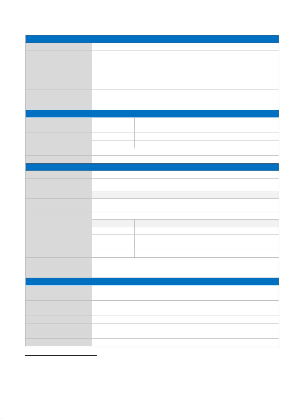
Technical data4.1
CPU
Class
Freescale ARM®-CortexTM-A8 i.MX537
Type/Clock
800 MHz
Features
NEON SIMD media acceleration and VFP operations
L1 cache, 32 KB for instruction, 32 KB for data
Unified 256 KB L2 Cache
Multi-format HD 1080p video decoder and HD 720p video encoder hardware
engine
HW Accelerators
RTC
Depending on ambient temperature
Standard time´s deviation: +/- 30 ppm at 25°C
Memory
NAND Flash
Standard
512 MB SLC NAND-Flash
Maximum
Up to 2 GB SLC (not tested, yet)
RAM
Standard
512 MB DDR3-RAM
Maximum
Up to 2 GB (not tested, yet)
SRAM
512 KB SRAM (optional)
SD Card Slot
4 bit MMC/SD(HC)
Interfaces External
Network
1x 10/100 Mbit/s Ethernet (RJ45)
Serial
2x RS-232 (RX/TX/CTS/RTS)
1x RS-485, galv. isolated together with CAN
MDB*1
1x MDB (Master / Slave optional)2instead of 2nd external RS-232
High-Speed USB 2.0
1x 480 Mbit/s Host (Type A)
1x 480 Mbit/s OTG (Type Micro-AB)3
CAN Fieldbus
1x CAN (ISO/DIS 11898), galv. isolated together with RS-485
CAN2*1
2nd CAN instead of RS-485
Keypad/SPI/I²C
multiplexed
Default
1x 7x7 Keypad, 1x I²C
Mode 1
1x 4x4 Keypad, 1x I²C, 1x SPI
Mode 2
1x 8x8 Keypad
Mode 3
1x 5x5 Keypad, 1x SPI
Speaker
1x external speaker (connector) 1W RMS )
1x internal speaker Output sound pressure level (S.P.L.) 85 +-3 db/0.3 W 0.5m
Digital I/O
2x Input, 2x Output (700 mA), VDD = VDC (power supply)
LCD Display
Size [inch/mm]
7.0 / 177.7
Display Technology
TFT TN
Width x Height [pixel]
800 x 480
Colours
262,144 (18 bit)
Backlight Unit
LED
Luminance4[cd/m²]
320 (Min.) 400 (Typ)
Active Area W x H [mm]
152.4 x 91.44
Viewing Angle
Typ. 60 / 70 / 70 / 70
Condition CR>10
1
Option
2
The selection of a variant eliminates the other.
3
Mechanically the Micro-USB interface has not been designed for frequent contact operations. Please use an adapter cable
with a strain relief.
4
Luminance applies to the entire device.

VINCELL 7.0" Boxed Manual
9
Resistive Touch
Type
4-wire analog resistive
Linearity
<=1.5%
Surface Treatment
antiglare
Power Supply and Consumption
Supply [V DC]
Nom. 24 ± 15%
Max. 9 ~ 36
PoE Supply (optional)
IEEE 802.3at-2009 class 4
Consumption [W]
Typ. 4.8
Internal Backup Battery
(RTC and SRAM)
Type
3 V lithium manganese dioxide Type CR1220
Lifetime (RTC only)
Approximately 8 years, depending on application
Lifetime (RTC+SRAM)
Approximately 2 years (75% power down)
Housing
Back Cover
1.4016 high quality steel, polished, 0.8mm
Front
Frame 4 mm AlMg3
Décor 180µ ± 10% polyester film, antiglare, 91% ± 2% luminous
transmission, pencil hardness 3H (refer to D-2 Decor Film Properties)
Approximate Dimensions
W x H x D [mm]
tbd.
Weight [g]
490
Environment
Humidity [%]
5 ~ 95 (non condensating)
Ingress Protection
IP 20
Operating Temperature [°C]
0 ~ +60
Storage Temperature [°C]
-20 ~ +70
Max. Operating Altitude [m]
up to 3,000 (10,000 ft)
Max. Storage/Transit
Altitude [m]
up to 10,000 (32,814 ft)
Noise Level [db(A)] @ 1m
<<40 (fanless design)
Lifetime
Backlight Lifetime5LCD
Display [h]
40,000
Operating Lifetime Touch
100,000 (by pen), 1,000,000 (by finger)
MTBF6[h]
000
5
Backlight lifetime is dictated by the LCD manufacture´s specification. Backlight lifetime is the approximate time at which
the brightness decreases to half of its original brightness. Reduction of brightness due to backlight lifetime is not
considered as failure. It is a natural aging of all electronic components.
6
Electrical products use the industrial standard term Mean Time between Failure (MTBF) as a statistical prediction of the
elapsed time between failures in a large population of systems.
The MTBF of all Garz & Fricke HMI products shall be 50,000 hours
A failure is anything that causes the product not to function to its specifications
Reduction in brightness due to backlight lifetime is not a failure
If the LCD used in the system exceeds its pixel defect specification it is considered a failure

VINCELL 7.0" Boxed Manual
10
PCB design 4.2
As this manual describes an boxed version, only the external interfaces
will be mentioned in the following chapter
Pos.
Description
Pos.
Description
1
Ethernet (X24)
8
USB - Host (X34)
2
Power (X1)
9
USB - OTG (X20)
3
Digital I/O (X14)
10
SD card reader (X31)
4
CAN/RS-485 Interface (X39)
11
Reset Switch (SW1)
5
Speaker (X9)
12
Clear all Switch (SW2)7
6
Keypad/SPI (X21)
13
Status LED (D30)
7
RS-232/MDB (X13)
7
For the function of this switch please refer to the RedBoot BIOS Manual Part 5.2.7 Boot-

VINCELL 7.0" Boxed Manual
11
5 Installation and start up
The content of this document is limited to explain the device connectors and how to access VINCELL via FTP
over your local area network (LAN) within a few seconds. For advanced hardware specifications and software
support, please refer to chapter 3.3
Product
Link to Garz & Fricke Website
VINCELL 7.0" Boxed
http://www.garz-fricke.com/vincell-70-boxed_en.html
Connection Scheme 5.1
(Exemplary illustration)
VINCELL 7.0" Boxed Manual
12
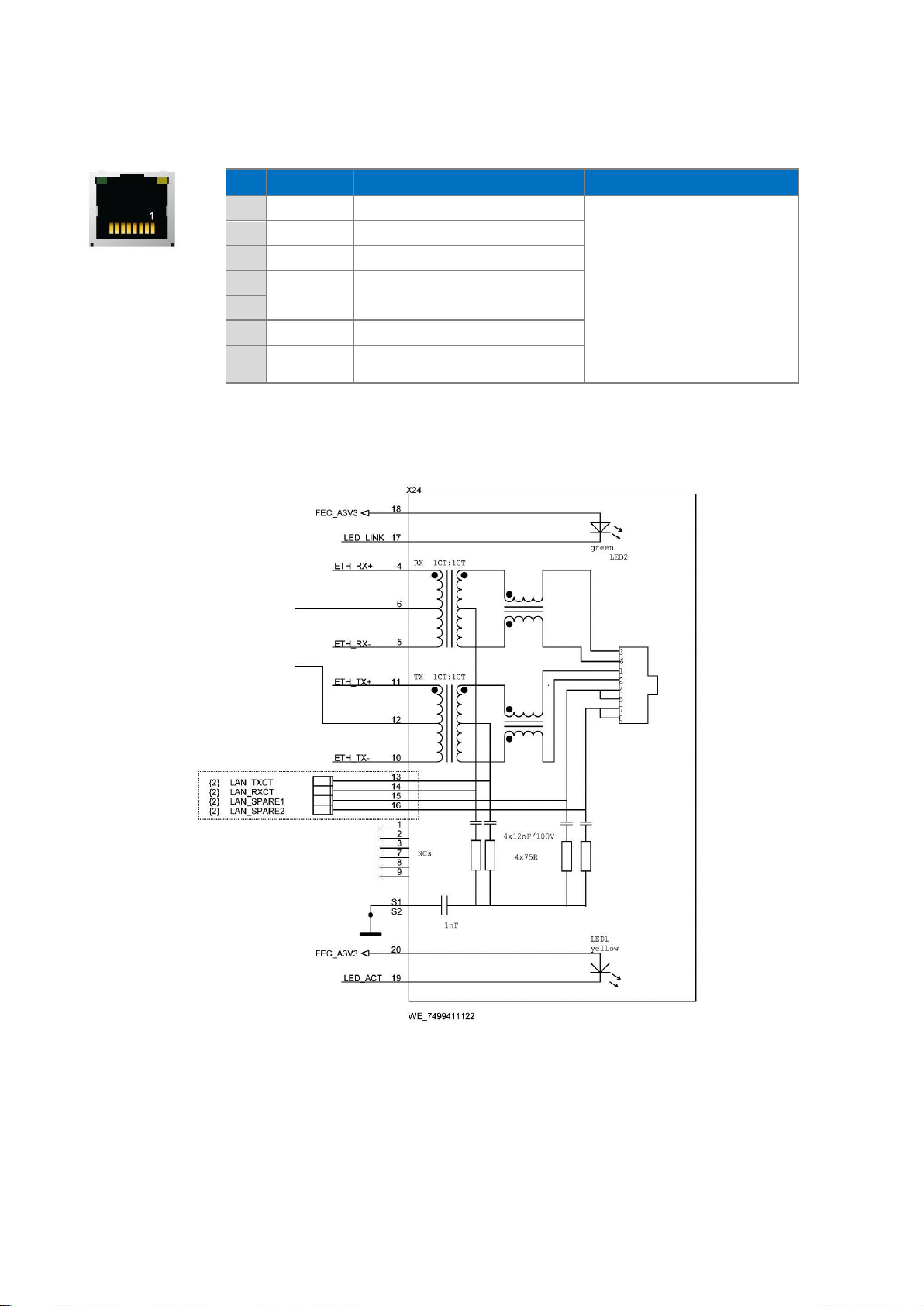
6 External interfaces and Schematics
Ethernet (X24)6.1
Pin
Name
Description
Information
1
Tx+
Rx/Tx might be swapped
(Auto-MDIX)
+/- might be swapped
(Autom. polarity correction)
PoE might also be injected
via Rx/Tx lines.
2
Tx-
3
Rx+
4
SPARE1
Power Supply (PoE)
5
6
Rx-
7
SPARE2
Power Supply (PoE)
8
Header:
RJ45
VINCELL 7.0" Boxed Manual
13
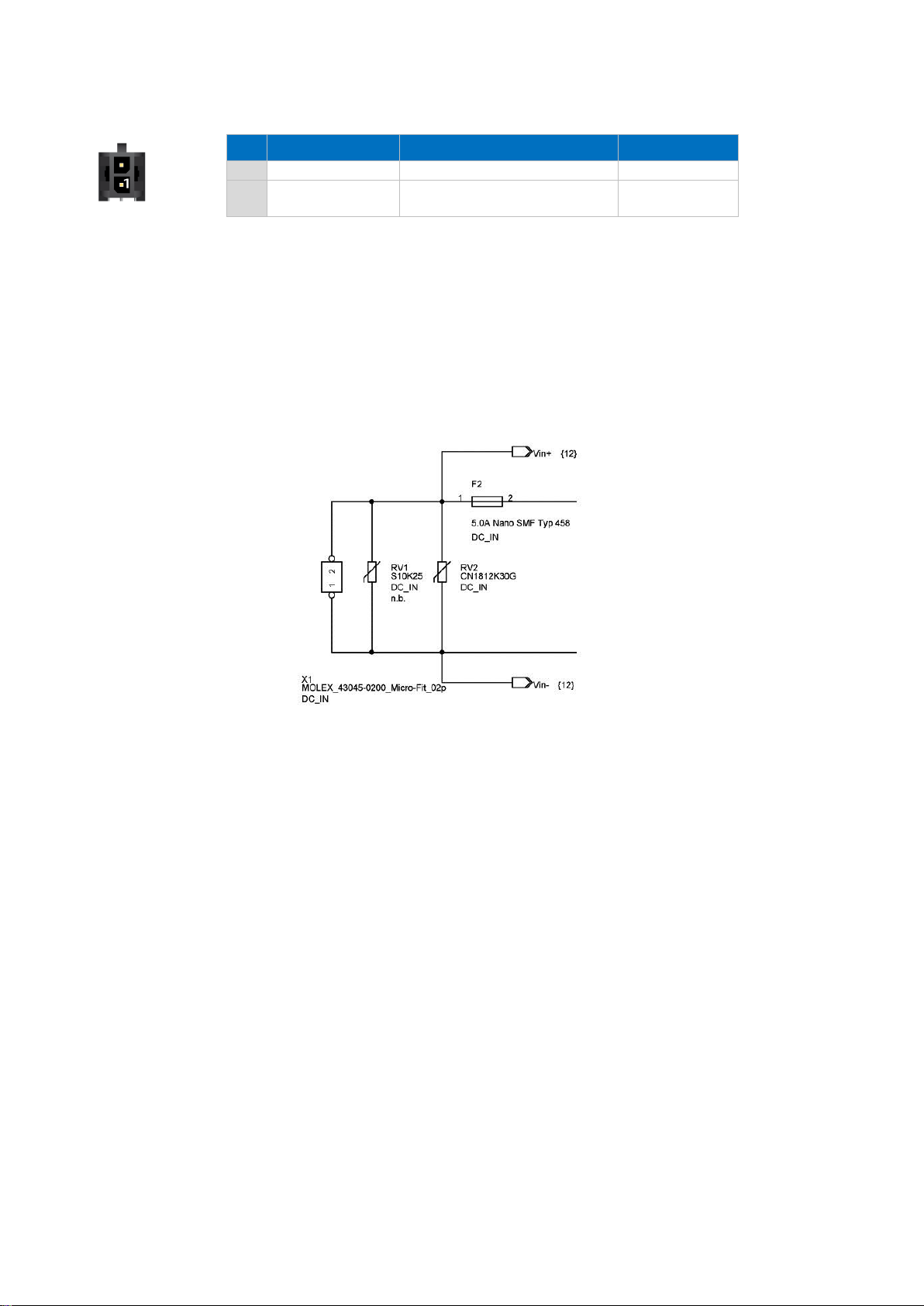
Power (X1)6.2
Pin
Name
Description
Level
1
GND
DC Ground
0V
2
Vcc_In
DC Input voltage
Nom. 24 ± 15%
Max. 9
Header:
Molex 43045-0200 Micro-Fit 2p
Plug: Molex 43025-0200 Micro-Fit 2p,
crimp contact Molex 43030-0007
Shielding with 6,3 mm male spade terminal connector
Pin 1 (GND) is connected to frame/housing through L129. GND/Vcc_In is
not galvanic isolated from System-GND
VINCELL 7.0" Boxed Manual
14
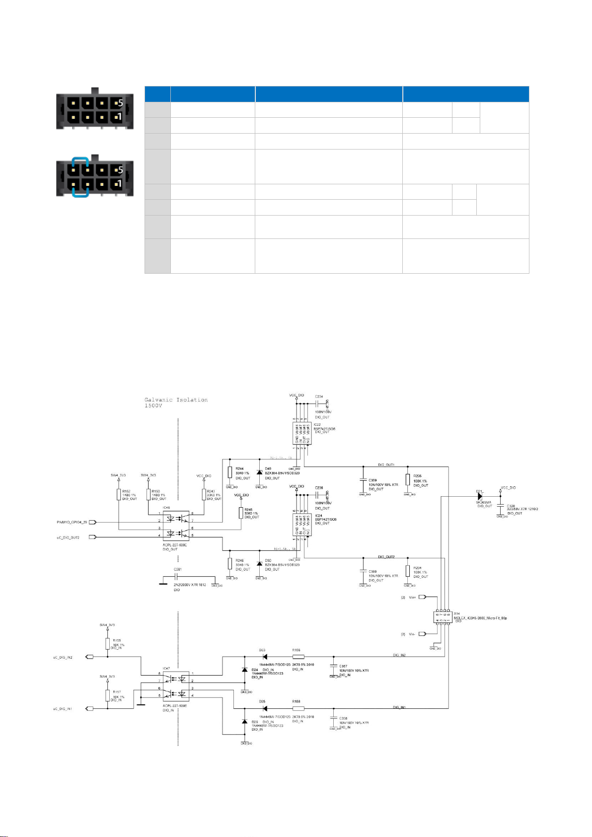
Digital I/O (X14)6.3
Pin
Name
Description
Level
1
DIG_IN1
Input 1
0V
Low
Typ. 8.3
mA / 24 V
2
DIG_IN2
Input 2
3-36V
High
3
GND_DIO
Ground for digital IO group
4
GND
Common ground, can be
bridged with GND_DIO, when
galvanic isolation is not required
5
DIG_OUT1
Output 1
0V
Low
Max. 800
mA / 24 V
6
DIG_OUT2
Output 2
Vcc_DIO
High
7
Vcc_DIO
Supply input for digital IO
group
<36 V
8
Vcc
Supply output, can be bridged
with Vcc_DIO, when galvanic
isolation is not required
Vcc_In
Header:
Molex 43045-0800 Micro-Fit 8p
Plug: Molex 43025-0800 Micro-Fit 8p, crimp contact Molex 43030-0007
Shielding with 6,3 mm male spade terminal connector
Digital I/O (X14) is not galvanic isolated from System-GND/Housing
VINCELL 7.0" Boxed Manual
15
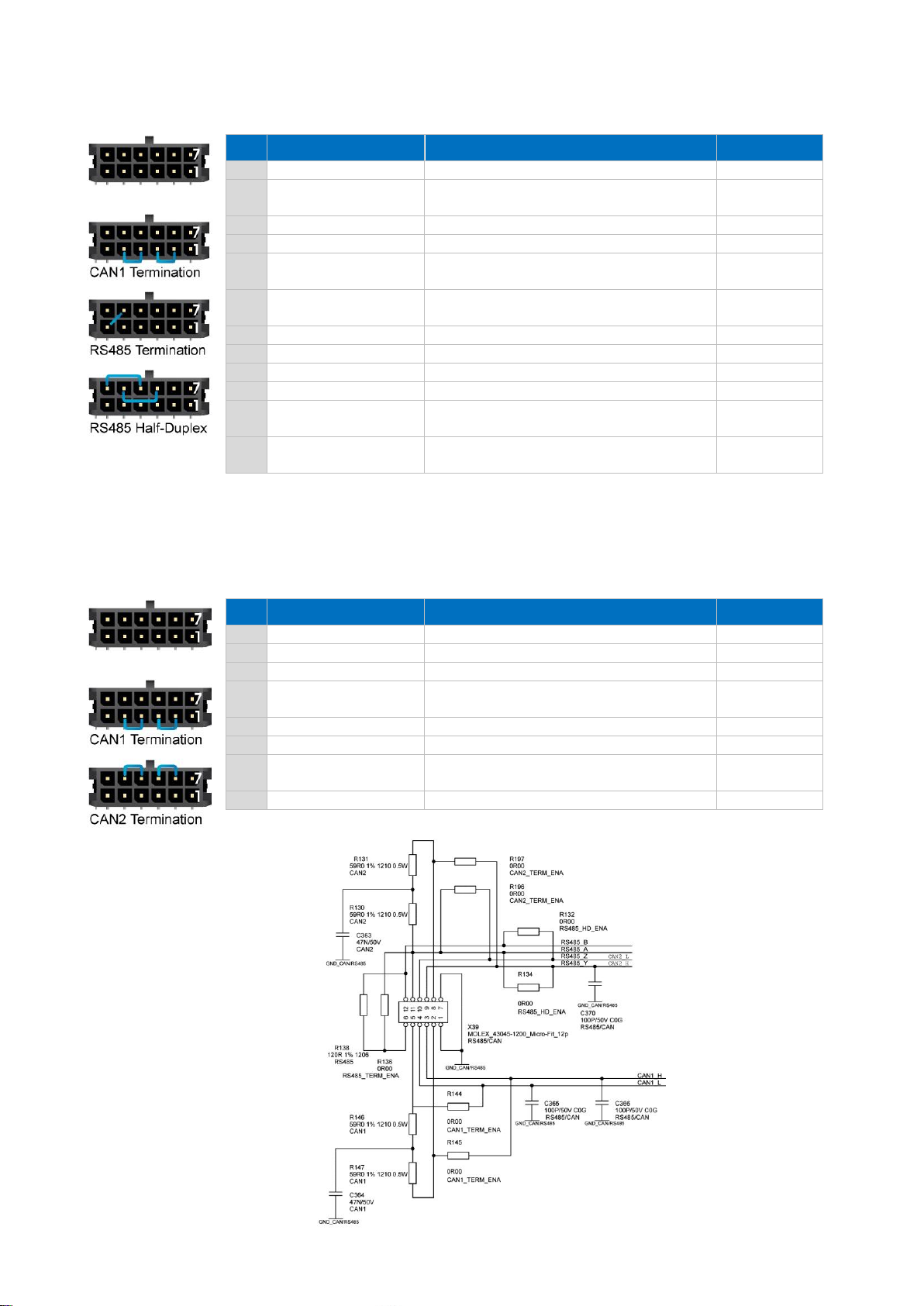
CAN/RS-485 Interface (X39)6.4
Pin
Name
Description
Level
1
GND_CAN_RS485
Ground for CAN and RS485 group
2
CAN1_TERM
To enable CAN1-Termination, bridge
with CAN1_H
3
CAN1_H
CAN bus 1 high
-
4
CAN1_L
CAN bus 1 low
-
5
CAN1_TERM
To enable CAN1-Termination, bridge
with CAN1_L
6
RS485_TERM
To enable RS485-Termination: bridge
with RS485_A
7
GND_CAN_RS485
Ground for CAN and RS485 group
8
n.a.
9
RS485_Y
TX+
-
10
RS485_Z
TX-
-
11
RS485_A
RX+, to enable Half-Duplex: bridge with
RS485_Y
12
RS485_B
RX- , to enable Half-Duplex: bridge with
RS485_Z
Header:
Molex 43045-1200 Micro-Fit 12p
Plug: Molex 43025-1200 Micro-Fit 12p, crimp contact Molex 43030-0007
Shielding with 6,3 mm male spade terminal connector
CAN/RS-485 (X14) is not galvanic isolated from System-GND/Housing
CAN1/CAN2 *
Pin
Name
Description
Level
1-5
Identical to standard
6
n.a.
7
GND_CAN_RS485
Ground for CAN group
8
CAN2_TERM
To enable CAN2-Termination, bridge
with CAN2_H
9
CAN2_H
CAN bus 2 high
- V
10
CAN2_L
CAN bus 2 low
- V
11
CAN2_TERM
To enable CAN2-Termination, bridge
with CAN2_L
12
n.a.

VINCELL 7.0" Boxed Manual
16
Speaker (X9)6.5
Pin
Name
Description
Level
1
VO+
Speaker out +
2
VO-
Speaker out -
Header:
JST S2B-PH-SM3-TB, side entry, RM = 2.0, 2-pin
Plug:
JST PHR-2, crimp contact BPH-002T-P0.5S

VINCELL 7.0" Boxed Manual
17
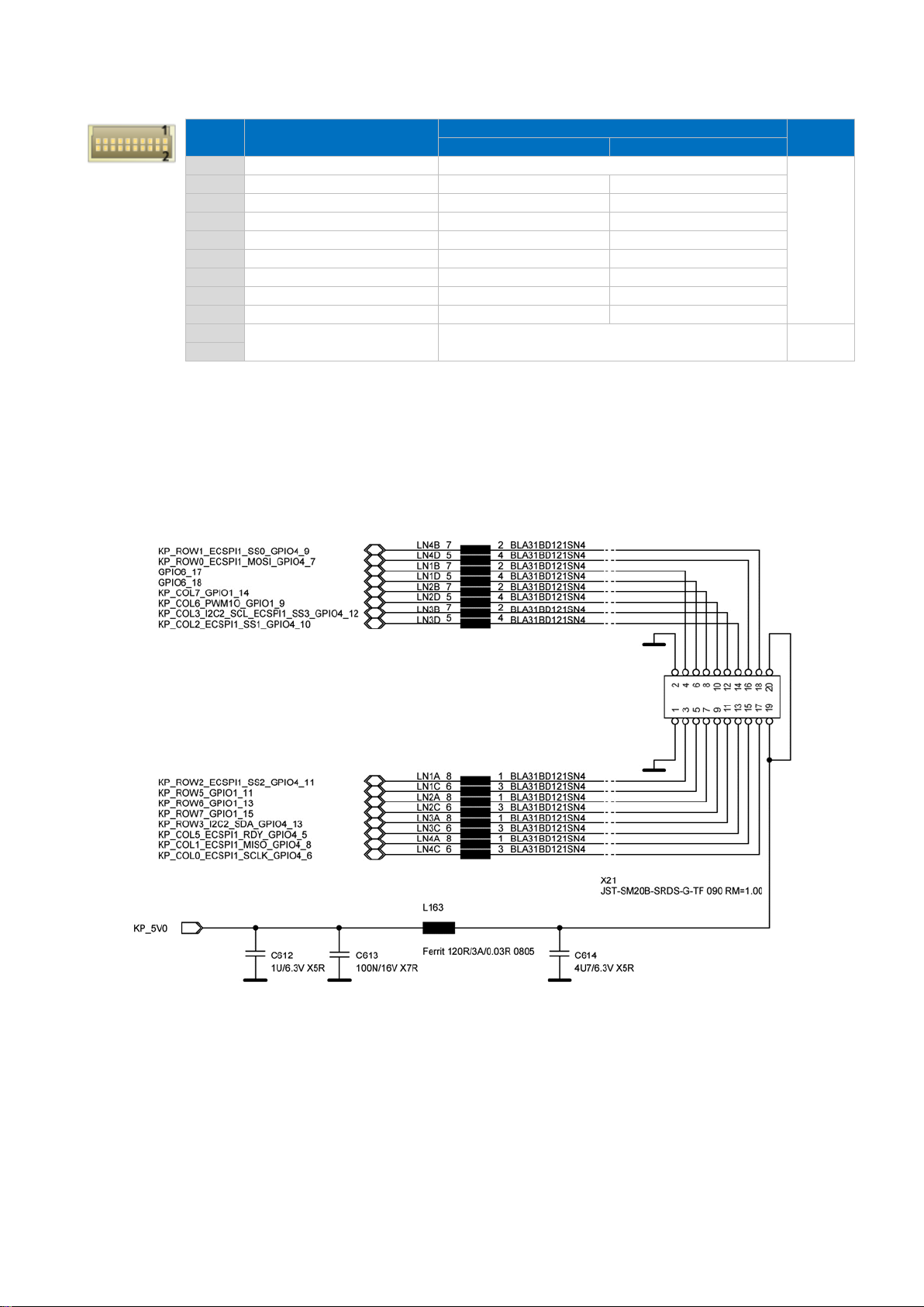
Keypad/SPI (X21)6.6
Keypad/SPI/I²C, multiplexed
Pin
Name
Description
Level
Default mode
Mode 1
1
GND
Ground
Ground
3.3 V
2
GND
Ground
Ground
3
KP_ROW0
Keypad row 0
Keypad row 0
4
KP_COL0
Keypad column 0
Keypad column 0
5
KP_ROW1
Keypad row 1
Keypad row 1
6
KP_COL1
Keypad column 1
Keypad column 1
7
KP_ROW2
Keypad row 2
Keypad row 2
8
KP_COL2
Keypad column 2
Keypad column 2
9
KP_ROW3
Keypad row 3
Keypad row 3
10
KP_COL3
Keypad column 3
Keypad column 3
11
KP_ROW4
I²C2 SDA
I²C2 SDA
12
KP_COL4
I²C2 SCL
I²C2 SCL
13
KP_ROW5_DMA
Keypad row 5
SPI Interrupt Request
14
KP_COL5_SS1
Keypad column 5
SPI Slave Select 1
15
KP_ROW6_MISO
Keypad row 6
SPI Master in Slave out
16
KP_COL6_MOSI
Keypad column 6
SPI Master out Slave in
17
KP_ROW7_SLK
Keypad row 7
SPI Serial Clock
18
KP_COL7_SS0
Keypad column 7
SPI Slave Select 0
19
Aux_Out
500 mA (can be controlled by software)
5.0 V
20
Header:
JST SM20B-SRDS-G-TF, side entry, RM = 1.00
Plug:
JST SHDR-20V-S-B, crimp contact: SSH-003GA-P0.2
VINCELL 7.0" Boxed Manual
18
Keypad/SPI/I²C, multiplexed 1*
Pin
Name
Description
Level
Mode 2
Mode 3
1-10
Identical to standard
3.3 V
11
KP_ROW4
Keypad row 4
Keypad row 4
12
KP_COL4
Keypad column 4
Keypad column 4
13
KP_ROW5_DMA
Keypad row 5
SPI Interrupt Request
14
KP_COL5_SS1
Keypad column 5
SPI Slave Select 1
15
KP_ROW6_MISO
Keypad row 6
SPI Master in Slave out
16
KP_COL6_MOSI
Keypad column 6
SPI Master out Slave in
17
KP_ROW7_SLK
Keypad row 7
SPI Serial Clock
18
KP_COL7_SS0
Keypad column 7
SPI Slave Select 0
19
Aux_Out
500 mA (can be controlled by software)
5.0 V
20
1 R214 and R215 will not be assembled

VINCELL 7.0" Boxed Manual
19
RS-232/MDB (X13)6.7
RS-232/RS-232
Pin
Name
Description
Level
1
GND
Ground
2
RS232_TXD1
Port#1: Transmit data (Output)
3
RS232_RXD1
Port#1: Receive data (Input)
4
RS232_RTS1
Port#1: Request-to-send (Output)
5
RS232_CTS1
Port#1: Clear-to-send (Input)
6
GND
Ground
7
RS232_TXD2
Port#2: Transmit data (Output)
8
RS232_RXD2
Port#2: Receive data (Input)
9
RS232_RTS2
Port#2: Request-to-send (Output)
10
RS232_CTS2
Port#2: Clear-to-send (Input)
Header:
Molex 43045-1000 Micro-Fit 10p
Plug: Molex 43025-1000 Micro-Fit 10p,
crimp contact Molex 43030-0007
Shielding with 6,3 mm male spade terminal connector
RS-232/MDB (X13) is not galvanic isolated from System-GND/Housing
RS-232/MDB
Pin
Name
Description
Level
1-6
Identical to standard (pls. see 0)
7
MDB_TXD
MDB: Transmit data (Output)
8
MDB_RXD2
MDB: Receive data (Input)
9
MDB_WakeUp
MDB: WakeUp Signal (Output)
10
MDB: WakeUp PullUp VCC

VINCELL 7.0" Boxed Manual
20
USB - Host (X34)6.8
Pin
Name
Description
Level
1
USB_H1_VBUS
Power supply
+5 V DC
2
USB_H1_DN
Data minus (D-)
3
USB_H1_DP
Data plus (D+)
4
GND
Ground
Header:
USB Type A
USB - OTG (X20)6.9
Pin
Name
Description
Level
1
USB_OTG_VBUS
Power supply
+5 V DC
2
USB_OTG_DN
Data minus (D-)
3
USB_OTG_DP
Data plus (D+)
4
USB-OTG_ID
Device ID
5
GND
Ground
Header:
Micro-USB Type AB
Table of contents
Other GARZ&FRICKE Desktop manuals


