manuals.online logo
Brands
  1. Home
  2. •
  3. Brands
  4. •
  5. Sharp
  6. •
  7. Desktop
  8. •
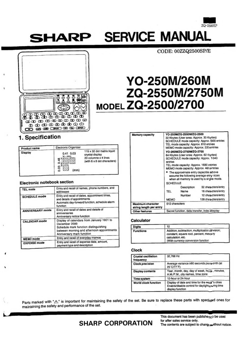
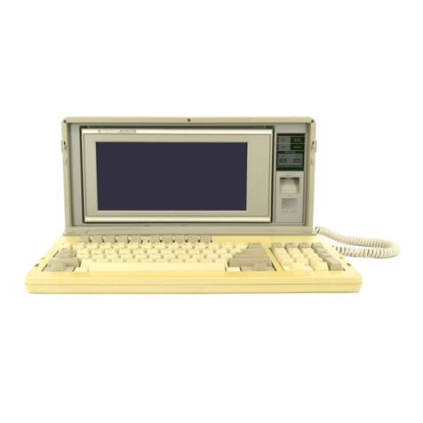
  9. Sharp Mobilon HC-4000 User manual

Sharp Mobilon HC-4000 User manual

SERVICE MANUAL
CODE: 00ZHC4000SP/E
Handheld PC
MODEL HC-4000
MODEL HC-4100
CHAPTER 1. SPECIFICATION . . . . . . . . . . . . . . . . . . . . . . . . . . . . . . . . . . . . . 1
CHAPTER 2. HARDWARE DESCRIPTION. . . . . . . . . . . . . . . . . . . . . . . . . . . . .
CHAPTER 3. NOTE FOR SERVICING . . . . . . . . . . . . . . . . . . . . . . . . . . . . . . . .
CHAPTER 4. DISASSEMBLY AND ASSEMBLY. . . . . . . . . . . . . . . . . . . . . . . . .
CHAPTER 5. DIAGNOSTICS AND CHECK ITEMS . . . . . . . . . . . . . . . . . . . . . .
CHAPTER 6. CIRCUIT DIAGRAM & PARTS LAYOUT. . . . . . . . . . . . . . . . . . . .
PARTS GUIDE
CONTENTS
SHARP CORPORATION This document has been published to be used for
after sales service only.
The contents are subject to change without notice.
Parts marked with "! " is important for maintaining the safety of the set. Be sure to replace these parts with specified
ones for maintaining the safety and performance of the set.
CHAPTER 1. SPECIFICATION
The HC-4000/HC-4100 is a handheld PC using the Microsoft® Win-
dows® CE 2.0 operating system, which is very similar to the Mi-
crosoft Windows95 and Windows NT 4.0 operating systems.
The Microsoft Windows® CE 2.0 operating system comes standard
with the following applications:
•Pocket Word
•Pocket Excel
•Pocket PowerPoint
•Windows CE Services 2.0
•Pocket Internet Explorer
•Pocket Outlook(Contacts/Calendar/Tasks/Inbox)
Additional applications from SHARP added to the unit make your
mobile life even more comfortable:
•Image Editor (to edit images)
•Voice Recorder (to record audio notes)
•IR Data Exchange with SHARP ZR series units
DISPLAY SECTION
ELEMENT: DFSTN LCD
DISPLAY: 640 ×240 dot
grayscale high
contrast with backlight,
DFSTN LCD
LSI
CPU: LH5809
ASIC: LH58172
POWER SUPPLY
Main: 3V DC, 2 AA-size (LR6) alkaline batteries,
NiMH Rechargeable Battery Pack (option),
AC adaptor (option)
Backup: 3V DC, CR2032 lithium battery
POWER CONSUMPTION
1.8 W
AUTO POWER OFF TIME
15 minutes
MEMORY PROTECT
Yes
DIMENSIONS
Open: 186 (W) ×187 (D) ×14.1 (H) mm.
Closed: 186 (W) ×93.5 (D) ×26.4 (H) mm.
Weight
Approx. 410 g including batteries
Interfaces
RS-232C
RJ-11
Infrared port (IrDA compliant), IR send distance: 50 cm (20 inch), IR
distance may change depending on the system used.
PC Card slot: 1 (Type II)
Internal Fax/Modem
Transmission speed: Data modem 33.6 kbps, Fax modem 9.6 kbps
Dialing capability: Tone and Pulse
Data communication
command: Data modem AT command set, FAX modem
EIA/TIA 578 class 1, Autodial YES
Memory
4 MB (HC-4000)
8 MB (HC-4100)
ROM
16 MB
Battery life
Main: 2 AA-size (LR6) alkaline batteries, 000 hours
approx.
NiMH Rechargeable Battery Pack, 000 hours
approx.
Main battery life varies considerably depend-
ing on usage.
Backup: 1 month approx. (HC-4000)
2 weeks approx. (HC-4100)
(with depleted main batteries)
5 years approx. (with replacement of depleted
main batteries)
Operating temperature: 32°to 104°F (0° to 40°C)
Accessories
Serial cable, Modular phone cable, CD-ROM from Microsoft, CD-
ROM from SHARP, Two AA alkaline batteries, CR2032 lithium bat-
tery, Operation Manual
0.21
0.24
0.26
0.23
(mm)
– 1 –
Part names and functions
1RESET button
Press to reset and initialize the unit.
2Application keys
Press to start the indicated application.
3Display
Shows information and also functions as a "touch panel" for se-
lecting operations, data entry, etc.
4Backlight key
Press to turn the backlight on or off.
5Notification indicator
Flashes red when a schedule alarm time is reached.
Solid green when the modem or microphone is in use.
Solid amber when the optional NiMH Rechargeable Battery Pack
is charging.
6OFF key
Press to turn off the unit.
7ON key
Press to turn on the unit.
8PC Card slot
For inserting a Type II PCMCIA card.
9Stylus
Use it to write on the display or navigate through the software.
FRelease button
Press to open the unit.
GRecord button
Press and keep holding for quick recording.
HAlarm stop button
Stop the schedule alarm and clear the Notification indicator.
IMicrophone
For voice note or other recording.
JModem jack
For fax and data communication.
1PC Card eject switch
Slide to eject the inserted PC Card.
2Battery replacement switch
For replacing main batteries as well as the backup battery.
3Main battery holder
Holds two AA alkaline batteries, or can be replaced with the op-
tional NiMH Rechargeable Battery Pack.
4Infrared port
For wireless communication with other handheld PCs and infra-
red-capable notebook and desktop PCs, and printing to infrared-
capable printers.
5DC power jack
For connecting to the AC adaptor included in the optional Docking
Station Kit.
6Serial port
For connecting to a desktop PC for data transfer or to a printer for
printing.
7Memory module cover
Open to replace the Memory module, if necessary.
8Speaker
9Backup battery cover
Open to replace the backup battery.
Microphone
13
Hodem jack
14
Alarm stop button
12
Record button
11
Release button
10
Stylus
9
PC Card slot
8
ON key
7
OFF key
6
Notification indicator
5
Backlight key
4
Display
3
Application keys
2
RESET button
1
PC Card eject switch
1
Backup battery cover
9
Speaker
8
Memory module cover
7
Serial port
6
DC power jack
5
Infrared port
4
Main battery holder
3
Battery
2
replacement switch
– 2 –
Serial cable
(Attached to the main body)
Serial cable
MS version CD-ROM
Sharp version CD-ROM
Modular cable
AC adapter
(Cradle kit attached)
Modular cable
(attached to the
main body)
To analog line
IrDA system
IR board
RJ-11
AC adapter
Serial port
Video output card
Bi-directional paper (Commrtcially available)
GSM adapter
Fax/MODEM *2 (Commercially available)
* Video output card : EZCard2TV ($229) of EZ show systems, Inc.,
Microsoft version (Attached to the
main body)
AHARP version (Attached to the
main body)
HPC Explored
Power PIMM
Data conversion software from
Zaurus, Wizard
AC adapter
Serial port
Battery pack (Option/cradle kit attached)
Spare battery charging box
*1: IrDA system is supported/
Speed: Max. 115Kbps
ASK system is not supported.
For wizard, data import is allowed
through PC.
*2: Fax/MODEM is built in the
models for North America only.
For the other areas, use
commercially
available GSM adapter card
or MODEM CARD.
Optional peripheral
device
HC-4000/4100
ZAURUS
HC-4000/4100 package
Serial port
connection
RAM card/flash/memory card (ATM)
(Commercially available)
SYSTEM CONFIGURATION
Battery box
PC card
slot
Memory module
Battery pack
(Option/cradle kit attached)
Digital camera card
– 3 –
CHAPTER 3. NOTE FOR SERVICING
Caution:
1. This unit employs a PSRAM instead of a conventional SRAM for
memory. The PSRAM allows to flow a standby current of 20 times
as great as that flowing in an SRAM.
Similarly to the conventional models, the main battery is packed
together with the unit and the backup battery is installed in the
unit. The backup battery may be exhausted before arriving at the
user. In order to prevent against this, power supply to the PSRAM
is electrically halted in the shipment setting.
(Note) When servicing also, do not leave the backup battery
without necessary treatment.
2. Before executing disassembly, assembly, diagnostic, rewriting of
the flash EEPROM, etc., be sure to save the user data. (Refer to
"4. Data exchange.") After servicing, set the clock to the punctual
time and return the set to the user. (The clock is initialized by
servicing.)
1. Shipment setting
Shipment setting procedure (After the inspection, be sure to per-
form the following shipment setting).
When diag "40 DISABLE BACKUP BATTERY" is selected, the follow-
ing display is shown and the setting circuit is turned off by the soft-
ware. (The power to VRAM is cut off.)
BACKUP BATTERY DISABLE
OK
•Setting circuit state check
•When the setting circuit is off (Power to VRAM is cut off.)
•When the voltage between check pad "VRAM" and "GND" is 0 ∼
0.5V, the setting circuit is off.
•When the setting circuit is on (Power to VRAM is supplied.)
•When the voltage between check pad "VRAM" and "GND" is 2.3V
or above, the setting circuit is on.
(Note) In the ZR-5700/5800, never make the following settings be-
fore shipment, which will fasten backup battery exhaustion.
B and S keys
B and C keys
2. Resetting the HC-4000/4100
If the unit stops responding while you are using it, you can reset the
unit. Make sure the unit is turned on, and then press the RESET
button with the stylus.
Caution:
The reset function will not work if the unit is turned off when you press
the RESET button.
If the problem still persists after you have reset the unit, try the
following (full reset) remedy.
Caution:
The following procedure will cause all data on the unit to be lost and
you must restore data from your previous backup. However, any data
added or modified after your last backup will be lost permanently.
1. Turn off the unit
2. Remove the backup battery.
3. Remove the main batteries.
4. Wait for 30 seconds, then reinstall the main batteries and the
backup battery.
5. Turn on and re-setup the unit using the H/PC Setup Wizard.
6. Restore your data from a backup.
Note:
If you forget your password, you must set up your unit again, using
the above steps.
3. Battery Replacement
When the batteries are low, your unit displays warning messages
prompting you to replace the batteries as soon as possible. You can
also check the battery power by double-tapping the power status icon
if it appears on the task bar.
Replacing the main batteries
1. Turn off the unit.
OFF ON
– 35 –
2. Slide the battery replacement switch to the REPLACE MAIN BAT-
TERIES position.
3. Pull out the battery holder and remove the old batteries. Discard
them properly.
4. Insert two new AA alkaline batteries into the battery holder, noting
the directions indicated by the plus (+) and minus (–) signs inside
the holder.
5. Reattach the battery holder to the unit, noting the position of the
projecting part on the battery holder.
6. Slide the battery replacement switch back to the NORMAL OP-
ERATION position.
If this proves difficult, check to make sure the main battery holder
is completely inserted.
7. After battery replacement, turn on the unit and make sure no
warning message appears.
Replacing the backup battery
1. Turn off the unit.
2. Slide the battery replacement switch to the REPLACE BACKUP
BATTERY position.
3. Use a ballpoint pen to open the backup battery cover. Do not use
the stylus.
4. Remove the old backup battery with a ballpoint pen.
5. Insert a new CR-2032 lithium battery with the plus (+) sign facing
up.
6. Put the backup battery cover back in place and slide the battery
replacement switch to the NORMAL OPERATION position.
7. After battery replacement, turn on the unit and make sure no
warning message appears.
NORMAL OPERATION REPLACE MAIN BATTRIES
REPLACE BACKUP BATTERY
NORMAL OPERATION
REPLACE MAIN BATTRIES
REPLACE BACKUP BATTERY
– 36 –
About power source
•You can use two AA alkaline batteries or the optional NiMH Re-
chargeable Battery Pack to power your unit, or the AC adaptor
included in the optional Docking Station Kit.
•If the main batteries are not installed, or are depleted, the unit will
not function even when connected to an AC power source.
•Caution: When the main batteries are depleted, replace them
promptly with new batteries. If the depleted main batteries are not
replaced, the backup battery will be drained more quickly than
normal, and data loss may occur after about 2 weeks.
•?????
Important points to remember when installing new batteries:
•Be sure not to use any of the following as main batteries: manga-
nese batteries or nickel cadmium rechargeable batteries. These
are easily mistaken for alkaline batteries.
•Do not remove the main batteries and the backup battery at the
same time (this will result in the loss of all stored data).
•Backup important data before replacing batteries.
•Replace both main batteries at the same time with new batteries of
the same type.
•When the main battery low warning message and the backup
battery low warning message appear at the same time, replace the
backup battery first. After the backup battery replacement, turn on
your unit and make sure the backup battery low message is gone,
then you can proceed to replace the main batteries.
Caution:
•Keep batteries out of the reach of children.
•Danger of explosion if batteries are incorrectly replaced. Replace
only with the same or equivalent type recommended by the manu-
facturer. Discard used batteries according to the manufacturer’s
instructions.
•Backup battery: Replace battery with Panasonic type CR2032
only. Use of another battery may present a risk of fire of explosion.
See operation manual for safety instructions.
•Batteries may explode if mistreated. Do not recharge except the
optional NiMH Rechargeable Battery Pack, disassemble or dis-
pose of in fire.
Connecting the unit to your PC
You can connect the unit to your desktop PC to backup data, syn-
chronize activities, transfer files, etc.
Installing the Windows CE Services software
Before connecting the unit to a PC, you need to install the Windows
CE Services software on your PC and specify a serial port for use
with the unit. Use the supplied CD-ROM from Microsoft for the instal-
lation.
If this is the first time you are connecting the unit to your PC, the Set
Up New Partner Wizard will appear on the PC. Follow the instructions
to complete the setup.
Connect the unit to the desktop PC as follows:
1. Turn on the unit.
2. Flip open the serial port cover and push it into the unit as shown.
3. Insert the 18-pin end of the supplied serial cable into the serial
port on the unit.
4. Insert the other end of the cable into the serial port on your PC
that you specified during the Windows CE Services installation.
Using the infrared port for file transfer
You can use the built-in infrared port to transfer files with other hand-
held PCs compliant with the IrDA (115.2 kbps) standards.
Make sure both handheld PCs are turned on, then take the following
steps:
1. Align the two handheld PCs so that their infrared ports are facing
each other.
2. From the sending unit, tap to select the file to transfer.
3. On the receiving unit, tap Receive from the File menu, then spec-
ify the type of the sending unit.
4. On the sending unit, tap Send from the File menu, or tap Infrared
Recipient from Send To of the File menu. Specify the type of the
receiving unit, then start sending the data.
– 37 –
Using the internal fax/modem
You can use the internal fax/modem to perform fax and data trans-
mission (9.6 kbps for fax and 33.6 kbps for data).
Connect the internal fax/modem to an analog telephone line as fol-
lows:
1. Use a finger to gently open the modem port.
2. Insert one end of the supplied modular phone cable into the mo-
dem jack.
3. Insert the other end of the modular phone cable into a telephone
outlet.
Note:
Before using the internal fax/modem for communication, check that it
is set up in Windows CE.
Using a PC Card
Caution:
Not all PC Cards will work with the unit. Be sure to use only recom-
mended PC Cards. Using non-recommended PC Cards may cause
problems such as damage to the unit or the PC Card.
Contact your local dealer for more information on recommended PC
Cards.
Inserting a PC Card
Insert the PC Card into the slot as far as it will go. Make sure the PC
Card is facing up. If the card will not go in, check the orientation.
Never force the card or it or the main unit may be damaged.
Removing a PC Card
1. Close all applications accessing, or otherwise utilizing, data on the
inserted PC Card.
2. Turn off the unit.
3. Slide the eject switch to release the PC Card, and remove it by
hand.
4. Data Exchange with other devices via IP
Data exchange with other devices via IR
You can exchange data with other devices such as SHARP ZR Se-
ries units, using infrared communication. The following tables indicate
the type of data you can exchange.
Your unit ZR Series unit How much data
Contacts Contact1 One or more contacts
Explorer PC Files One file
Your unit IrTran-P device How much data
Image Editor (depends on the device) One JPEG file
Note:
You must install the software program from SHARP CD-ROM before
exchanging data with the IrTran-P device.
– 38 –
Sending data from your unit
The following uses Contacts as an example.
1. Align your unit and the receiving unit so that their infrared ports
are facing each other.
2. On your unit, highlight the desired data.
3. Set the receiving unit to the receiving mode. In the case of
SHARP ZR Series unit, press the GET key.
4. On your unit, tap Send from the File menu, then select ZR Series
.
Note:
For Explorer files, select a file in step 2. In step 4, tap File, Send To,
and
Infrared Recipient to send the file.
Notes on field mapping when sending data to a ZR Series
unit
PC files are sent as they are without any conversion. For Contacts
data, the following rules apply:
•Contacts data on the unit is converted to Contact1 data on the ZR
Series unit.
•Restrictions on data sizes differ between the two units. On your
unit, there is a field size limit. On the ZR Series unit, the record
size must be less than 2048 bytes but there is no limit on the field
size. When data is received on the ZR Series unit, data exceeding
the 2048 byte limit is truncated.
•Since the name information on your unit is stored in several fields,
they are mapped into one single field on the ZR Series unit as
follows:
•Your unit used more fields in storing address information than the
ZR Series unit.
•The Name field on the ZR Series unit is always required. If this
field is empty, then the ZR Series unit will store it as Untitled.
Receiving data to your unit
The following uses contacts as an example.
1. Align your unit and the sending unit so that their infrared ports are
facing each other.
2. On the sending unit, highlight the desired data.
3. On your unit, tap Receive from the File menu, then select ZR
Series .
4. Set the sending unit to the sending mode. In case of SHARP ZR
Series unit, press SEND key, then start receiving the data.
Notes on field mapping when receiving data from ZR Se-
ries unit
PC files are received as they are without any conversion. For Con-
tacts data, the following rules apply:
•Contact1 data on the ZR Series unit is converted to Contacts data
on the handheld PC.
•Restrictions on data sizes differ between the two units. On the
handheld PC, there are limits on the field sizes as follows:
–Birthday and Anniversary are special fields for data input
–Notes field can be up to 14,998 bytes
–All other fields can be up to 1,023 bytes.
On the ZR Series unit, the record size must be less than 2048
bytes but there is no limit on the field size. When data is received
on the unit, data exceeding the field size limits is truncated.
•In the Unit to Unit dialog box on the ZR Series unit, turning on With
Link Information will not send the linked data to the handheld PC.
•Since the name information on the handheld PC is stored in sev-
eral fields, the name field on the ZR Series unit is split sd follows:
•The handheld PC uses more fields for storing address information
than the ZR Series unit. Therefore the fields are mapped as fol-
lows:
ZR unit
Mr/Ms/DR
Suffix
First
Middle
Last
Your unit
Mr/Ms/Dr/[SP]First[SP]Middle[SP]Last[SP]Suffix
ZR Series unit
City
State
ZIP
Country
Your unit
City, [SP]State[SP]ZIP[CR]
Country
ZR Series unit
Street Street[CR]
ZR unit
Your unit
Last Name
ZR Series unit
Last Name[SP]First Name
First Name
Last Name
First Name[SP]Last Name
First Name
Your unit
ZR Series unit
City
State
ZIP
Country
Street
City, [SP]State[LAST SP]ZIP[CR]
Country
Street[CR]
– 39 –
5. Flash Eeprom Service Writing/Checking
Procedures
The procedures are for writing into the FLASH-EEPROM in the ZR-
3000/3500X. Servicing for the ZR-3000/3500X is performed in the
following cases:
•When the MAIN PWB unit is replaced.
•When the MAIN ROM PWB is replaced.
•When the FLASH-EEPROM version is updated.
Introduction
Writing into the FLASH-EEPROM of the ZR-3000/3500X is performed
in the following procedures.
•Install the patch transfer program of the FLASH-EEPROM for IBM
PC.
•Connect the unit with the IBM PC and write.
5-1. Installing the patch transfer program of the
FLASH-EEPROM for IBM PC
1) Necessary devices
•IBM PC (compatible machine): MS-Windows 95 installed in the
hard disk
•Floppy disk 1 (*2): Check the label
ZR-3000/3500X ROM V1.0 or later
FLASH-EEPROM writing software
for MS-Windows 95
Ver F .F mm/dd/yy
Disk content:
\setup\*.* : Writing tool
\Z-lite(x).Vxx(*3): Data
*1: Trademark Microsoft
*2: Supplied by SHARP. In the future, it may be supplied through
the communication network instead of by a floppy disk.
*3: "xx" shows the version number.
2) Operating procedure
1. Turn on the power of the IBM-PC (compatible machine) to start
the MS-Windows.
2. Set the disk to IBM PC (compatible machine).
3. Start the explorer.
4. Make a working directory.
5. Use the explorer to execute\setup\setup.exe.
6. Follow the instruction of the install program.
[Note] DLL files are copied into the directory of \Windows\Systems.
5-2. Rewrite procedure of 1 Mbit FLASH-EEPROM in
the ZR-3000/3500X (ROM version 1.0 or later)
1) Necessary devices
•IBM-PC (Compatible machine): MS-Windows 95 installed in the
hard disk.
•AC adapter (EA-23E) for the ZR-3000/3500X: 1 unit
•Floppy Disk: 1 (*2): Check the label.
•RS-232C cross cable (Since the hardware flow is required, RTS
and CTS must be connected.)
•RS-232C level convertor [CE-137T]
ZR-3000/3500X ROM V1.0 or later
FLASH-EEPROM writing software
for MS-Windows 95
Ver F .F mm/dd/yy
Disk content:
\setup\*.* : Writing tool
\Z-lite(x).Vxx(*3): Data
*1: Trademark Microsoft
*2: Supplied by SHARP. In the future, it may be supplied through
the communication network instead of by a floppy disk.
*3: "xx" shows the version number.
2) Operating procedure
1. Connect the devices as shown below:
<Wiring diagram>
2. Turn on the power of the IBM-PC (compatible machine) to start
the MS-WINDOWS 95.
3. Start the explorer and start patch.exe.
<Operation on the unit side>
4. Set to the DIAG mode, and select (43 ERASE 1M FLASH).
The patch is erased.
5. Set to the DIAG mode, and select (47 UPDATE 1M FLASH).
The display shows "*****UPDATE 1MFLASH*****."
<Patch transfer program operation>
6. Use Browse button to select the patch file.
7. Select the COM PORT.
8. Push the send button to send the patch file.
Causes of errors on the unit side are as follows:
(1) SIO ERROR!!: The communication conditions are
not proper. Time-out (About 5 min).
Repeat the procedures again.
(2) ROM VER ERROR!!: The ROM version of ZR-3000/
3500X does not correspond to the
patch data.
(3) PATCH VER ERROR!!: The PATCH version of ZR-3000/
3500X is later than or the same as
the target patch data.
(4) LOW BATTERY!!: When ZR-3000/3500X is in low bat-
tery.
(5) ERROR!!: The other errors than the above.
On the unit side, the "X" bar extends along with the sound, and
the process content is shown on the bar.
READ: Reading of patch data
RS-232C Cross cable
IBM-PC
(compatible machine)
CE-137T
AC-adaptor
EA-23E
ZR-3000/3500X
DTR
RD
SD
SG
RI
DTR
RD
SD
SG
RI
4
2
3
5
9
21
3
2
7
22
CE-137T
DSUB-9Pin
PC
DSUB-25Pin
– 40 –
WRITE: Writing of patch data
VERIFY: Verifying patch data (The display is made in an in-
stant.)
9. End of patch writing
When patch writing is completed, the bar display is cleared. At the
same time, the check sum is displayed on the lower right side.
Note: The following operations of patch erase, write, and verify
should be performed immediately after entering the diag mode
by "ON" + "D" + "Reset."
Do not perform the operations after checking the other items.
43 ERASE 1M FLASH
45 VERIFY 1M FLASH
47 UPDATE 1M FLASH
5-3. Copying patch data to products from the
ZR-3500X master unit
<Tools>
1 ZR-3500X master unit
2 Data transfer cable CE-315L
(Procedure)
Connect the master set and the slave set with the cable.
(Slave side)
1. Start the DIAG menu. ("ON" + "D" + "RESET")
2. Touch the menu key three times.
3. Touch "43. ERASE 1M FLASH."
4. Touch "47. UPDATE 1M FLASH."
(Master side)
1. Start the DIAG. menu. ("ON" + "D" + "RESET")
2. Touch the menu key three times.
3. Touch "49. PATCH MASTER."
* NOTE: It is required that the master unit and the slave unit
should be of the same ROM version.
– 41 –
CHAPTER 4. DISASSEMBLY AND
ASSEMBLY
This chapter mainly describes the disassembly procedure. For as-
sembly, reverse the disassembly procedures. If any special care is
required for assembly, "Note for assembly" is provided.
Simple and easy replacement procedures of units and parts are omit-
ted.
[Flowchart of disassembly]
1 Memory PWB removal
1. Remove two screws 1 .
2. Remove ROM module cover 2 .
3. Remove one screw 3 .
4. Remove memory PWB 4 .
[Note for assembly]
1. Memory PWB attachment screw tightening
1) Fit and connect the docking connector of the main PWB and the
docking connector of the memory PWB.
2) Hold the memory PWB and tighten the screw.
* Tightening torque is 1.5Kgf⋅cm±7%
Note 1) When connecting the docking connectors, fit the main side
and the memory side properly and connect.
If positioning is improper, they may be broken.
Note 2) When removing the memory PWB, remove it from section A
.
If it is removed from the other section, a stress is applied to
the docking connectors.
2. Module cover attachment screw tightening
1) Insert two pawls of ROM module cover into the lower cabinet pawl
engagement positions to attach.
2) Tighten two ROM module attachment screws.
1Memory PWB removal
2
3Display unit and main PWB unit removal
4
6
Key bottom cabinet disassemblyKey bottom cabinet removal
Kry PWB unit removal
5
Display unit disassembly
7 Main PWB attachment process
Pen unit
Battery box unit
B/U Battery cover
1
2
3
4
1. memory PWB attachment screw tightening
Screw hole
Docking connectors
Memory PWB
2.Module cover attachment screw tightening
Screw hole
Memory PWB
Pawl insertion position
Pawl
Screw hole
ROM module
cover
– 40 –
* Tightening torque is 1.5Kgf⋅cm±7%
2 Key bottom cabinet removal
1. Remove eight screws 1 and remove key bottom cabinet 2 .
[Note for assembly]
1. Microphone attachment
1) Insert the connector until it is locked. (Be careful of inserting direc-
tion and bending.)
2) Insert the microphone body into the cabinet. (Be careful of the
inserting direction.)
3) Treat the wire not to cover the upper side of recording/indicator
button and screw hole A .
2. Speaker lead wire process
3. Key lower cabinet screw tightening
1) Tighten six screws ←A.
* Tightening torque: 1.6kgf⋅cm±7%
2) Tighten two screws ←B.
* Tightening torque: 0.6kgf⋅cm±7%
Microphone
Indicator filter
1
2
1
Microphone cone side
A
Keep the lead wire away from the parts.
A
AA
A
A
A
B
B
– 41 –
3Display unit and Main PWB unit removal
1. Remove two screws 1 .
2. Remove LCD FPC 2 and remove Display unit 3 .
3. Remove key FPC 4 and remove Main PWB unit 5 .
[Note for assembly]
1. Attach the display side unit to the key upper cabinet.
(1) Connect in the sequence of (1) -- (2) as shown in the figure below.
Close the display side unit (cover).
2. Tighten the return spring to the key upper cabinet with
a screw, then attach the recording/LED indicator re-
lease button.
3. PWB unit screw tightening (2 positions)
4. Battery terminal (+)(–) soldering conditions
Cover lock knob
Return spring
Serial port cover
1
2
3
1
Record
button
Cover lock spring
LED Indicator
release button
Batt. term Batt. term
Copper foil tape
2
1
Note: Fit teh return spring so that it's protruded portion faces
PWB (inner side).
Return spring
Cabinet unit under
the keyboard Record button LED indicator reset button
+
-
*Screw tightening torque:0.8Kg Cm 13%
* Tightening torque: 0.7kgf.cm 15%
+
-
(Soldered state)
Solder tip temperaturn 350 C or less
Soldering time 3sec or less
– 42 –
5. Copper foil tape attachment
Key cabinet side
(1) Temporarily attach the copper foil tape to be added to the PWB
unit as shown in the figure below.
(2) When soldering the battery terminals, solder the copper foil tape
together.
(3) Attach the display side unit, attach copper foil tape t the side of
the hinge unit, and tighten the key bottom cabinet together.
4Key PWB unit removal
1. Remove two screws 1 and remove chassis B 2 .
2. Remove fourteen screws 3 and remove key PWB unit 4 .
[Note for assembly]
1. Key upper cabinet key PWB unit screw tightening
(screw
×14pcs.)
Copper foil tape
PWB unit Attachment reference
PWB external shape
Battery terminal soldering
pad external shape
Soldering pad
Attachment reference
Copper foil tape Solder
Hinge unit Copper foil tape
PWB unit
Key rubber
Space key
Key upper cabinet
1
4
2
3
3
3
3
3
Key upper cabinet
Key PWB unit screw tightening (screw x 14 pcs.)
25%
* Tightening torque 0.4kgf.cm
+
-
– 43 –
2. Chassis B attachment to key upper cabinet (screw ×2
pcs)
5 Display unit disassembly
1. Remove two screws 1 and remove Display bottom cabinet 2 .
2. Remove two screws 3 and remove hinge unit 4 .
3. Remove two screws 5 , pressure angle 6 , and pressure rubber 7
.
4. Remove tablet unit 8 .
5. Remove LCD unit 9 .
[Note for assembly]
1. Attachment of tablet spacer to the tablet (Use the jig.)
2. Attachment of tablet unit to the LCD unit
* Tightening torque 0.4kgf.cm
Key upper cabinet
Chassis B screw tightening (screw x 2 pcs.)
Chassis B 25%
+
-
SHARP Badge
Cusion B
Cusion A
Table spacer
2
3
4
5
6
7
8
9
1
1
Do not extend.
Reference
Do not
extend.
Reference
Tablet
Tablet spacer
– 44 –
3. Pressing rubber/pressing angle attachment screw
tightening
4. Attachment/soldering of rug terminal with lead wire
(1) Tighten the hinge unit and the rug terminal together with a
screw.
1) First, fix the hinge unit with a screw on A side as shown in
the Fig. 1.
2) Put the rug terminal over the hinge unit screw tightening
section as shown in Fig. 1, tighten it together with the hinge
unit with a screw on B side as shown in Fig. 1.
(2) Lead wire wiring process
As shown in Fig. 2, move the lead wire to the right from the state
of Fig. 1 so that the lead wire is between the tablet pressing
angle (including a screw) and the LCD unit segment driver.
(Note) (1) Keep the lead wire away from the LED holder rib
(shaded section in the figure). (If, not, the lead wire may
be pinched between the display cabinet A (external cabi-
net) rib.)
(2) Keep the lead wire away from the tablet pressing angle
(including a screw). (The space between the display
cabinet A ceiling is insufficient.)
Lead wire work dimensions
(UL style 1571 AWG 28 lead)
LCD unit
Reference
Do not extend.
Reference
Tablet unit
After cleaning the BL PWB pin section (IPA),
fold the tablet unit pin section to the Seg
Do not
extend.
BL PWB
Display side unit
EL panel
Seg PWB
Pressing rubber attachment Pressing angle attachment Screw tightening
* Tightening torque: 1.0Kgf.cm 10%
+
-
shape jumper lead
Solder
Rug terminal
Hinge unit <Fig. 1>
AB
Tablet pressing
angle
Lead wire
Solder Segment driver
(TCP)
Rug terminal
<Fig. 2> LCD holder rib
1.5
+0.5
0
30
+5
0
1.5
+0.5
0
– 45 –
Soldering of rug terminal and lead wire
6 Key bottom cabinet disassembly
Rug terminal (QLUGE1005CCZZ)
(Note) Do not put solder on this side.
Solder
Key bottom cabinet
IR Filter
Sheet
Battery exchange knob
Spring
Battery box lock knob
IC Cord
cover
Speaker
Spring
– 46 –
7Main PWB attachment process
7. IR filter attachment
* Be careful of attaching direction
Insert into the arrow section
of the key lower cabinet.
Battery replacement SW knob
4. Battery replacement SW knob attachment
* Be careful of attachment position.
Attach to the
arrow section.
5. Battery box lock knob attachment
Battery box lock knob
Key lower cabinet
IR filter
Key lower cabinet
1. Blind sheet attachment
Do not
extend.
Do not cover.
3. Speaker insertion/screw tightening (3 positions)
Key lower cabinet Speaker lead wire must be in this range.
Speaker
0.5mm
Lock knob return spring attachment
Lock knob return spring
6. Attachment of lock knob return spring to the battery box lock Knob/screw tightening
* Tightening torque: 0.6Kgf.cm 9%
Battery box lock knob
Key lower cabinet
2. Insert the card cover return spring into the card cover.
Attach the card cover to the key lower cabinet.
Card cover return spring
Card cover
Attach the card cover to the key lower cabinet.
Key lower
cabinet Card cover
return spring
Card cover
Card cover
* Attach in the sequence of (1) (2)
* After attaching the card cover, check that the card cover
eturn spring is as shown in the left figure.
Key lower cabinet
+
-
17%
12
– 47 –
[Note for assembly]
1. B/U battery (+) (–) soldering
2. Jumper wire attachment
1) Jumper wire wiring (ASIC surface)
2) Jumper wire cutting/striping dimension
3. Ni-HM battery pack pin (+) soldering
4. MODEM jack unit soldering
5. Speaker insulation sheet/coil cushion attachment
Eject unit
Speaker
insulation
sheet
Modem
jack
chassis A Modem jack FPC
Fixing sheet
IC Card electrostatic sheet
Main PWB.
Coil
Cusion
B/U Battery
term
B/U Battery
term
Ni-HM Battery
terminal
Do not cover the hole.
2. Jumper wire attachment
1) Jumper wire wiring (ASIC surface)
Note 1) Do not touch the other parts/patterns.
Note 2) When wiring the jumper wire, do not
pass over the parts indicated with
Jumper wire
No. 5 pin
C372 + side
+ side
IC352 No. 5pin
Jumper wire
Modular jack lead
must be cut
(processed).
Cushion
Cushion
* Attach the cushion to the center of the coil.
(2 positions asshown with arrows.)
Wire material U/L Style 1571 ILUX
electrical wire AWG28
1.5mm +5
-0 mm 1.5mm +5
-0 mm
85mm +5
-0 mm
2PIN Jack
* Soldering conditions
Soldering time 3sec or less
Solder tip temperature 360 C or lower
Soldering
Fit the PWB hole with the FPC hole.
Soldering conditions
solder tip temperature 350 C
or lower
soldering time 3sec or less
Speaker insulation sheet
Do not cover.
Reference
Note) Before attaching, remove oil from the attachment
surface ofthe insulation sheet. After
Reference
attachment,
press to fix.
0.5mm
Coil cushion
Allowable extension from the coil body is within 1mm.
Press to fixafter attaching.
– 48 –

Other manuals for Mobilon HC-4000

1

This manual suits for next models

1

Other Sharp Desktop manuals

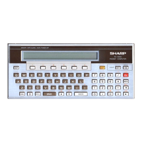
Sharp PC7000A User manual

Sharp

Sharp PC7000A User manual

Sharp YO-250M User manual

Sharp

Sharp YO-250M User manual

Sharp ZQ-4400 User manual

Sharp

Sharp ZQ-4400 User manual

Sharp YO-270 User manual

Sharp

Sharp YO-270 User manual

Sharp PC-AX40 User manual

Sharp

Sharp PC-AX40 User manual

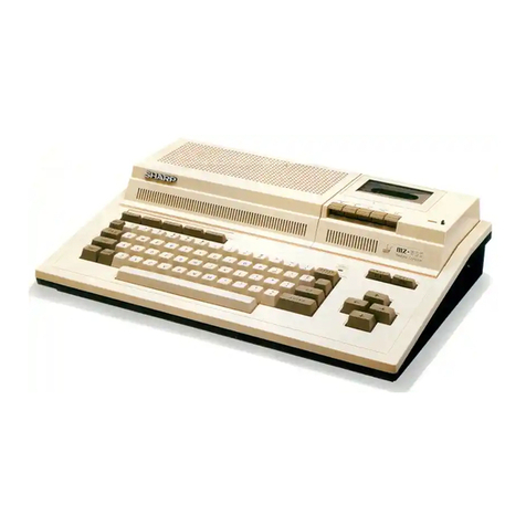
Sharp MZ-3500 Instruction manual

Sharp

Sharp MZ-3500 Instruction manual

Sharp MZ-700 Series Installation guide

Sharp

Sharp MZ-700 Series Installation guide

Sharp MZ-5500 User manual

Sharp

Sharp MZ-5500 User manual

Sharp ZQ-4450M User manual

Sharp

Sharp ZQ-4450M User manual

Sharp PC-7200 User manual

Sharp

Sharp PC-7200 User manual

Sharp MZ-350C User manual

Sharp

Sharp MZ-350C User manual

Sharp PN-L602B User manual

Sharp

Sharp PN-L602B User manual

Sharp PN-TPC1W User manual

Sharp

Sharp PN-TPC1W User manual

Sharp SCR3042FB User manual

Sharp

Sharp SCR3042FB User manual

Sharp Shuttle PN-SPCi5W7 User manual

Sharp

Sharp Shuttle PN-SPCi5W7 User manual

Sharp MZ-3500 User manual

Sharp

Sharp MZ-3500 User manual

Sharp MZ-80A User manual

Sharp

Sharp MZ-80A User manual

Sharp ZQ-3000 User manual

Sharp

Sharp ZQ-3000 User manual

Sharp MZ-80B User manual

Sharp

Sharp MZ-80B User manual

Sharp MZ-80B User manual

Sharp

Sharp MZ-80B User manual

Sharp MZ-800 User manual

Sharp

Sharp MZ-800 User manual

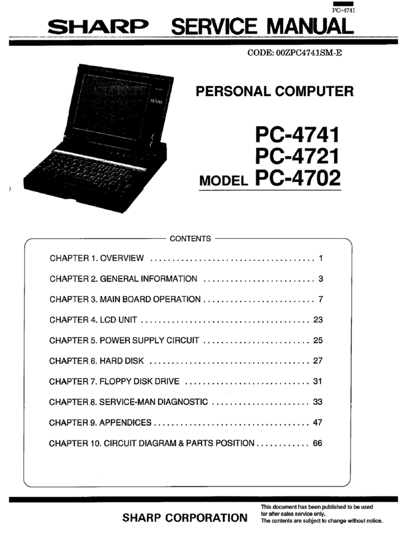
Sharp PC-4741 User manual

Sharp

Sharp PC-4741 User manual

Sharp PC-1500A User manual

Sharp

Sharp PC-1500A User manual

Sharp MZ-800 Use and care manual

Sharp

Sharp MZ-800 Use and care manual

Popular Desktop manuals by other brands

Commodore 16 owner's guide

Commodore

Commodore 16 owner's guide

HP Pavilion 525 Support guide

HP

HP Pavilion 525 Support guide

Compaq BL10e - HP ProLiant - 512 MB RAM introduction

Compaq

Compaq BL10e - HP ProLiant - 512 MB RAM introduction

HP Media Center m7200 - Desktop PC Software guide

HP

HP Media Center m7200 - Desktop PC Software guide

Avalue Technology EPC-WHL Quick reference guide

Avalue Technology

Avalue Technology EPC-WHL Quick reference guide

Compaq AlphaStation XP1000 specification

Compaq

Compaq AlphaStation XP1000 specification

HP Compaq dx6100 MT reference guide

HP

HP Compaq dx6100 MT reference guide

Lenovo ThinkCentre M62z Vodič za korisnike računala

Lenovo

Lenovo ThinkCentre M62z Vodič za korisnike računala

Compaq dc5850 - Microtower PC Illustrated parts & service map

Compaq

Compaq dc5850 - Microtower PC Illustrated parts & service map

HP TouchSmart 310-1000 - Desktop PC quick start guide

HP

HP TouchSmart 310-1000 - Desktop PC quick start guide

Dell Vostro 220s DCSCSF Setup and quick reference guide

Dell

Dell Vostro 220s DCSCSF Setup and quick reference guide

HP Compaq 6000 Pro SFF Quickspecs

HP

HP Compaq 6000 Pro SFF Quickspecs

Gateway E1400 System manual

Gateway

Gateway E1400 System manual

Production Basics 1000-1711 Assembly manual

Production Basics

Production Basics 1000-1711 Assembly manual

Five9NS T3105K1 installation manual

Five9NS

Five9NS T3105K1 installation manual

POLAK ERGO 400 operating instructions

POLAK

POLAK ERGO 400 operating instructions

Lenovo 3000 K100 Hardware Maintenance Manual

Lenovo

Lenovo 3000 K100 Hardware Maintenance Manual

Dell Inspiron 3050 Service manual

Dell

Dell Inspiron 3050 Service manual

manuals.online logo
manuals.online logoBrands
  • About & Mission
  • Contact us
  • Privacy Policy
  • Terms and Conditions

Copyright 2025 Manuals.Online. All Rights Reserved.