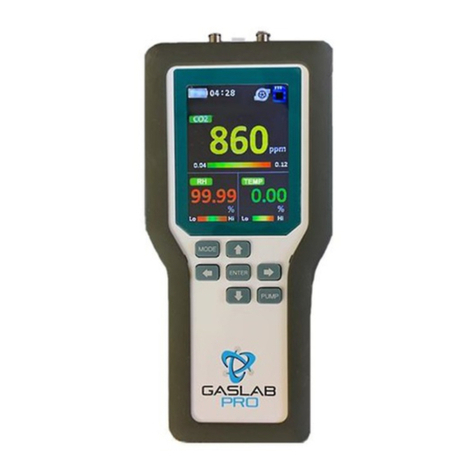
GasLab CM-1000 User manual

GasLab Pro Multi Gas Sampling Data Logger
Operating Instructions
CM-1000
Product Overview
Thank you for selecting the CM-1000 multi gas sampling data logger. The CM-1000is designed to
simultaneously measure multiple gas concentrations through sampling methods.With long-termdata storage,
the user can assess the previous records.When the CM-1000measures the gas concentration reaching the
alarm setting or higher, the data display and alarm functions areactivated. The CM-1000is equipped with
an RS485 interface for connecting to a computer for remote monitoring. The Multi Gas Sampling Data
Logger can be used in a wide-range of industries and applications.
Features:
V□Options for CO2measurement range: 1%, 5%, 10%, 20% 30%, and 100%
V□Measure CO2,CO, O2, CH4, RH, AMB, DP, ALTI
V□Large LCD for easy reading of gas concentration and temperature and humidity.
V□Audible alarm
V□Data logging with SD card
V□Through the RS485 interface connection, multiple CM-1000 units can be connected to the back-end
computer system as a security monitoring application.
V□Built-in LCD back light for easy reading in the dark.
V□This device is supplied with Li- ion 18650 3.7V rechargeable batteries,can be used for along time.
A. Power Key B. Temperature & Humidity Sensor C. LCD
D.Rubber Boot E.Up Key F.Left Key G.Right Key
H.Down Key I. Mode Key J.EnterKey K.Pump Key
L.USB Socket M.SD Card Slot N.RS485 Jack O.Analog / Voltage Output Port
P.Luer Cap
Q.Screw Position
R. Battery Cover
Key description:
MODE (○
I
)
Enterthe setting menu.
Up (○
E
) / Down (○
H
) / Left (○
F
) / Right (○
G
)
Change parameter values or select options.
Enter (○
J
)
Execute a command
PUMP (○
K
)
Start the pump or data logger.
LCD display symbol description:
Symbol
Meaning
Description
CO2concentration,
parts per
million (ppm)The current CO2concentration
CO concentration, partsper
million (ppm)
The current CO concentration
O2concentration,% (percent)
The current O2concentration
CH
4
concentration, parts per
million (ppm)
The current CH4concentration
Relative humidity
Relative humidity
Ambient temperature Ambient temperature
Dew point The current dew point
Atmospheric pressure
Compensate the pressure changes with
appropriate altitude of location when
measure.
Time weighted average (8 hours) CO2, 8-hr time weighted average
Short
‐
TermExposure Limit
(15 min. weightedaverage)
CO2, 15 min. weighted average
Maximum value Maximum value of gas measurement
Minimum value Minimum value of gas measurement
High/low alarm Customize the range of color Bar
Battery capacity Battery capacity without segment display.
Real-time display
12/24-hourtime display
Warning
Need to calibrate the sensor or exceed the
pump life time.
Pump
The pump icon rotates to indicate that the
pump has been started.
Micro SD card
Micro SD card working status (When the
icon flashes, it means that the Micro SD
card is broken or full; when the icon remains
stationary, it indicates normal operation.)
Operation Instructions
1. Power on:
Switch the Power Key (○
A) on.
2. Measurement:
After power on, the device starts to measure and update the data every second.
Press Enterkey (○
J) to select zone. The selection order is: Zone 1Zone 2Zone 3. The selected zone will
display a red frame. Press Left (○
F) / Right (○
G) key to select the parameter or sensor to be adjusted. The
selected parameter orsensor displays the red background color, press Right key (○
G) to proceed the setting
and thenpress Up (○
E) / Down (○
H) key to edit the parameter value.
Zone 1 sensor display: CO2, O2, CO, CH4
Zone 2 sensor display: O2, CO, CH4, RH
Zone 3 sensor display: CO, CH4, AMB, DP,ALTI
Zone 1 parameter display and setting
Item
Select 1
Select 2
Select 3
Select 4
Nothing
MAX
MIN
STEL
TWA
AL L / AL H
Press Up (
○
E
) / Down (
○
H
) key to
edit the parameter value.
–
Note:AL LandAL H are expressed as a percentage. Example: 0.04 = 400ppm
Zone 3 parameter unit selection:
Sensor
Unit 1
Unit 2
Unit 3
Unit 4
DP
DP=°C
DP=°F
–
–
AMB
°C
°F
–
–
ALTI
m
mf
mmHg
hpa
3. Display allsensor readings
Press and hold Enter key (○
J) todisplay all sensorreadings. Press Mode key (○
I) to return to the main
screen.
4. Setting
Press and hold Mode key (○
I) to enter the setup menu, then press Mode key (○
I) to continue to the next
page. Press Up (○
E) / Down(○
H) key to select options or change parameter values.And then press Enter key
(○
J) to confirm it. Press and hold Mode key (○
I) to return to the main screen.
The first page:
Date
01/01/2017 ~ 2099
Time
12/24-hourtime
Continue alarm
Yes (The buzzer sounds continuously.) / No (The buzzer sounds once.)
Screen auto rotate
Yes / No
Backlight level
1~32 (The larger the number, the brighter the screen)
Background color
□□□□
(There are a total of 4 background colors.)
Backlight time
10~999 sec (Backlight display time)
Auto power off
1~999 min
Graph line 2
CO2/ O2/CO/ CH4 (The second trendline shows the gas measurements.)
About
CO2Meter – www.co2meter.com
The second page:
Analog for Zone 1
0-10V/4~20mA (Zone 1 voltage or current output)
Analog for 4-20mA
CO2/O2/CO/CH4 (Another analog output option)
Data log time
Data logging interval time
Flow rate level
1~5 (The largerthe number, the greater the pump output)
Exhaust time
10~240 sec
Ventilate time
0~120 sec
Gas compensation
Yes / No (CO2 and O2)
Sensor times info
Sensor recalibrated time and pump life time (The time is displayed in the
countdown mode. If you need to calibrate the sensor or exceed the pump
life time, the time will be displayed in red.)
CO2: 99999999 days
O2: 99999999 days
CO: 99999999 days
CH4: 99999999 days
Pump: 99999999 min
Reset to factory
Yes / No (Recover the factory setting to cancel customize setting.)
Sensor calibration (▲+▼)
Please refer to the calibration section.
5. Power off:
Switch the Power Key (○
A) off.
Note: When the device is charged with USB, it cannot be turned off.
6. Calibration:
(1) Single-point calibration
After entering the setup menu, then press Mode key (○
I)to continueto thenextpage. Press Down key (○
H) to
select"Sensor calibration (▲+▼)"and press Enter key (○
J)to confirmit. Press Up(○
E)and Down (○
H)keys
at the same time to proceed the calibration. Then, press Enter key (○
J) to enter the sensor settings.
Target sensor
CO2/O2/CO/CH4/AMB/RH
Raw reading
Unadjusted reading
Offset
The amount of offset
Perform reading
Adjusted reading
(2) Two-point calibration (calibrate by professional)
After entering the setup menu, then press Mode key (○
I) to continue to the next page. Firstly, press and hold
Up key (○
E), then press Down key (○
H). ”1” will appear next to "Sensor calibration (▲+▼)". Press Down
key (○
H) to select "Sensor calibration (▲+▼) 1" and press Enter key (○J) to confirm it. Press Up (○
E) and
Down (○
H) keys at the same time to proceed the calibration. Then, press Enter key (○J) to enter the sensor
settings.
Target sensor
CO2/O2/CO/CH4/AMB/RH
Raw reading
Unadjusted reading
Level 1 input
Low concentration value of standard gas
Level 2 input
High concentration value of standard gas
Level 1 catch
Connect the low concentration gas to the device, and
press Pump key (○K) to start the pump. (Set the data
log time to less than 1 min). After the reading is
stable, press Enter key (
○J
) to confirm it.
Level 2 catch Connect the high concentration gas to the device,
and press Pump key (○
K) to start the pump. (Set the
data log time to less than 1 min). After the reading is
stable, press Enter key (
○J
) to confirm it.
Cali Set
When "Start" turns red, press Enterkey (
○J
) to
confirm the calibration.
Gain The amount of Gain.
Offset
The amount of offset
Perform reading Adjusted reading
(Display Features and Modes)

Rechargeable Batteries
Battery message:
‘Battery OK’:
Measurements are possible ‘Battery Low’:
The battery needs to be recharged,
measurements are still possible
‘Battery Exhausted’:
Measurements are not
possible
Battery installation:
This device is supplied with Li-ion 18650 3.7V rechargeable battery *3 pcs.
Please confirm whether batteries + polarity are Li ion18650 positive bump specification and install batteries in
the correct polarity. If the battery polarity is reversed, the capacity will be insufficient and the battery life will be
shortened.
Battery charging:
During battery charging, the temperature of the device will rise by 5°C~10°C. At this time, the measurements
of temperature and humidity will be affected by temperature rise. Cause an impact on the accuracy of
temperature when charging, please use a fan to blow towardthe Temperature& Humidity Sensor (○
B) directly
in order to get a compensated balance of temperature and humidity between temperature sensor and
surrounding area. (5V/1A USB adapter charger)
Safety Instructions
Warning: Your safety is very important to us. To ensure use of the device correctly and safely, we would like to
draw your attention to read the warning and entire User Manual before using the device. These are important
safety information and should always be observed .
1. Please handle the device lightly, do not subject the device to impact or shock.
2. Do not immerse the device in water. Water can cause electric shock, fire or malfunction which may result in
damage.
3. Donot keepthedeviceunder thehot and moisture environment.Keepthedevice awayfromthe heatsource
or near water.
4. Please use a standard USB power supply (such as PC's USB port, universal AC adapter with USB port).
Improper power supply can cause serious damage to the device, or result in injury or death to the user.
Product Care
To ensure you receive the maximum benefit from using this device, please observe the follow guidelines.
1.The maximum capacity of the SD card is 16G.
2.During battery charging, the temperature of the device rises. The temperature and humidity sensors are
affected. At this time, measurements are only for reference. After batteries are fully charged and the device
cools down, measurements are reliable.
3. Repair – Do not attempt to repair the device or modify the circuitry by yourself. Please contact with the local
dealer or a qualified repairman if the device needs servicing.
4. Caution –The CO sensor must be replaced every 3 years.
5.Cleaning – Disconnect the power before clean. Use a damp cloth, do not use the liquid cleaning agent, such
as benzene, thinner or aerosols.
6.Maintenance – Recommend that the user conducts a comprehensive test and calibration every year to
ensure the normal operation of the device.
Specifications
Measurement Range &
Accuracy
CO2:1%,5%, 10%, 20%, 30%, 100%
CO: 0~1,000ppm
O2: 0~25%, < 2% FS / 0.1 mbar
CH4: 5% 0-1%: ≤±0.1%
RH: 0~100%, ±3% @25°C (20~80%RH), others ±5%
Temperature: 0~50°C,±1℃
Barometer: 50~110kPa,
±
0.4kPa
Display Resolution
CO2:10ppm
CO: 1ppm
O2: 0.01%
CH4:0.01%
RH: 0.01%
Temperature: 0.01°C
Barometer: 0.1mmHg
Alarm Volume
80db±5%@10cm
Operating Conditions
0~50°C(32~122°F), 0~95%RH, non-condensing
Storage Temp.
-20~60°C(-4~140°F)
Comm. Interface RS485 ModBus BR19200、N、8、1
Power Supply
Rechargeable Battery : Li-ion 18650 3.7V *3
AC Adapter : 5V±5% >1A, 100~240 VAC, 50/60 Hz
Storage Capacity
depend on SD card capacity (max.16G SD card)
Weight
480g (without batteries)
Dimension
225.8x99.6x55 mm (8.9x3.9x2.2inch)
Note: After power-on, it would take 20 minutes for the device to stably measure the temperature and
relative humidity.
EMC/RFI: Readings may be affected if the unit is operated within radio frequency electromagnetic field
strength of approximately 3 volts per meter, but the performance of the instrument will not be
permanently affected.
Package contents
CM-1000 Multi Gas Sampling Logger
Manual
Batteries
USB 1.5M cable
Ref.No.:122018
Contact Details:
Exclusively Distributed & Supported By:
Air Quality Sensors
Ph: 1300 430 928
www.airqualitysensors.com.au
Other GasLab Data Logger manuals
Popular Data Logger manuals by other brands
Smacq Technologies Co., Ltd.
Smacq Technologies Co., Ltd. PS2016 Series user manual

DATAGRABBER
DATAGRABBER Rapid RH L6 instruction manual
ASTRO-MED
ASTRO-MED Dash 8X quick start guide
EIJKELKAMP
EIJKELKAMP PlantControl D operating instructions
PowerFleet
PowerFleet LV9000 user manual
Racelogic
Racelogic VBOX II manual
TECHNOLOG
TECHNOLOG Cello 4S product manual
HMW
HMW LoLog 450 Series Basic user manual
Onset
Onset HOBO Pendant UA-001 Series manual
Hydro International
Hydro International Hydro-Logic Flexi Logger 105 user manual

Keynes Controls
Keynes Controls NDACS 6000 Quick user guide
Gemini
Gemini Tinyview TV-0020 manual

